User Manual
Page 1
R P/I-P55T2P4 Pentium® Motherboard USER'S MANUAL
R P/I-P55T2P4 Pentium® Motherboard USER'S MANUAL

User Manual
Page 2
... without notice. Product Name: P/I-P55T2P4 Product Rev: 2.1 Manual Rev: 2.0 BIOS Version: #401A0-0101 (Displayed on top left during boot-up) Release Date: April 1996 II P/I-P55T2P4 User's Manual ASUS may revise this manual from any defect or error in this manual may or may not be reproduced,... transmitted, transcribed, stored in a retrieval system, or translated into any language in this manual are mentioned for a particular purpose...
... without notice. Product Name: P/I-P55T2P4 Product Rev: 2.1 Manual Rev: 2.0 BIOS Version: #401A0-0101 (Displayed on top left during boot-up) Release Date: April 1996 II P/I-P55T2P4 User's Manual ASUS may revise this manual from any defect or error in this manual may or may not be reproduced,... transmitted, transcribed, stored in a retrieval system, or translated into any language in this manual are mentioned for a particular purpose...
User Manual
Page 4
...Memory Installation Procedures 13 Level 2 External Static RAM (SRAM) Cache 14 Compatible Cache Modules for ISA Cards 17 ASUS MediaBus Card 18 5. Central Processing Unit (CPU 15 4. Expansion Cards 16 Expansion Card Installation Procedure 16 Assigning IRQs... for Expansion Cards 16 Assigning DMA Channels for this manual is organized 1 Item Checklist 1 II. External Connectors 19 Final Power Connection Procedures 25 IV P/I . CONTENTS I -P55T2P4 User's Manual Jumpers 6 Jumper Settings 8 2. INSTALLATION 4 Map of the Motherboard 3 III...
...Memory Installation Procedures 13 Level 2 External Static RAM (SRAM) Cache 14 Compatible Cache Modules for ISA Cards 17 ASUS MediaBus Card 18 5. Central Processing Unit (CPU 15 4. Expansion Cards 16 Expansion Card Installation Procedure 16 Assigning IRQs... for Expansion Cards 16 Assigning DMA Channels for this manual is organized 1 Item Checklist 1 II. External Connectors 19 Final Power Connection Procedures 25 IV P/I . CONTENTS I -P55T2P4 User's Manual Jumpers 6 Jumper Settings 8 2. INSTALLATION 4 Map of the Motherboard 3 III...
User Manual
Page 5
... The PCI-SC200 SCSI Interface Card 52 Setting Up the PCI-SC200 52 Setting the INT Assignment 53 Terminator Settings 53 SCSI ID Numbers 54 P/I-P55T2P4 User's Manual V CONTENTS IV. BIOS SOFTWARE 26 6.
... The PCI-SC200 SCSI Interface Card 52 Setting Up the PCI-SC200 52 Setting the INT Assignment 53 Terminator Settings 53 SCSI ID Numbers 54 P/I-P55T2P4 User's Manual V CONTENTS IV. BIOS SOFTWARE 26 6.
User Manual
Page 6
... card is encouraged to try to correct the interference by the party responsible for radio noise emissions from that to Part 15 of Communications. VI P/I-P55T2P4 User's Manual This equipment has been tested and found to comply with the limits for a Class B digital device, pursuant to which can radiate radio frequency energy...
... card is encouraged to try to correct the interference by the party responsible for radio noise emissions from that to Part 15 of Communications. VI P/I-P55T2P4 User's Manual This equipment has been tested and found to comply with the limits for a Class B digital device, pursuant to which can radiate radio frequency energy...
User Manual
Page 7
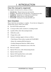
...Readme files gives instructions on setting up the motherboard. 4. I.INTRODUCTION (Manual/Checklist) I -P55T2P4 User's Manual 1 INTRODUCTION How this product 3. BIOS Setup: BIOS software setup information. 5. Introduction: Manual information and checklist 2. If you discover damaged or missing items, please...infrared module Optional ASUS pipelined burst cache module Optional PCI-SC200 SCSI card P/I . Features: Information and specifications concerning this manual is organized This manual is complete. PCI-SC200: Installation of the files √ This user's manual Optional PS/2 ...
...Readme files gives instructions on setting up the motherboard. 4. I.INTRODUCTION (Manual/Checklist) I -P55T2P4 User's Manual 1 INTRODUCTION How this product 3. BIOS Setup: BIOS software setup information. 5. Introduction: Manual information and checklist 2. If you discover damaged or missing items, please...infrared module Optional ASUS pipelined burst cache module Optional PCI-SC200 SCSI card P/I . Features: Information and specifications concerning this manual is organized This manual is complete. PCI-SC200: Installation of the files √ This user's manual Optional PS/2 ...
User Manual
Page 8
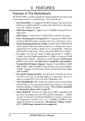
... multifunctional expansion card which allows hardware to communicate within a standard protocol creating a higher level of either an standard PCI card or the ASUS MediaBus Card. • ASUS MediaBus Rev 2.0: Features an expansion slot extension shared with BIOS supports auto detection of hard drives and Plug and Play to make setup... DMI which facilitates building of 4MB, 8MB, 16MB, 32MB, or 64MB to form a memory size between 8MB to page 18.) • Super Multi-I -P55T2P4 User's Manual FEATURES (Features) II. Two floppy drives of compatibility. (Requires DMI-enabled components.
... multifunctional expansion card which allows hardware to communicate within a standard protocol creating a higher level of either an standard PCI card or the ASUS MediaBus Card. • ASUS MediaBus Rev 2.0: Features an expansion slot extension shared with BIOS supports auto detection of hard drives and Plug and Play to make setup... DMI which facilitates building of 4MB, 8MB, 16MB, 32MB, or 64MB to form a memory size between 8MB to page 18.) • Super Multi-I -P55T2P4 User's Manual FEATURES (Features) II. Two floppy drives of compatibility. (Requires DMI-enabled components.
User Manual
Page 9
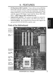
...8226; PCI Bus Master IDE Controller: Comes with an on-board PCI Bus Master IDE controller with two connectors that supports the optional ASUS PCI-SC200 SCSI controller cards. BIOS supports IDE CD-ROM boot-up. • Optional IrDA and PS/2: This motherboard supports an ... 3 ISA Slots Flash ROM 3 PCI Slots Super Multi-I/O PCI 4 or ASUS MediaBus 2.0 72-pin SIMM Sockets Intel's 430HX PCIset CPU ZIF Socket 7 L2 Upgrade Cache Expansion Slot On-Board 256KB/ 512KB Pipelined Burst L2 Cache P/I-P55T2P4 User's Manual 3 FEATURES (PartsofBoard) II. This controller supports PIO Modes 3 and 4 ...
...8226; PCI Bus Master IDE Controller: Comes with an on-board PCI Bus Master IDE controller with two connectors that supports the optional ASUS PCI-SC200 SCSI controller cards. BIOS supports IDE CD-ROM boot-up. • Optional IrDA and PS/2: This motherboard supports an ... 3 ISA Slots Flash ROM 3 PCI Slots Super Multi-I/O PCI 4 or ASUS MediaBus 2.0 72-pin SIMM Sockets Intel's 430HX PCIset CPU ZIF Socket 7 L2 Upgrade Cache Expansion Slot On-Board 256KB/ 512KB Pipelined Burst L2 Cache P/I-P55T2P4 User's Manual 3 FEATURES (PartsofBoard) II. This controller supports PIO Modes 3 and 4 ...
User Manual
Page 10
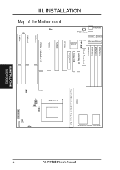
INSTALLATION FOR SMC 37C669 SIMM Slot 4 SIMM Slot 3 SIMM Slot 2 SIMM Slot 1 Board Power Input JP1 Secondary IDE MULTI I/O UMC OR SMC Primary IDE PCI Slot 1 Floppy Drives PCI Slot 2 PCI Slot 3 PCI Slot 4 / MediaBus 2.0 ISA Slot 1 ISA Slot 2 ISA Slot 3 JP19 JP13 Fan Power Pipelined Burst Level 2 Cache Expansion Slot ZIF Socket 7 JP11 JP12 JP9 JP10 JP20 I -P55T2P4 User's Manual Map of Board) INSTALLATION (Map of the Motherboard JP8 JP18 III. JP2 256KB On-Board L2 Cache Parallel Printer COM 1 COM 2 Keyboard PS/2 Mouse P/I R IDE LED JP17 CON1 4 III.
INSTALLATION FOR SMC 37C669 SIMM Slot 4 SIMM Slot 3 SIMM Slot 2 SIMM Slot 1 Board Power Input JP1 Secondary IDE MULTI I/O UMC OR SMC Primary IDE PCI Slot 1 Floppy Drives PCI Slot 2 PCI Slot 3 PCI Slot 4 / MediaBus 2.0 ISA Slot 1 ISA Slot 2 ISA Slot 3 JP19 JP13 Fan Power Pipelined Burst Level 2 Cache Expansion Slot ZIF Socket 7 JP11 JP12 JP9 JP10 JP20 I -P55T2P4 User's Manual Map of Board) INSTALLATION (Map of the Motherboard JP8 JP18 III. JP2 256KB On-Board L2 Cache Parallel Printer COM 1 COM 2 Keyboard PS/2 Mouse P/I R IDE LED JP17 CON1 4 III.
User Manual
Page 11
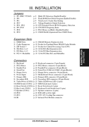
... Speaker connector (4-pins) 14) JP20 p. 24 IDE LED activity light 15) JP13 p. 24 CPU 12V Cooling Fan connector 16) IR p. 25 Infrared Port Module connector P/I-P55T2P4 User's Manual 5 III.
... Speaker connector (4-pins) 14) JP20 p. 24 IDE LED activity light 15) JP13 p. 24 CPU 12V Cooling Fan connector 16) IR p. 25 Infrared Port Module connector P/I-P55T2P4 User's Manual 5 III.
User Manual
Page 12
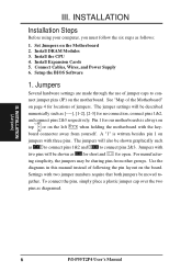
...Jumpers on page 4 for open. See "Map of following the pin layout on the motherboard. Use the diagrams in this manual instead of the Motherboard" on the Motherboard 2. nect jumper pins (JP) on the board. A "1" is always on Pin... settings will be sharing pins from yourself. Install Expansion Cards 5. Jumpers with two pins will also be moved to- INSTALLATION (Jumpers) 6 P/I-P55T2P4 User's Manual Pin 1 for no connection, connect pins 1&2, and connect pins 2&3 respectively. The jumpers will be shown as [----], [1-2], [2-3] for our motherboards...
...Jumpers on page 4 for open. See "Map of following the pin layout on the motherboard. Use the diagrams in this manual instead of the Motherboard" on the Motherboard 2. nect jumper pins (JP) on the board. A "1" is always on Pin... settings will be sharing pins from yourself. Install Expansion Cards 5. Jumpers with two pins will also be moved to- INSTALLATION (Jumpers) 6 P/I-P55T2P4 User's Manual Pin 1 for no connection, connect pins 1&2, and connect pins 2&3 respectively. The jumpers will be shown as [----], [1-2], [2-3] for our motherboards...
User Manual
Page 13
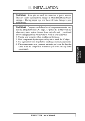
... contain very delicate Integrated Circuit (IC) chips. Hold components by the edges and try not to your computer when working on page 4. III. INSTALLATION (Jumpers) P/I-P55T2P4 User's Manual 7 INSTALLATION WARNING: Some pins are clearly separated from static electricity, you should follow some precautions whenever you work on lay down components. III.
... contain very delicate Integrated Circuit (IC) chips. Hold components by the edges and try not to your computer when working on page 4. III. INSTALLATION (Jumpers) P/I-P55T2P4 User's Manual 7 INSTALLATION WARNING: Some pins are clearly separated from static electricity, you should follow some precautions whenever you work on lay down components. III.
User Manual
Page 14
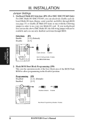
.... On-Board Multi-I/O Selection (JP1) (For SMC SMC37C669 Only) For SMC Multi-I /O card. Selections Enable Disable JP1 [1-2] (Default) [2-3] JP 1 1 2 3 Enable (Default) JP 1 1 2 3 Disabled Multi I -P55T2P4 User's Manual INSTALLATION Jumper Settings 1. Programming JP8 Disabled [1-2] (Default) Enabled [2-3] JP8 123 Disabled (Default) JP8 123 Enabled Boot Block Programming (Disable / Enable) 8 P/I /O Setting (Enable / Disable) (For SMC...
.... On-Board Multi-I/O Selection (JP1) (For SMC SMC37C669 Only) For SMC Multi-I /O card. Selections Enable Disable JP1 [1-2] (Default) [2-3] JP 1 1 2 3 Enable (Default) JP 1 1 2 3 Disabled Multi I -P55T2P4 User's Manual INSTALLATION Jumper Settings 1. Programming JP8 Disabled [1-2] (Default) Enabled [2-3] JP8 123 Disabled (Default) JP8 123 Enabled Boot Block Programming (Disable / Enable) 8 P/I /O Setting (Enable / Disable) (For SMC...
User Manual
Page 15
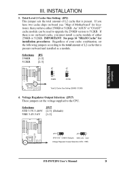
An "ASUS" or "COAST" cache module can be used to upgrade the 256KB version to the CPU. Voltage Regulator Output Selection (JP17) These jumpers set the following ... Cache Size Setting (256KB / 512KB) 4. INSTALLATION (Jumpers) JP17 123 STD 3.3V - 3.465V (Default) JP17 123 VRE 3.4V - 3.6V Voltage Regulator Output Selection (STD / VRE) P/I-P55T2P4 User's Manual 9 If there is present on -board cache, you have either 256KB or 512KB. Total Level 2 Cache Size Setting (JP2) This jumper sets the total amount...
An "ASUS" or "COAST" cache module can be used to upgrade the 256KB version to the CPU. Voltage Regulator Output Selection (JP17) These jumpers set the following ... Cache Size Setting (256KB / 512KB) 4. INSTALLATION (Jumpers) JP17 123 STD 3.3V - 3.465V (Default) JP17 123 VRE 3.4V - 3.6V Voltage Regulator Output Selection (STD / VRE) P/I-P55T2P4 User's Manual 9 If there is present on -board cache, you have either 256KB or 512KB. Total Level 2 Cache Size Setting (JP2) This jumper sets the total amount...
User Manual
Page 16
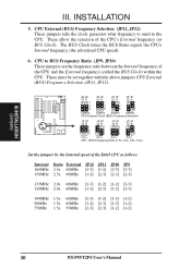
... JP10 JP9 166MHz 2.5x 66MHz [2-3] [1-2] [2-3] [2-3] 150MHz 2.5x 60MHz [1-2] [2-3] [2-3] [2-3] 133MHz 2.0x 66MHz [2-3] [1-2] [1-2] [2-3] 120MHz 2.0x 60MHz [1-2] [2-3] [1-2] [2-3] 100MHz 1.5x 66MHz 90MHz 1.5x 60MHz 75MHz 1.5x 50MHz [2-3] [1-2] [1-2] [1-2] [1-2] [2-3] [1-2] [1-2] [2-3] [2-3] [1-2] [1-2] 10 P/I-P55T2P4 User's Manual INSTALLATION 5. The BUS Clock times the BUS Ratio equals the CPU's Internal frequency (the advertised CPU speed). 6. CPU External (BUS) Frequency Selection (JP11, JP12) These...
... JP10 JP9 166MHz 2.5x 66MHz [2-3] [1-2] [2-3] [2-3] 150MHz 2.5x 60MHz [1-2] [2-3] [2-3] [2-3] 133MHz 2.0x 66MHz [2-3] [1-2] [1-2] [2-3] 120MHz 2.0x 60MHz [1-2] [2-3] [1-2] [2-3] 100MHz 1.5x 66MHz 90MHz 1.5x 60MHz 75MHz 1.5x 50MHz [2-3] [1-2] [1-2] [1-2] [1-2] [2-3] [1-2] [1-2] [2-3] [2-3] [1-2] [1-2] 10 P/I-P55T2P4 User's Manual INSTALLATION 5. The BUS Clock times the BUS Ratio equals the CPU's Internal frequency (the advertised CPU speed). 6. CPU External (BUS) Frequency Selection (JP11, JP12) These...
User Manual
Page 17
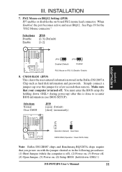
... the jumper shorted as in the Dallas DS12887A Chip such as hard disk information and passwords. You must enter the BIOS setup (by holding down ) P/I-P55T2P4 User's Manual 11
... the jumper shorted as in the Dallas DS12887A Chip such as hard disk information and passwords. You must enter the BIOS setup (by holding down ) P/I-P55T2P4 User's Manual 11
User Manual
Page 18
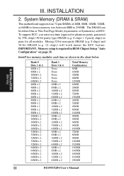
... 24MB 40MB 72MB 136MB 24MB 32MB 48MB 80MB 144MB 40MB 48MB 64MB 96MB 160MB 72MB 80MB 96MB 128MB 192MB 136MB 144MB 160MB 192MB 256MB 12 P/I-P55T2P4 User's Manual Install two memory modules each time as shown in BIOS Chipset Setup "Auto Configuration" on page 35. IMPORTANT: Memory setup is required in the...
... 24MB 40MB 72MB 136MB 24MB 32MB 48MB 80MB 144MB 40MB 48MB 64MB 96MB 160MB 72MB 80MB 96MB 128MB 192MB 136MB 144MB 160MB 192MB 256MB 12 P/I-P55T2P4 User's Manual Install two memory modules each time as shown in BIOS Chipset Setup "Auto Configuration" on page 35. IMPORTANT: Memory setup is required in the...

User Manual
Page 19
DRAM Memory Installation Procedures: 1. P/I-P55T2P4 User's Manual 13 INSTALLATION IMPORTANT: Do not use an extra TTL chip to symmetric. Modules with more than 24 chips per module. Press the memory module firmly ...
DRAM Memory Installation Procedures: 1. P/I-P55T2P4 User's Manual 13 INSTALLATION IMPORTANT: Do not use an extra TTL chip to symmetric. Modules with more than 24 chips per module. Press the memory module firmly ...
User Manual
Page 20
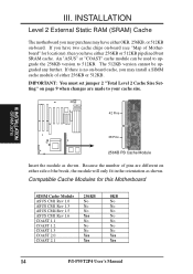
... shown. III. IMPORTANT: You must set jumper 2 "Total Level 2 Cache Size Setting" on either 256KB or 512KB. An "ASUS" or "COAST" cache module can be upgraded any further. III. Because the number of Motherboard" for this Motherboard SIMM Cache Module 256KB 0KB... ASUS CM1 Rev 1.0 No No ASUS CM1 Rev 1.3 No No ASUS CM4 Rev 1.5 No No ASUS CM1 Rev 1.6 Yes No COAST 1.1 No No COAST 1.2 No No COAST 1.3 No No COAST 2.0 Yes Yes COAST 2.1 Yes Yes 14 P/I-P55T2P4 User's Manual INSTALLATION Level 2 External Static RAM ...
... shown. III. IMPORTANT: You must set jumper 2 "Total Level 2 Cache Size Setting" on either 256KB or 512KB. An "ASUS" or "COAST" cache module can be upgraded any further. III. Because the number of Motherboard" for this Motherboard SIMM Cache Module 256KB 0KB... ASUS CM1 Rev 1.0 No No ASUS CM1 Rev 1.3 No No ASUS CM4 Rev 1.5 No No ASUS CM1 Rev 1.6 Yes No COAST 1.1 No No COAST 1.2 No No COAST 1.3 No No COAST 2.0 Yes Yes COAST 2.1 Yes Yes 14 P/I-P55T2P4 User's Manual INSTALLATION Level 2 External Static RAM ...
User Manual
Page 21
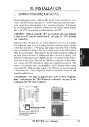
... on the motherboard next to the CPU top and then install the fan onto the CPU. Lever Lock Blank Pentium Processor & ZIF Socket 7 White Dot P/I-P55T2P4 User's Manual 15 INSTALLATION (CPU) III. Apply thermal jelly to that is not the case then purchase a fan before you install. III.
... on the motherboard next to the CPU top and then install the fan onto the CPU. Lever Lock Blank Pentium Processor & ZIF Socket 7 White Dot P/I-P55T2P4 User's Manual 15 INSTALLATION (CPU) III. Apply thermal jelly to that is not the case then purchase a fan before you install. III.


