
User Manual
Page 1
R P/I-P55T2P4 Pentium® Motherboard USER'S MANUAL
R P/I-P55T2P4 Pentium® Motherboard USER'S MANUAL
User Manual
Page 4
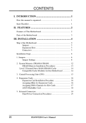
CONTENTS I -P55T2P4 User's Manual System Memory (DRAM & SRAM 12 DRAM Memory Installation Procedures 13 Level 2 External Static RAM (SRAM) Cache 14 Compatible Cache Modules for ISA Cards 17 ASUS MediaBus Card 18 5. External Connectors 19 Final Power Connection Procedures 25 IV P/I . INTRODUCTION 1 How this Motherboard 14 3. FEATURES 2 Features of This Motherboard 2 Parts of the Motherboard 4 Jumpers...
CONTENTS I -P55T2P4 User's Manual System Memory (DRAM & SRAM 12 DRAM Memory Installation Procedures 13 Level 2 External Static RAM (SRAM) Cache 14 Compatible Cache Modules for ISA Cards 17 ASUS MediaBus Card 18 5. External Connectors 19 Final Power Connection Procedures 25 IV P/I . INTRODUCTION 1 How this Motherboard 14 3. FEATURES 2 Features of This Motherboard 2 Parts of the Motherboard 4 Jumpers...
User Manual
Page 7
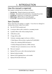
...Information and specifications concerning this manual is organized This manual is complete. Item Checklist Please check that your retailer. √ The P/I-P55T2P4 motherboard √ 2 serial port ribbon cables attached to update the FLASH BIOS • Binary file containing BIOS information • Desktop... Writer utility to a mounting bracket √ 1 parallel ribbon cable with mounting bracket Optional infrared module Optional ASUS pipelined burst cache module Optional PCI-SC200 SCSI card P/I . BIOS Setup: BIOS software setup information. 5. I.INTRODUCTION (Manual/Checklist...
...Information and specifications concerning this manual is organized This manual is complete. Item Checklist Please check that your retailer. √ The P/I-P55T2P4 motherboard √ 2 serial port ribbon cables attached to update the FLASH BIOS • Binary file containing BIOS information • Desktop... Writer utility to a mounting bracket √ 1 parallel ribbon cable with mounting bracket Optional infrared module Optional ASUS pipelined burst cache module Optional PCI-SC200 SCSI card P/I . BIOS Setup: BIOS software setup information. 5. I.INTRODUCTION (Manual/Checklist...
User Manual
Page 8
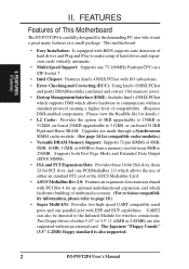
... cache module. (See page 14 for wireless connections. Two floppy drives of either an standard PCI card or the ASUS MediaBus Card. • ASUS MediaBus Rev 2.0: Features an expansion slot extension shared with PCI Slot 4 for the demanding PC user who wants ... an optional multifunctional expansion card which allows hardware to communicate within a standard protocol creating a higher level of This Motherboard The P/I -P55T2P4 User's Manual This motherboard: • Easy Installation: Is equipped with BIOS supports auto detection of multimedia systems. (For revision compatibility information...
... cache module. (See page 14 for wireless connections. Two floppy drives of either an standard PCI card or the ASUS MediaBus Card. • ASUS MediaBus Rev 2.0: Features an expansion slot extension shared with PCI Slot 4 for the demanding PC user who wants ... an optional multifunctional expansion card which allows hardware to communicate within a standard protocol creating a higher level of This Motherboard The P/I -P55T2P4 User's Manual This motherboard: • Easy Installation: Is equipped with BIOS supports auto detection of multimedia systems. (For revision compatibility information...
User Manual
Page 9
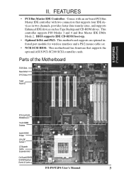
...data transfer rates, and supports Enhanced IDE devices such as Tape Backup and CD-ROM drives. Parts of the Motherboard 3 ISA Slots Flash ROM 3 PCI Slots Super Multi-I/O PCI 4 or ASUS MediaBus 2.0 72-pin SIMM Sockets Intel's 430HX PCIset CPU ZIF Socket 7 L2 Upgrade Cache Expansion Slot On-...Board 256KB/ 512KB Pipelined Burst L2 Cache P/I-P55T2P4 User's Manual 3 II. FEATURES • PCI Bus Master IDE Controller: Comes with...
...data transfer rates, and supports Enhanced IDE devices such as Tape Backup and CD-ROM drives. Parts of the Motherboard 3 ISA Slots Flash ROM 3 PCI Slots Super Multi-I/O PCI 4 or ASUS MediaBus 2.0 72-pin SIMM Sockets Intel's 430HX PCIset CPU ZIF Socket 7 L2 Upgrade Cache Expansion Slot On-...Board 256KB/ 512KB Pipelined Burst L2 Cache P/I-P55T2P4 User's Manual 3 II. FEATURES • PCI Bus Master IDE Controller: Comes with...
User Manual
Page 10
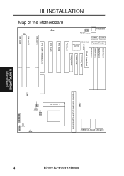
JP2 256KB On-Board L2 Cache Parallel Printer COM 1 COM 2 Keyboard PS/2 Mouse P/I R IDE LED JP17 CON1 4 III. INSTALLATION (Map of the Motherboard JP8 JP18 III. INSTALLATION FOR SMC 37C669 SIMM Slot 4 SIMM Slot 3 SIMM Slot 2 SIMM Slot 1 Board Power Input JP1 Secondary IDE MULTI I/O UMC OR SMC Primary IDE PCI Slot 1 Floppy Drives PCI Slot 2 PCI Slot 3 PCI Slot 4 / MediaBus 2.0 ISA Slot 1 ISA Slot 2 ISA Slot 3 JP19 JP13 Fan Power Pipelined Burst Level 2 Cache Expansion Slot ZIF Socket 7 JP11 JP12 JP9 JP10 JP20 I -P55T2P4 User's Manual Map of Board)
JP2 256KB On-Board L2 Cache Parallel Printer COM 1 COM 2 Keyboard PS/2 Mouse P/I R IDE LED JP17 CON1 4 III. INSTALLATION (Map of the Motherboard JP8 JP18 III. INSTALLATION FOR SMC 37C669 SIMM Slot 4 SIMM Slot 3 SIMM Slot 2 SIMM Slot 1 Board Power Input JP1 Secondary IDE MULTI I/O UMC OR SMC Primary IDE PCI Slot 1 Floppy Drives PCI Slot 2 PCI Slot 3 PCI Slot 4 / MediaBus 2.0 ISA Slot 1 ISA Slot 2 ISA Slot 3 JP19 JP13 Fan Power Pipelined Burst Level 2 Cache Expansion Slot ZIF Socket 7 JP11 JP12 JP9 JP10 JP20 I -P55T2P4 User's Manual Map of Board)
User Manual
Page 11
... (26-pin Block) 4) Serial Port p. 20 Serial Port COM1 & COM2 (10-pin Blocks) 5) Floppy Drive p. 21 Floppy Drive connector (34-pin Block) 6) Power Input p. 21 Motherboard Power connector (12-pin Block) 7) Primary IDE p. 22 Primary IDE connector (40-pin Block) 8) Secondary IDE p. 22 Secondary IDE connector (40-pin Block) 9) Turbo/Power... Speaker connector (4-pins) 14) JP20 p. 24 IDE LED activity light 15) JP13 p. 24 CPU 12V Cooling Fan connector 16) IR p. 25 Infrared Port Module connector P/I-P55T2P4 User's Manual 5
... (26-pin Block) 4) Serial Port p. 20 Serial Port COM1 & COM2 (10-pin Blocks) 5) Floppy Drive p. 21 Floppy Drive connector (34-pin Block) 6) Power Input p. 21 Motherboard Power connector (12-pin Block) 7) Primary IDE p. 22 Primary IDE connector (40-pin Block) 8) Secondary IDE p. 22 Secondary IDE connector (40-pin Block) 9) Turbo/Power... Speaker connector (4-pins) 14) JP20 p. 24 IDE LED activity light 15) JP13 p. 24 CPU 12V Cooling Fan connector 16) IR p. 25 Infrared Port Module connector P/I-P55T2P4 User's Manual 5
User Manual
Page 12
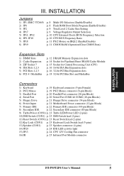
... 1 for locations of following the pin layout on page 4 for our motherboards is written besides pin 1 on the Motherboard 2. Use the diagrams in this manual instead of jumpers. INSTALLATION (Jumpers) 6 P/I-P55T2P4 User's Manual See "Map of jumper caps to connect pins 2&3. board ...connector away from other groups. A "1" is always on Pin 1 Pin 1 top or on the motherboard. gether. III. The jumper settings will be described ...
... 1 for locations of following the pin layout on page 4 for our motherboards is written besides pin 1 on the Motherboard 2. Use the diagrams in this manual instead of jumpers. INSTALLATION (Jumpers) 6 P/I-P55T2P4 User's Manual See "Map of jumper caps to connect pins 2&3. board ...connector away from other groups. A "1" is always on Pin 1 Pin 1 top or on the motherboard. gether. III. The jumper settings will be described ...
User Manual
Page 13
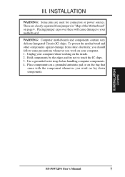
...IC) chips. Hold components by the edges and try not to your computer when working on page 4. Unplug your motherboard. These are used for connectors or power sources. Placing jumper caps over these will cause damage to touch the IC chips. 3.... INSTALLATION (Jumpers) P/I-P55T2P4 User's Manual 7 Use a grounded wrist strap before handling computer components. 4. To protect the motherboard and other components against damage from jumpers in "Map of the Motherboard" on the inside. 2. Place components on a grounded antistatic ...
...IC) chips. Hold components by the edges and try not to your computer when working on page 4. Unplug your motherboard. These are used for connectors or power sources. Placing jumper caps over these will cause damage to touch the IC chips. 3.... INSTALLATION (Jumpers) P/I-P55T2P4 User's Manual 7 Use a grounded wrist strap before handling computer components. 4. To protect the motherboard and other components against damage from jumpers in "Map of the Motherboard" on the inside. 2. Place components on a grounded antistatic ...
User Manual
Page 14
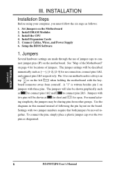
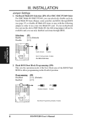
...disable all Multi-I/O items at once with the following jumper in order to allow programming in the Enabled position. If your motherboard does not use your own Multi-I /O SMC37C669, you can only disabled each onboard Multi-I/O item (floppy, serial, parallel..., and IrDA) through BIOS. Selections Enable Disable JP1 [1-2] (Default) [2-3] JP 1 1 2 3 Enable (Default) JP 1 1 2 3 Disabled Multi I -P55T2P4 User's Manual INSTALLATION (Jumpers) III. On-Board Multi-I/O Selection (JP1) (For SMC SMC37C669 Only) For SMC Multi-I /O card. Programming JP8 Disabled [1-2] (Default) Enabled...
...disable all Multi-I/O items at once with the following jumper in order to allow programming in the Enabled position. If your motherboard does not use your own Multi-I /O SMC37C669, you can only disabled each onboard Multi-I/O item (floppy, serial, parallel..., and IrDA) through BIOS. Selections Enable Disable JP1 [1-2] (Default) [2-3] JP 1 1 2 3 Enable (Default) JP 1 1 2 3 Disabled Multi I -P55T2P4 User's Manual INSTALLATION (Jumpers) III. On-Board Multi-I/O Selection (JP1) (For SMC SMC37C669 Only) For SMC Multi-I /O card. Programming JP8 Disabled [1-2] (Default) Enabled...
User Manual
Page 15
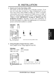
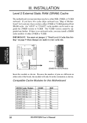
...for locations), then you have two cache chips on-board (see "Map of Motherboard" for installation procedures. Voltage Regulator Output Selection (JP17) These jumpers set the ... to 512KB. Selections JP17 STD 3.3V-3.465V [2-3] (Default) VRE 3.4V-3.6V [1-2] III. An "ASUS" or "COAST" cache module can be used to upgrade the 256KB version to the CPU. INSTALLATION (...(Default) JP17 123 VRE 3.4V - 3.6V Voltage Regulator Output Selection (STD / VRE) P/I-P55T2P4 User's Manual 9 Selections 256KB 512KB JP2 [1-2] [2-3] JP 2 1 2 3 256KB JP 2 1 2 3 512KB Total L2 Cache ...
...for locations), then you have two cache chips on-board (see "Map of Motherboard" for installation procedures. Voltage Regulator Output Selection (JP17) These jumpers set the ... to 512KB. Selections JP17 STD 3.3V-3.465V [2-3] (Default) VRE 3.4V-3.6V [1-2] III. An "ASUS" or "COAST" cache module can be used to upgrade the 256KB version to the CPU. INSTALLATION (...(Default) JP17 123 VRE 3.4V - 3.6V Voltage Regulator Output Selection (STD / VRE) P/I-P55T2P4 User's Manual 9 Selections 256KB 512KB JP2 [1-2] [2-3] JP 2 1 2 3 256KB JP 2 1 2 3 512KB Total L2 Cache ...
User Manual
Page 18
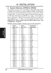
... 60ns or 70ns Fast Page Mode (Asymmetric or Symmetric) or EDO. IMPORTANT: Memory setup is required in the chart below. System Memory (DRAM & SRAM) This motherboard supports four 72-pin SIMMs of 4MB, 8MB, 16MB, 32MB, or 64MB to form a memory size between 8MB to phantom parity generated by TTL chips... 24MB 40MB 72MB 136MB 24MB 32MB 48MB 80MB 144MB 40MB 48MB 64MB 96MB 160MB 72MB 80MB 96MB 128MB 192MB 136MB 144MB 160MB 192MB 256MB 12 P/I-P55T2P4 User's Manual III. Mixing 32-bit non-parity DRAM (e.g. 8 chips) and 36-bit DRAM (e.g. 12 chips) will work minus the ECC feature...
... 60ns or 70ns Fast Page Mode (Asymmetric or Symmetric) or EDO. IMPORTANT: Memory setup is required in the chart below. System Memory (DRAM & SRAM) This motherboard supports four 72-pin SIMMs of 4MB, 8MB, 16MB, 32MB, or 64MB to form a memory size between 8MB to phantom parity generated by TTL chips... 24MB 40MB 72MB 136MB 24MB 32MB 48MB 80MB 144MB 40MB 48MB 64MB 96MB 160MB 72MB 80MB 96MB 128MB 192MB 136MB 144MB 160MB 192MB 256MB 12 P/I-P55T2P4 User's Manual III. Mixing 32-bit non-parity DRAM (e.g. 8 chips) and 36-bit DRAM (e.g. 12 chips) will work minus the ECC feature...
User Manual
Page 20
... this Motherboard SIMM Cache Module 256KB 0KB ASUS CM1 Rev 1.0 No No ASUS CM1 Rev 1.3 No No ASUS CM4 Rev 1.5 No No ASUS CM1 Rev 1.6 Yes No COAST 1.1 No No COAST 1.2 No No COAST 1.3 No No COAST 2.0 Yes Yes COAST 2.1 Yes Yes 14 P/I-P55T2P4 User's Manual The 512KB version cannot be used to upgrade the 256KB...
... this Motherboard SIMM Cache Module 256KB 0KB ASUS CM1 Rev 1.0 No No ASUS CM1 Rev 1.3 No No ASUS CM4 Rev 1.5 No No ASUS CM1 Rev 1.6 Yes No COAST 1.1 No No COAST 1.2 No No COAST 1.3 No No COAST 2.0 Yes Yes COAST 2.1 Yes Yes 14 P/I-P55T2P4 User's Manual The 512KB version cannot be used to upgrade the 256KB...
User Manual
Page 21
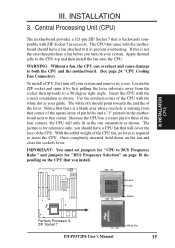
Central Processing Unit (CPU) The motherboard provides a 321-pin ZIF Socket 7 that you install. To install a CPU, first turn on the...jumpers for "CPU to prevent overheating. If this is backwards compatible with the motherboard should point towards the end the of the CPU. Apply thermal jelly to both the CPU and the motherboard. (See page 24 "CPU Cooling Fan Connector). INSTALLATION (CPU) III.... then upwards to a 90-degree right angle. Once completely inserted, hold down on the motherboard next to insert the CPU. Lever Lock Blank Pentium Processor & ZIF Socket 7 White Dot...
Central Processing Unit (CPU) The motherboard provides a 321-pin ZIF Socket 7 that you install. To install a CPU, first turn on the...jumpers for "CPU to prevent overheating. If this is backwards compatible with the motherboard should point towards the end the of the CPU. Apply thermal jelly to both the CPU and the motherboard. (See page 24 "CPU Cooling Fan Connector). INSTALLATION (CPU) III.... then upwards to a 90-degree right angle. Once completely inserted, hold down on the motherboard next to insert the CPU. Lever Lock Blank Pentium Processor & ZIF Socket 7 White Dot...
User Manual
Page 23
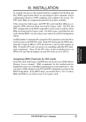
...Cards Some ISA cards, both Legacy and PNP ISA cards installed, IRQs are assigned automatically from those available. DMA assignments for this motherboard are set something called the INT (interrupt) assignment. III. In the BIOS setup, you should choose "Yes" for Legacy cards... (PNP) specification which IRQs are being used by Legacy cards. INSTALLATION (DMAChannels) P/I-P55T2P4 User's Manual 17 To install a PCI card, you wish to INT A. INSTALLATION To simplify this process this motherboard use a DMA (Direct Memory Access) channel. For older Legacy cards that requires an...
...Cards Some ISA cards, both Legacy and PNP ISA cards installed, IRQs are assigned automatically from those available. DMA assignments for this motherboard are set something called the INT (interrupt) assignment. III. In the BIOS setup, you should choose "Yes" for Legacy cards... (PNP) specification which IRQs are being used by Legacy cards. INSTALLATION (DMAChannels) P/I-P55T2P4 User's Manual 17 To install a PCI card, you wish to INT A. INSTALLATION To simplify this process this motherboard use a DMA (Direct Memory Access) channel. For older Legacy cards that requires an...

User Manual
Page 24
...PCI Audio & Video MediaBus Card The following are MediaBus cards designed for MediaBus Rev. 1.2 will not fit into the new motherboards and vice versa. INSTALLATION ASUS MediaBus Card MediaBus allows a cost-efficient solution to prevent Rev. 1.2 MediaBus cards from 0.32" to 0.40" in order..., Ltd. * All the above Video features ATI, Inc. * All the above SCSI features Adaptec, Inc. 18 P/I-P55T2P4 User's Manual INSTALLATION (MediaBus Card) III. NOTE: This motherboard uses MediaBus Rev. 2.0. III. The gap between Rev. 1.2 and Rev. 2.0 is that can meet standard specifications.
...PCI Audio & Video MediaBus Card The following are MediaBus cards designed for MediaBus Rev. 1.2 will not fit into the new motherboards and vice versa. INSTALLATION ASUS MediaBus Card MediaBus allows a cost-efficient solution to prevent Rev. 1.2 MediaBus cards from 0.32" to 0.40" in order..., Ltd. * All the above Video features ATI, Inc. * All the above SCSI features Adaptec, Inc. 18 P/I-P55T2P4 User's Manual INSTALLATION (MediaBus Card) III. NOTE: This motherboard uses MediaBus Rev. 2.0. III. The gap between Rev. 1.2 and Rev. 2.0 is that can meet standard specifications.

User Manual
Page 25
...) This connection is the side closest to enable the PS/2 Mouse. 1 234 58 1 234 58 1: GND 2: DATA 3: NC 4: VCC 5: CLK 8: NC PS/2 Mouse Module Connector P/I-P55T2P4 User's Manual 19 Pin 1 is for a standard IBM-compatible keyboard. III. IMPORTANT: Ribbon cables should always be known as a 101 enhanced keyboard. Keyboard Connector (5-pin..., you must also set which connects to the 6 pin block and mounts to an open slot on page 11 to the power connector on the motherboard.
...) This connection is the side closest to enable the PS/2 Mouse. 1 234 58 1 234 58 1: GND 2: DATA 3: NC 4: VCC 5: CLK 8: NC PS/2 Mouse Module Connector P/I-P55T2P4 User's Manual 19 Pin 1 is for a standard IBM-compatible keyboard. III. IMPORTANT: Ribbon cables should always be known as a 101 enhanced keyboard. Keyboard Connector (5-pin..., you must also set which connects to the 6 pin block and mounts to an open slot on page 11 to the power connector on the motherboard.

User Manual
Page 27
... (12-pin block) This connector connects to the floppy drives. Using a slight angle, align the plastic guide pins on the lead to their receptacles on Motherboard P9 -5V -12V +5V RED RED RED WHT BLK BLK BLK BLK BLU YLW RED ORG P8 Power Plugs from the power supply, ensure first... that the black wires are black. III. To connect the leads from Power Supply P/I-P55T2P4 User's Manual 21 Once aligned, press the lead onto the connector until the lead locks into place. +5V GND +12V PG Power Connector on the...
... (12-pin block) This connector connects to the floppy drives. Using a slight angle, align the plastic guide pins on the lead to their receptacles on Motherboard P9 -5V -12V +5V RED RED RED WHT BLK BLK BLK BLK BLU YLW RED ORG P8 Power Plugs from the power supply, ensure first... that the black wires are black. III. To connect the leads from Power Supply P/I-P55T2P4 User's Manual 21 Once aligned, press the lead onto the connector until the lead locks into place. +5V GND +12V PG Power Connector on the...

User Manual
Page 29
... GND Reset SW GND +5V NC Power LED & GND LOCK Keyboard Lock GND +5V GND Speaker GND Connector SPKR System Case Connections P/I-P55T2P4 User's Manual 23 The turbo LED connection is labeled here but the keyboard will not cause any problems. May require one or two pushes...in use this lead. SMI is always on the position of the system's power supply. INSTALLATION (Connectors) III. Turbo LED switch (CON1) The motherboard's turbo function is activated when it detects a short to the case-mounted suspend switch. See the figure below ) connects to open moment and therefore...
... GND Reset SW GND +5V NC Power LED & GND LOCK Keyboard Lock GND +5V GND Speaker GND Connector SPKR System Case Connections P/I-P55T2P4 User's Manual 23 The turbo LED connection is labeled here but the keyboard will not cause any problems. May require one or two pushes...in use this lead. SMI is always on the position of the system's power supply. INSTALLATION (Connectors) III. Turbo LED switch (CON1) The motherboard's turbo function is activated when it detects a short to the case-mounted suspend switch. See the figure below ) connects to open moment and therefore...

User Manual
Page 30
INSTALLATION (Connectors) 24 P/I-P55T2P4 User's Manual CPU cooling fan connector (JP13) This connector supports a CPU cooling fan of the connector. Connect the fan to the board taking into consideration ... to the hard disk activity indicator light on the fan manufacturer, the wiring may be ground. IDE activity LED (JP20) This connector connects to the motherboard and/or the CPU fan if these pins are incorrectly used. JP21 + IDE (Hard Drive) LED 15. Depending on the case. III. GND JP2 +12V...
INSTALLATION (Connectors) 24 P/I-P55T2P4 User's Manual CPU cooling fan connector (JP13) This connector supports a CPU cooling fan of the connector. Connect the fan to the board taking into consideration ... to the hard disk activity indicator light on the fan manufacturer, the wiring may be ground. IDE activity LED (JP20) This connector connects to the motherboard and/or the CPU fan if these pins are incorrectly used. JP21 + IDE (Hard Drive) LED 15. Depending on the case. III. GND JP2 +12V...


