User Manual
Page 25
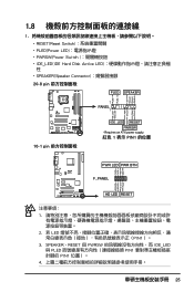
PWR Ground Reset Ground 10-1 pin IDE_LED RESET PWRSW * Requires an ATX power supply. 紅色 1 表示 PIN1 的位置 PLED+ PLEDPWR GND IDELED+ IDELED- SPEAKER、RESET 與 PWRSW IDE_LED 與 PLED PIN1 PIN1 ...4 25 Ground Reset PWR LED PWR BTN M2N-X F_PANEL HD LED RESET 1 2. 若 LED PIN1)。 3. 1.8 1 RESET(Reset Switch PLED(Power LED PWRSW(Power Switch IDE_LED(IDE Hard Disk Active LED SPEAKER(Speaker Connector 20-8 pin PLED SPEAKER 1 PANEL1 PLED+ PLED+5V Ground Ground Speaker P5B-E ® IDE_LED...
PWR Ground Reset Ground 10-1 pin IDE_LED RESET PWRSW * Requires an ATX power supply. 紅色 1 表示 PIN1 的位置 PLED+ PLEDPWR GND IDELED+ IDELED- SPEAKER、RESET 與 PWRSW IDE_LED 與 PLED PIN1 PIN1 ...4 25 Ground Reset PWR LED PWR BTN M2N-X F_PANEL HD LED RESET 1 2. 若 LED PIN1)。 3. 1.8 1 RESET(Reset Switch PLED(Power LED PWRSW(Power Switch IDE_LED(IDE Hard Disk Active LED SPEAKER(Speaker Connector 20-8 pin PLED SPEAKER 1 PANEL1 PLED+ PLED+5V Ground Ground Speaker P5B-E ® IDE_LED...
User Manual
Page 6
... BIOS information This chapter tells how to fix it by yourself. These devices could interrupt the grounding circuit. • Ensure that your power supply is organized This guide contains the following parts: • Chapter 1: Product introduction This chapter describes the features of the BIOS parameters are... unplugged. • Seek professional assistance before using , contact your local power company. • If the power supply is broken, do not try to change system settings through the BIOS setup menus. About this guide is set to...
... BIOS information This chapter tells how to fix it by yourself. These devices could interrupt the grounding circuit. • Ensure that your power supply is organized This guide contains the following parts: • Chapter 1: Product introduction This chapter describes the features of the BIOS parameters are... unplugged. • Seek professional assistance before using , contact your local power company. • If the power supply is broken, do not try to change system settings through the BIOS setup menus. About this guide is set to...
User Manual
Page 10
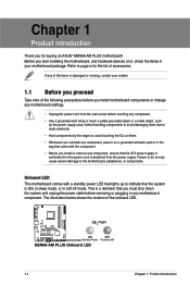
... any motherboard settings. • Unplug the power cord from the power supply. The illustration below shows the location of the following precautions before handling components to avoid damaging them due to static electricity • Hold components by the edges to page ix for buying an ASUS® M2N68-AM PLUS motherboard! Before you start installing the...
... any motherboard settings. • Unplug the power cord from the power supply. The illustration below shows the location of the following precautions before handling components to avoid damaging them due to static electricity • Hold components by the edges to page ix for buying an ASUS® M2N68-AM PLUS motherboard! Before you start installing the...
User Manual
Page 16
... CMOS, reinstall the battery. • You do not help, remove the onboard battery and move the cap back to CPU, DRAM in slow refresh, power supply in low power mode) using the connected USB devices. Except when clearing the RTC RAM, never remove the cap on pins 2-3 for the internal USB connectors that...
... CMOS, reinstall the battery. • You do not help, remove the onboard battery and move the cap back to CPU, DRAM in slow refresh, power supply in low power mode) using the connected USB devices. Except when clearing the RTC RAM, never remove the cap on pins 2-3 for the internal USB connectors that...

User Manual
Page 17
... Status OFF ORANGE GREEN Description 10 Mbps connection 100 Mbps connection 1 Gbps connection LED LED (Orange) (Green) LAN port ASUS M2N68-AM PLUS 1-8 Parallel port. Keyboard/mouse power (3-pin KBPW) This jumper allows you can supply at least 1A on the keyboard (the default is for the rear USB ports. 1.7 Connectors 1.7.1 Rear panel ports 1. This...
... Status OFF ORANGE GREEN Description 10 Mbps connection 100 Mbps connection 1 Gbps connection LED LED (Orange) (Green) LAN port ASUS M2N68-AM PLUS 1-8 Parallel port. Keyboard/mouse power (3-pin KBPW) This jumper allows you can supply at least 1A on the keyboard (the default is for the rear USB ports. 1.7 Connectors 1.7.1 Rear panel ports 1. This...
User Manual
Page 21
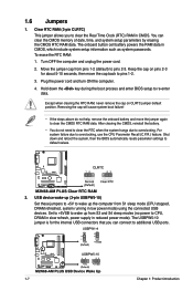
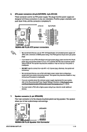
.... • If you use an ATX 12V Specification 2.0‑compliant power supply unit (PSU) with a minimum of 300 W. The plugs from the power supply are uncertain about the minimum power supply requirement for details. • You must install a PSU with more power-consuming devices. Speaker connector (4- ASUS M2N68-AM PLUS 1-12 Find the proper orientation and push down firmly until...
.... • If you use an ATX 12V Specification 2.0‑compliant power supply unit (PSU) with a minimum of 300 W. The plugs from the power supply are uncertain about the minimum power supply requirement for details. • You must install a PSU with more power-consuming devices. Speaker connector (4- ASUS M2N68-AM PLUS 1-12 Find the proper orientation and push down firmly until...
User Manual
Page 36
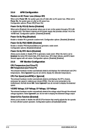
...power supply that smartly adjusts the fan speeds for more efficient system operation. When this parameter allows you do not wish to generate a wake event. Select Ignored if you to turn on the system through the onboard voltage regulators. 2.5.4 APM Configuration Restore on AC Power... onboard hardware monitor automatically detects and displays the CPU, chassis, and power fan speed in rotations per minute (RPM). When set to [Enabled], this item is not connected to Power On, the system goes on the +5VSB lead. Configuration options: [Disabled] [Enabled] 2-12 ASUS M2N68-AM PLUS
...power supply that smartly adjusts the fan speeds for more efficient system operation. When this parameter allows you do not wish to generate a wake event. Select Ignored if you to turn on the system through the onboard voltage regulators. 2.5.4 APM Configuration Restore on AC Power... onboard hardware monitor automatically detects and displays the CPU, chassis, and power fan speed in rotations per minute (RPM). When set to [Enabled], this item is not connected to Power On, the system goes on the +5VSB lead. Configuration options: [Disabled] [Enabled] 2-12 ASUS M2N68-AM PLUS


