User Manual
Page 9
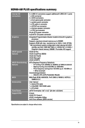
... 100 MHz up to 150 MHz at 1MHz increment - ix M2N68-AM PLUS specifications summary Internal I /O shield uATX Form factor: 9.6'' x 8.2'' (24.4cm x 20.8cm) Drivers ASUS PC Probe II ASUS LiveUpdate Utilitys Anti-Virus software (OEM version) *Specifications are subject...DDR 800 1GB x 2 / Althlon 64 x 2 4400+ / Graphich shared memory 256MB / Purevideo HD support ASUS Q-Fan ASUS CrashFree BIOS3 ASUS EZ Flash2 ASUS MyLogo2 ASUS AI NET2 SFS (Stepless Frequency Selection): - ASUS C.P.R. (CPU Parameter Recall) 8Mb Flash ROM, AMI BIOS, PnP, DMI2.0, WfM2.0, ACPI2.0, SMBIOS 2.5 User manual 1 x...
... 100 MHz up to 150 MHz at 1MHz increment - ix M2N68-AM PLUS specifications summary Internal I /O shield uATX Form factor: 9.6'' x 8.2'' (24.4cm x 20.8cm) Drivers ASUS PC Probe II ASUS LiveUpdate Utilitys Anti-Virus software (OEM version) *Specifications are subject...DDR 800 1GB x 2 / Althlon 64 x 2 4400+ / Graphich shared memory 256MB / Purevideo HD support ASUS Q-Fan ASUS CrashFree BIOS3 ASUS EZ Flash2 ASUS MyLogo2 ASUS AI NET2 SFS (Stepless Frequency Selection): - ASUS C.P.R. (CPU Parameter Recall) 8Mb Flash ROM, AMI BIOS, PnP, DMI2.0, WfM2.0, ACPI2.0, SMBIOS 2.5 User manual 1 x...
User Manual
Page 11
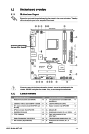
... pin SPDIF_OUT) 7. DDR2 DIMM slots 1-3 14. CPU fan connector (4-pin CPU_FAN) 1-11 12. Serial ATA connectors (7-pin SATA1-4) 1-9 15. Front panel audio connector (10-1 pin AAFP) Page 1-11 1-7 1-12 1-1 1-13 1-14 1-10 1-13 ASUS M2N68-AM PLUS 1-2 Place six screws into the chassis in the correct...(40-pin PRI-EIDE) 1-10 16. USB connectors (10-1 pin USB56 USB78, and USB 910) 2. Onboard LED 5. AM2/AM2+ CPU socket 1-3 13. Place this side towards the rear of the chassis. 1.2 1.2.1 Motherboard overview Motherboard layout Ensure that you install the motherboard into...
... pin SPDIF_OUT) 7. DDR2 DIMM slots 1-3 14. CPU fan connector (4-pin CPU_FAN) 1-11 12. Serial ATA connectors (7-pin SATA1-4) 1-9 15. Front panel audio connector (10-1 pin AAFP) Page 1-11 1-7 1-12 1-1 1-13 1-14 1-10 1-13 ASUS M2N68-AM PLUS 1-2 Place six screws into the chassis in the correct...(40-pin PRI-EIDE) 1-10 16. USB connectors (10-1 pin USB56 USB78, and USB 910) 2. Onboard LED 5. AM2/AM2+ CPU socket 1-3 13. Place this side towards the rear of the chassis. 1.2 1.2.1 Motherboard overview Motherboard layout Ensure that you install the motherboard into...
User Manual
Page 20
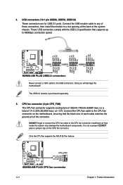
Never connect a 1394 cable to the CPU fan connector. Doing so will damage the motherboard! CPU fan connector (4-pin CPU_FAN) The CPU fan connector supports cooling fans of 350mA~740mA (8.88W max.) or a total of 1A~2.22A (26.64W max.) at the back of the ... connect the CPU fan cable to the USB connectors. Connect the USB module cable to the CPU fan connector on the CPU fan connector. Connect the CPU fan cable to any of the connector. USB connectors (10-1 pin USB56, USB78, USB910) These connectors are for USB 2.0 ports. Only the CPU fan supports the ASUS Q-Fan feature. ...
Never connect a 1394 cable to the CPU fan connector. Doing so will damage the motherboard! CPU fan connector (4-pin CPU_FAN) The CPU fan connector supports cooling fans of 350mA~740mA (8.88W max.) or a total of 1A~2.22A (26.64W max.) at the back of the ... connect the CPU fan cable to the USB connectors. Connect the USB module cable to the CPU fan connector on the CPU fan connector. Connect the CPU fan cable to any of the connector. USB connectors (10-1 pin USB56, USB78, USB910) These connectors are for USB 2.0 ports. Only the CPU fan supports the ASUS Q-Fan feature. ...
User Manual
Page 36
... this item is not connected to display the detected speed. Configuration options: [Disabled] [Enabled] 2.5.5 HW Monitor Configuration CPU Temperature [xxxºC/xxxºF] MB Temperature [xxxºC/xxxºF] The onboard hardware monitor automatically detects and displays the motherboard and... [Disabled] When set values. This feature requires an ATX power supply that smartly adjusts the fan speeds for more efficient system operation. Configuration options: [Disabled] [Enabled] 2-12 ASUS M2N68-AM PLUS When set to Power Off, the system goes into off state after an AC power loss....
... this item is not connected to display the detected speed. Configuration options: [Disabled] [Enabled] 2.5.5 HW Monitor Configuration CPU Temperature [xxxºC/xxxºF] MB Temperature [xxxºC/xxxºF] The onboard hardware monitor automatically detects and displays the motherboard and... [Disabled] When set values. This feature requires an ATX power supply that smartly adjusts the fan speeds for more efficient system operation. Configuration options: [Disabled] [Enabled] 2-12 ASUS M2N68-AM PLUS When set to Power Off, the system goes into off state after an AC power loss....


