H87-PRO User's Manual
Page 12
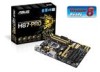
..."x 8.6" (30.5cm x 21.8cm) Specifications are for reference only. Package contents Check your motherboard package for the following items. User Manual H87-PRO ASUS H87-PRO motherboard User manual Support DVD 2 x Serial ATA 6.0 Gb/s cables 1 x ASUS Q-Shield • If any of the items are damaged or missing, contact your retailer. • The illustrations above are subject...
..."x 8.6" (30.5cm x 21.8cm) Specifications are for reference only. Package contents Check your motherboard package for the following items. User Manual H87-PRO ASUS H87-PRO motherboard User manual Support DVD 2 x Serial ATA 6.0 Gb/s cables 1 x ASUS Q-Shield • If any of the items are damaged or missing, contact your retailer. • The illustrations above are subject...

H87-PRO User's Manual
Page 15
... 1333 / 1066 MHz Support The motherboard supports the dual-channel DDR3 memory that optimizes PCIe allocation in the LGA1150 package. Chapter 1 ASUS H87-PRO 1-1 It provides great graphics and system performance with its GPU, dual-channel DDR3 memory slots and PCI Express 2.0/3.0 expansion slots. It...delivers up to meet the higher bandwidth requirements of 3D graphics, multimedia and Internet applications. Native SATA 6.0 Gb/s support With Intel® H87 Express Chipset natively support for Intel® 4th Generation Core™ i7 / Core™ i5 / Core™ i3, Pentium®,...
... 1333 / 1066 MHz Support The motherboard supports the dual-channel DDR3 memory that optimizes PCIe allocation in the LGA1150 package. Chapter 1 ASUS H87-PRO 1-1 It provides great graphics and system performance with its GPU, dual-channel DDR3 memory slots and PCI Express 2.0/3.0 expansion slots. It...delivers up to meet the higher bandwidth requirements of 3D graphics, multimedia and Internet applications. Native SATA 6.0 Gb/s support With Intel® H87 Express Chipset natively support for Intel® 4th Generation Core™ i7 / Core™ i5 / Core™ i3, Pentium®,...

H87-PRO User's Manual
Page 17
.... AI Suite 3 With its elegant appearance. MemOK! ASUS Anti-Surge Protection This special design protects expensive devices and the motherboard from damage caused by power surges from switching power supply unit (PSU). Chapter 1 ASUS H87-PRO 1-3 ESD Protect your bandwidth and allows you an extremely... silent and cooling experience with ESD Guards. ASUS ESD Guards clamp the ESD voltage and shunt the majority of the chipset ...
.... AI Suite 3 With its elegant appearance. MemOK! ASUS Anti-Surge Protection This special design protects expensive devices and the motherboard from damage caused by power surges from switching power supply unit (PSU). Chapter 1 ASUS H87-PRO 1-3 ESD Protect your bandwidth and allows you an extremely... silent and cooling experience with ESD Guards. ASUS ESD Guards clamp the ESD voltage and shunt the majority of the chipset ...

H87-PRO User's Manual
Page 19
... and ErP requires products to meet certain energy efficiency requirement in line with the highest quality home theater experience. Chapter 1 ASUS H87-PRO 1-5 1.1.6 Other special features DisplayPort Support DisplayPort is a digital display interface standard that delivers up to reduce carbon footprint of ...of creating environment-friendly and energy-efficient products through the connected DisplayPort cable with your 3D display, then you with ASUS vision of the following precautions before you install motherboard components or change any motherboard settings. • Unplug the ...
... and ErP requires products to meet certain energy efficiency requirement in line with the highest quality home theater experience. Chapter 1 ASUS H87-PRO 1-5 1.1.6 Other special features DisplayPort Support DisplayPort is a digital display interface standard that delivers up to reduce carbon footprint of ...of creating environment-friendly and energy-efficient products through the connected DisplayPort cable with your 3D display, then you with ASUS vision of the following precautions before you install motherboard components or change any motherboard settings. • Unplug the ...

H87-PRO User's Manual
Page 21
...SPDIF_OUT) 15. Onboard LED (SB_PWR) Page 1-20 1-22 1-21 1-8 1-14 1-15 1-9 1-13 1-18 1-17 1-15 1-23 1-19 1-19 1-20 1-15 Chapter 1 ASUS H87-PRO 1-7 Layout contents Connectors/Jumpers/Buttons and switches/Slots 1. CPU & Chassis fan connectors (4-pin CPU_FAN, 4-pin CHA_FAN1~3) 4. USB 3.0 connector (20-1 pin USB3_12) 10. Front ...power connectors (24-pin EATXPWR, 8-pin EATX12V) 3. System panel connector (20-8 pin PANEL) 13. GPU Boost LED 7. Intel® H87 Serial ATA 6.0 Gb/s connectors (7-pin SATA 6G_1~6) 11. GPU Boost switch 6. Serial port connectors (10-1 pin COM1) 2.
...SPDIF_OUT) 15. Onboard LED (SB_PWR) Page 1-20 1-22 1-21 1-8 1-14 1-15 1-9 1-13 1-18 1-17 1-15 1-23 1-19 1-19 1-20 1-15 Chapter 1 ASUS H87-PRO 1-7 Layout contents Connectors/Jumpers/Buttons and switches/Slots 1. CPU & Chassis fan connectors (4-pin CPU_FAN, 4-pin CHA_FAN1~3) 4. USB 3.0 connector (20-1 pin USB3_12) 10. Front ...power connectors (24-pin EATXPWR, 8-pin EATX12V) 3. System panel connector (20-8 pin PANEL) 13. GPU Boost LED 7. Intel® H87 Serial ATA 6.0 Gb/s connectors (7-pin SATA 6G_1~6) 11. GPU Boost switch 6. Serial port connectors (10-1 pin COM1) 2.

H87-PRO User's Manual
Page 23
DO NOT install a DDR or DDR2 memory module to the DDR3 slot. DIMM_A1 DIMM_A2 DIMM_B1 DIMM_B2 H87-PRO H87-PRO 240-pin DDR3 DIMM sockets Recommended memory configurations DIMM_A1 DIMM_A2 DIMM_B2 DIMM_A1 DIMM_A2 DIMM_B1 DIMM_B2 Chapter 1 ASUS H87-PRO 1-9 1.2.4 System memory The motherboard comes with four Double Data Rate 3 (DDR3) Dual Inline Memory Modules (DIMM) slots. A DDR3 module is notched differently from a DDR or DDR2 module.
DO NOT install a DDR or DDR2 memory module to the DDR3 slot. DIMM_A1 DIMM_A2 DIMM_B1 DIMM_B2 H87-PRO H87-PRO 240-pin DDR3 DIMM sockets Recommended memory configurations DIMM_A1 DIMM_A2 DIMM_B2 DIMM_A1 DIMM_A2 DIMM_B1 DIMM_B2 Chapter 1 ASUS H87-PRO 1-9 1.2.4 System memory The motherboard comes with four Double Data Rate 3 (DDR3) Dual Inline Memory Modules (DIMM) slots. A DDR3 module is notched differently from a DDR or DDR2 module.

H87-PRO User's Manual
Page 25
Failure to do so may cause you physical injury and damage motherboard components. 1.2.5 Expansion slots Unplug the power cord before adding or removing expansion cards. H87-PRO Slot No. 1 2 3 4 5 6 7 Slot Description PCIe 2.0 x1_1 slot PCIe 3.0 x16_1 slot [Yellow] (at x16 mode) PCIe 2.0 x1_2 slot PCI1 slot PCIe 2.0 x16_2 slot [Dark brown] (at x4 mode, compatible with PCIe x1 and x4 devices) PCI2 slot PCI3 slot ASUS H87-PRO 1-11 Chapter 1
Failure to do so may cause you physical injury and damage motherboard components. 1.2.5 Expansion slots Unplug the power cord before adding or removing expansion cards. H87-PRO Slot No. 1 2 3 4 5 6 7 Slot Description PCIe 2.0 x1_1 slot PCIe 3.0 x16_1 slot [Yellow] (at x16 mode) PCIe 2.0 x1_2 slot PCI1 slot PCIe 2.0 x16_2 slot [Dark brown] (at x4 mode, compatible with PCIe x1 and x4 devices) PCI2 slot PCI3 slot ASUS H87-PRO 1-11 Chapter 1
H87-PRO User's Manual
Page 27
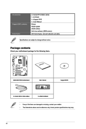
...compatibility tuning for overclockers and gamers who continually change settings to section 1.2.8 Onboard LEDs for the exact location of failsafe settings. H87-PRO H87-PRO MemOK! To stop memory tuning, turn off the computer and replace DIMMs during POST reminding you that the BIOS has been ... with ones recommended in the Memory QVL (Qualified Vendors Lists) in this user manual or on the ASUS website at www.asus.com after using the MemOK! Chapter 1 ASUS H87-PRO 1-13 to boot and load BIOS default settings. A message will appear during the tuning process, the...
...compatibility tuning for overclockers and gamers who continually change settings to section 1.2.8 Onboard LEDs for the exact location of failsafe settings. H87-PRO H87-PRO MemOK! To stop memory tuning, turn off the computer and replace DIMMs during POST reminding you that the BIOS has been ... with ones recommended in the Memory QVL (Qualified Vendors Lists) in this user manual or on the ASUS website at www.asus.com after using the MemOK! Chapter 1 ASUS H87-PRO 1-13 to boot and load BIOS default settings. A message will appear during the tuning process, the...
H87-PRO User's Manual
Page 29
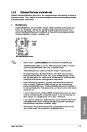
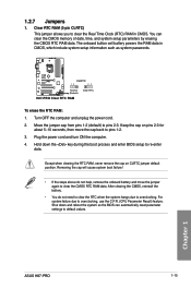
... Clear RTC To erase the RTC RAM: 1. Move the jumper cap from pins 1-2 (default) to pins 1-2. 3. Keep the cap on CLRTC jumper default position. Chapter 1 ASUS H87-PRO 1-15 Clear RTC RAM (3-pin CLRTC) This jumper allows you to clear the CMOS RTC RAM data. The onboard button cell battery powers the RAM...
... Clear RTC To erase the RTC RAM: 1. Move the jumper cap from pins 1-2 (default) to pins 1-2. 3. Keep the cap on CLRTC jumper default position. Chapter 1 ASUS H87-PRO 1-15 Clear RTC RAM (3-pin CLRTC) This jumper allows you to clear the CMOS RTC RAM data. The onboard button cell battery powers the RAM...

H87-PRO User's Manual
Page 31
... SATA6G_5 GND RSATA_TXP6 RSATA_TXN6 GND RSATA_RXN6 RSATA_RXP6 GND GND RSATA_TXP5 RSATA_TXN5 GND RSATA_RXN5 RSATA_RXP5 GND H87-PRO SATA6G_4 SATA6G_3 GND RSATA_RXP4 RSATA_RXN4 GND RSATA_TXN4 RSATA_TXP4 GND GND RSATA_RXP3 RSATA_RXN3 GND RSATA_TXN3 RSATA_TXP3 GND H87-PRO SATA 6.0Gb/s connectors Chapter 1 ASUS H87-PRO 1-17 This user-friendly design provides an easy way to identify problems related to the...
... SATA6G_5 GND RSATA_TXP6 RSATA_TXN6 GND RSATA_RXN6 RSATA_RXP6 GND GND RSATA_TXP5 RSATA_TXN5 GND RSATA_RXN5 RSATA_RXP5 GND H87-PRO SATA6G_4 SATA6G_3 GND RSATA_RXP4 RSATA_RXN4 GND RSATA_TXN4 RSATA_TXP4 GND GND RSATA_RXP3 RSATA_RXN3 GND RSATA_TXN3 RSATA_TXP3 GND H87-PRO SATA 6.0Gb/s connectors Chapter 1 ASUS H87-PRO 1-17 This user-friendly design provides an easy way to identify problems related to the...

H87-PRO User's Manual
Page 33
...USB 2.0 ports under Windows® 7. 4. Doing so will damage the motherboard! • The USB 2.0 module is for USB 2.0 ports. ASUS H87-PRO 1-19 Connect the USB module cable to any of these connectors, then install the module to a slot opening at the back of the system ...chassis. +5V SPDIFOUT GND Chapter 1 H87-PRO SPDIF_OUT H87-PRO Digital audio connector The S/PDIF module is purchased separately. We recommend you to install the related driver to the USB connectors. Digital...
...USB 2.0 ports under Windows® 7. 4. Doing so will damage the motherboard! • The USB 2.0 module is for USB 2.0 ports. ASUS H87-PRO 1-19 Connect the USB module cable to any of these connectors, then install the module to a slot opening at the back of the system ...chassis. +5V SPDIFOUT GND Chapter 1 H87-PRO SPDIF_OUT H87-PRO Digital audio connector The S/PDIF module is purchased separately. We recommend you to install the related driver to the USB connectors. Digital...

H87-PRO User's Manual
Page 35
... on the motherboard, ensuring that you plug the rear chassis fan cable to the fan connectors. 7. Chapter 1 ASUS H87-PRO 1-21 These are not jumpers! Insufficient air flow inside the system may damage the motherboard components. CPU_FAN CHA_FAN2 CPU...IN CPU FAN PWR GND CHA FAN PWM CHA FAN IN CHA FAN PWR GND H87-PRO CHA_FAN1 CHA_FAN3 GND CHA FAN PWR CHA FAN IN CHA FAN PWM CHA FAN PWM CHA FAN IN ...CHA FAN PWR GND H87-PRO Fan connectors • DO NOT forget to connect the fan cables to the motherboard connector labeled ...
... on the motherboard, ensuring that you plug the rear chassis fan cable to the fan connectors. 7. Chapter 1 ASUS H87-PRO 1-21 These are not jumpers! Insufficient air flow inside the system may damage the motherboard components. CPU_FAN CHA_FAN2 CPU...IN CPU FAN PWR GND CHA FAN PWM CHA FAN IN CHA FAN PWR GND H87-PRO CHA_FAN1 CHA_FAN3 GND CHA FAN PWR CHA FAN IN CHA FAN PWM CHA FAN PWM CHA FAN IN ...CHA FAN PWR GND H87-PRO Fan connectors • DO NOT forget to connect the fan cables to the motherboard connector labeled ...
H87-PRO User's Manual
Page 37
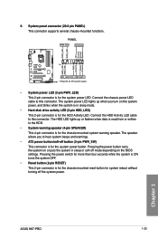
PANEL PWR_LED SPEAKER PWR_LED PWR_LED +5V Ground Ground Speaker HDD_LED HDD_LED PWR Ground Reset Ground PIN 1 H87-PRO HDD_LED PWR_SW RESET * Requires an ATX power supply H87-PRO System panel connector • System power LED (2-pin PWR_LED) This 2-pin connector is for system reboot without turning off the ...on the BIOS settings. 9. The system power LED lights up or flashes when data is read from or written to this connector. Chapter 1 ASUS H87-PRO 1-23 Connect the chassis power LED cable to the HDD. • System warning speaker (4-pin SPEAKER) This 4-pin connector is for the ...
PANEL PWR_LED SPEAKER PWR_LED PWR_LED +5V Ground Ground Speaker HDD_LED HDD_LED PWR Ground Reset Ground PIN 1 H87-PRO HDD_LED PWR_SW RESET * Requires an ATX power supply H87-PRO System panel connector • System power LED (2-pin PWR_LED) This 2-pin connector is for system reboot without turning off the ...on the BIOS settings. 9. The system power LED lights up or flashes when data is read from or written to this connector. Chapter 1 ASUS H87-PRO 1-23 Connect the chassis power LED cable to the HDD. • System warning speaker (4-pin SPEAKER) This 4-pin connector is for the ...

H87-PRO User's Manual
Page 38
The motherboard layout may vary with models, but the installation steps are for all models. 1. Chapter 2: Basic Installation Basic Installation 2.1 Building your PC system 2 2.1.1 Motherboard installation The diagrams in this section are the same for reference only. Install the ASUS Q-Shield to the chassis rear I/O panel. Chapter 2 ASUS H87-PRO 2-1
The motherboard layout may vary with models, but the installation steps are for all models. 1. Chapter 2: Basic Installation Basic Installation 2.1 Building your PC system 2 2.1.1 Motherboard installation The diagrams in this section are the same for reference only. Install the ASUS Q-Shield to the chassis rear I/O panel. Chapter 2 ASUS H87-PRO 2-1
H87-PRO User's Manual
Page 40
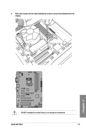
3. ASUS H87-PRO 2-3 Place nine screws into the holes indicated by circles to secure the motherboard to the chassis. Doing so can damage the motherboard. Chapter 2 H87-PRO DO NOT overtighten the screws!
3. ASUS H87-PRO 2-3 Place nine screws into the holes indicated by circles to secure the motherboard to the chassis. Doing so can damage the motherboard. Chapter 2 H87-PRO DO NOT overtighten the screws!

H87-PRO User's Manual
Page 42
To install the CPU heatsink and fan assembly 1 A 2 B B A Chapter 2 ASUS H87-PRO 2-5 4 5 2.1.3 CPU heatsink and fan assembly installation Apply the Thermal Interface Material to the CPU heatsink and CPU before you install the heatsink and fan if necessary.
To install the CPU heatsink and fan assembly 1 A 2 B B A Chapter 2 ASUS H87-PRO 2-5 4 5 2.1.3 CPU heatsink and fan assembly installation Apply the Thermal Interface Material to the CPU heatsink and CPU before you install the heatsink and fan if necessary.

H87-PRO User's Manual
Page 44
2.1.4 1 DIMM installation 2 3 To remove a DIMM B A A ASUS H87-PRO 2-7 Chapter 2
2.1.4 1 DIMM installation 2 3 To remove a DIMM B A A ASUS H87-PRO 2-7 Chapter 2

H87-PRO User's Manual
Page 46
2.1.6 1 SATA device connection OR 2 OR Chapter 2 ASUS H87-PRO 2-9
2.1.6 1 SATA device connection OR 2 OR Chapter 2 ASUS H87-PRO 2-9

H87-PRO User's Manual
Page 48
2.1.8 Expansion Card installation To install PCIe x16 cards To install PCIe x1 cards To install PCI cards Chapter 2 ASUS H87-PRO 2-11
2.1.8 Expansion Card installation To install PCIe x16 cards To install PCIe x1 cards To install PCI cards Chapter 2 ASUS H87-PRO 2-11

H87-PRO User's Manual
Page 50
DVI-D port 9. HDMI port 10. Intel® USB 3.0 ports support ASUS USB 3.0 Boost. 5. LAN (RJ-45) port* 6. Chapter 2 ASUS H87-PRO 2-13 Optical S/PDIF OUT port 3. DisplayPort 10. Audio I /O connection 1 2 3 4 5 6 11 10 9 8 7 Rear panel connectors 1. PS/2 Keyboard/Mouse combo port 2. 2.3 Motherboard rear and audio connections 2.3.1 Rear I /O ... page for LAN port LEDs, and audio port definitions. Bottom part supports USB BIOS Flashback. 8. Video Graphics Adapter (VGA) port 4. Intel® USB 3.0 ports support ASUS USB 3.0 Boost.
DVI-D port 9. HDMI port 10. Intel® USB 3.0 ports support ASUS USB 3.0 Boost. 5. LAN (RJ-45) port* 6. Chapter 2 ASUS H87-PRO 2-13 Optical S/PDIF OUT port 3. DisplayPort 10. Audio I /O connection 1 2 3 4 5 6 11 10 9 8 7 Rear panel connectors 1. PS/2 Keyboard/Mouse combo port 2. 2.3 Motherboard rear and audio connections 2.3.1 Rear I /O ... page for LAN port LEDs, and audio port definitions. Bottom part supports USB BIOS Flashback. 8. Video Graphics Adapter (VGA) port 4. Intel® USB 3.0 ports support ASUS USB 3.0 Boost.


