User Guide
Page 4
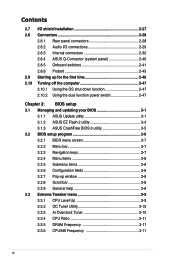
... utility 3-1 3.1.2 ASUS EZ Flash 2 utility 3-4 3.1.3 ASUS CrashFree BIOS 3 utility 3-5 3.2 BIOS setup program 3-6 3.2.1 BIOS menu screen 3-7 3.2.2 Menu bar 3-7 3.2.3 Navigation keys 3-7 3.2.4 Menu items 3-8 3.2.5 Submenu items 3-8 3.2.6 Configuration fields 3-8 3.2.7 Pop-up window 3-8 3.2.8 Scroll bar 3-8 3.2.9 General help 3-8 3.3 Extreme Tweaker menu 3-9 3.3.1 CPU Level Up 3-9 3.3.2 OC Tuner Utility 3-10 3.3.3 Ai Overclock Tuner 3-10 3.3.4 CPU Ratio 3-11 3.3.5 DRAM Frequency 3-11 3.3.6 CPU/NB Frequency 3-11 iv
... utility 3-1 3.1.2 ASUS EZ Flash 2 utility 3-4 3.1.3 ASUS CrashFree BIOS 3 utility 3-5 3.2 BIOS setup program 3-6 3.2.1 BIOS menu screen 3-7 3.2.2 Menu bar 3-7 3.2.3 Navigation keys 3-7 3.2.4 Menu items 3-8 3.2.5 Submenu items 3-8 3.2.6 Configuration fields 3-8 3.2.7 Pop-up window 3-8 3.2.8 Scroll bar 3-8 3.2.9 General help 3-8 3.3 Extreme Tweaker menu 3-9 3.3.1 CPU Level Up 3-9 3.3.2 OC Tuner Utility 3-10 3.3.3 Ai Overclock Tuner 3-10 3.3.4 CPU Ratio 3-11 3.3.5 DRAM Frequency 3-11 3.3.6 CPU/NB Frequency 3-11 iv
User Guide
Page 7
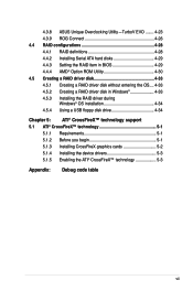
4.3.8 ASUS Unique Overclocking Utility-TurboV EVO......... 4-23 4.3.9 ROG Connect 4-26 4.4 RAID configurations 4-28 4.4.1 RAID definitions 4-28 4.4.2 Installing Serial ATA hard disks 4-29 4.4.3 Setting the RAID item in BIOS 4-29 4.4.4 AMD® Option ROM Utility 4-30 4.5 Creating a RAID driver disk 4-33 4.5.1 Creating a RAID driver disk without entering the OS.... 4-33 4.5.2 Creating a RAID driver disk...
4.3.8 ASUS Unique Overclocking Utility-TurboV EVO......... 4-23 4.3.9 ROG Connect 4-26 4.4 RAID configurations 4-28 4.4.1 RAID definitions 4-28 4.4.2 Installing Serial ATA hard disks 4-29 4.4.3 Setting the RAID item in BIOS 4-29 4.4.4 AMD® Option ROM Utility 4-30 4.5 Creating a RAID driver disk 4-33 4.5.1 Creating a RAID driver disk without entering the OS.... 4-33 4.5.2 Creating a RAID driver disk...
User Guide
Page 10
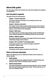
... sources for additional information and for the LCD Poster. ASUS websites The ASUS website provides updated information on the motherboard. • Chapter 3: BIOS setup This chapter tells how to change system settings through the BIOS Setup menus. How this guide This user guide contains...The Appendix lists the debug code table for product and software updates. 1. Detailed descriptions of the BIOS parameters are not part of the switches, jumpers, and connectors on ASUS hardware and software products. These documents are also provided. • Chapter 4: Software support This ...
... sources for additional information and for the LCD Poster. ASUS websites The ASUS website provides updated information on the motherboard. • Chapter 3: BIOS setup This chapter tells how to change system settings through the BIOS Setup menus. How this guide This user guide contains...The Appendix lists the debug code table for product and software updates. 1. Detailed descriptions of the BIOS parameters are not part of the switches, jumpers, and connectors on ASUS hardware and software products. These documents are also provided. • Chapter 4: Software support This ...
User Guide
Page 13
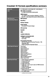
... port 1 x S/PDIF Out (Optical) 8-channel Audio I /O is also for ROG connect) ROG Connect GameFirst Extreme Tweaker Power Design - 8+2 phase CPU power design CPU Level Up MemOK! COP EX (Component Overheat Protection - EX) - O.C Profile Overclocking Protection - ASUS TurboV EVO - Crosshair IV Formula specifications summary IEEE 1394 USB ROG Exclusive Overclocking Features Other Special Features Back...
... port 1 x S/PDIF Out (Optical) 8-channel Audio I /O is also for ROG connect) ROG Connect GameFirst Extreme Tweaker Power Design - 8+2 phase CPU power design CPU Level Up MemOK! COP EX (Component Overheat Protection - EX) - O.C Profile Overclocking Protection - ASUS TurboV EVO - Crosshair IV Formula specifications summary IEEE 1394 USB ROG Exclusive Overclocking Features Other Special Features Back...
User Guide
Page 14
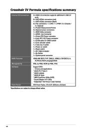
... applications * ASUS PC Probe II * ASUS Update * ASUS AI Suite * AMD OverDrive Utility (AOD) * Sound Blaster X-Fi Utility * Kaspersky® Anti-Virus (1-year license) ATX Form Factor, 12"x 9.6" (30.5cm x 24.5cm) *Specifications are subject to change without notice. Crosshair IV Formula specifications summary Internal I/O Connectors BIOS Features Manageability... key II switch 1 x Power on switch 1 x Reset switch 1 x OC Station Header 1 x Go Button 1 x System panel connector 16Mb AMI BIOS, PnP, DMI2.0, WfM2.0, SM BIOS 2.4, ACPI2.0a Multi-Language BIOS WOL by PME, WOR by PME, PXE Support DVD: -
... applications * ASUS PC Probe II * ASUS Update * ASUS AI Suite * AMD OverDrive Utility (AOD) * Sound Blaster X-Fi Utility * Kaspersky® Anti-Virus (1-year license) ATX Form Factor, 12"x 9.6" (30.5cm x 24.5cm) *Specifications are subject to change without notice. Crosshair IV Formula specifications summary Internal I/O Connectors BIOS Features Manageability... key II switch 1 x Power on switch 1 x Reset switch 1 x OC Station Header 1 x Go Button 1 x System panel connector 16Mb AMI BIOS, PnP, DMI2.0, WfM2.0, SM BIOS 2.4, ACPI2.0a Multi-Language BIOS WOL by PME, WOR by PME, PXE Support DVD: -
User Guide
Page 22
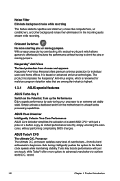
...ASUS Core Unlocker simplifies the activation of a button. Processor The ultimate O.C. Auto tuning intelligently pushes the system to unleash extra processing capabilities. Turbo Key boosts performance with just a press of a latent AMD CPU-with just one touch; enjoy an instant performance boost by auto-tuning your processor to an extreme... overclockers to effortlessly fine-tune the performance without performing complicating BIOS changes. It is renowned for individual users and home offices. ASUS TurboV EVO The ultimate O.C. record. 1-6 Chapter 1: Product Introduction
...ASUS Core Unlocker simplifies the activation of a button. Processor The ultimate O.C. Auto tuning intelligently pushes the system to unleash extra processing capabilities. Turbo Key boosts performance with just a press of a latent AMD CPU-with just one touch; enjoy an instant performance boost by auto-tuning your processor to an extreme... overclockers to effortlessly fine-tune the performance without performing complicating BIOS changes. It is renowned for individual users and home offices. ASUS TurboV EVO The ultimate O.C. record. 1-6 Chapter 1: Product Introduction
User Guide
Page 23
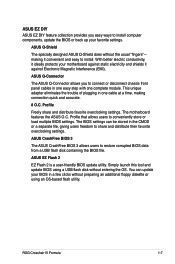
... settings. ASUS CrashFree BIOS 3 The ASUS CrashFree BIOS 3 allows users to conveniently store or load multiple BIOS settings. Profile that allows users to restore corrupted BIOS data from a USB flash disk containing the BIOS file. With better electric conductivity, it ideally protects your BIOS in a few clicks without entering the OS. The motherboard features the ASUS O.C. ROG Crosshair IV Formula 1-7 making...
... settings. ASUS CrashFree BIOS 3 The ASUS CrashFree BIOS 3 allows users to conveniently store or load multiple BIOS settings. Profile that allows users to restore corrupted BIOS data from a USB flash disk containing the BIOS file. With better electric conductivity, it ideally protects your BIOS in a few clicks without entering the OS. The motherboard features the ASUS O.C. ROG Crosshair IV Formula 1-7 making...
User Guide
Page 28
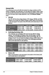
... voltage displays: CPU Voltage, VDDNB, and VDDA Voltage; Refer to display in BIOS. Northbridge/Southbridge LEDs The northbridge and southbridge LEDs each have two different voltage displays. You can select the voltage to 3.3 Extreme Tweaker menu. 1. Refer to the illustration on the next page for the location... the location of the memory LED and the table below for LED definition. For more information about voltage adjustment, refer to display in BIOS. The northbridge LED displays either the SB Voltage, SB 1.2V Voltage, or the HT. Onboard LEDs The motherboard comes with LEDs that...
... voltage displays: CPU Voltage, VDDNB, and VDDA Voltage; Refer to display in BIOS. Northbridge/Southbridge LEDs The northbridge and southbridge LEDs each have two different voltage displays. You can select the voltage to 3.3 Extreme Tweaker menu. 1. Refer to the illustration on the next page for the location... the location of the memory LED and the table below for LED definition. For more information about voltage adjustment, refer to display in BIOS. The northbridge LED displays either the SB Voltage, SB 1.2V Voltage, or the HT. Onboard LEDs The motherboard comes with LEDs that...
User Guide
Page 49
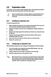
... expansion card, read the documentation that you intend to the tables on the system and change the necessary BIOS settings, if any. Ensure to the card. Assign an IRQ to unplug the power cord before adding ... the drivers support "Share IRQ" or that they support. Remove the system unit cover (if your motherboard is completely seated on BIOS setup. 2. Keep the screw for later use . Refer to use . 4. Otherwise, conflicts will arise between the two PCI ... and the expansion cards that the cards do so may need IRQ assignments. ROG Crosshair IV Formula 2-23
... expansion card, read the documentation that you intend to the tables on the system and change the necessary BIOS settings, if any. Ensure to the card. Assign an IRQ to unplug the power cord before adding ... the drivers support "Share IRQ" or that they support. Remove the system unit cover (if your motherboard is completely seated on BIOS setup. 2. Keep the screw for later use . Refer to use . 4. Otherwise, conflicts will arise between the two PCI ... and the expansion cards that the cards do so may need IRQ assignments. ROG Crosshair IV Formula 2-23
User Guide
Page 52
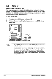
...RTC RAM data. To erase the RTC RAM: 1. With the C.P.R. (CPU Parameter Recall) feature, shut down the key during the boot process and enter BIOS setup to re-enter data. • The clr CMOS switch will not function if the CLRTC_SW jumper is moved to the Disable position. • Ensure... to re-enter your previous BIOS settings after you easily clear the system setup information such as system passwords. 2.6 Jumper Clear RTC RAM (3-pin CLRTC_SW) This jumper allows you to enable...
...RTC RAM data. To erase the RTC RAM: 1. With the C.P.R. (CPU Parameter Recall) feature, shut down the key during the boot process and enter BIOS setup to re-enter data. • The clr CMOS switch will not function if the CLRTC_SW jumper is moved to the Disable position. • Ensure... to re-enter your previous BIOS settings after you easily clear the system setup information such as system passwords. 2.6 Jumper Clear RTC RAM (3-pin CLRTC_SW) This jumper allows you to enable...
User Guide
Page 54
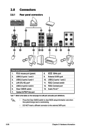
... Ports** *and **: Refer to the tables on the next page for LAN port and audio port definitions. • Press the Clear CMOS switch to clear BIOS setup information only when the system hangs due to overclocking. • DO NOT insert a different connector to the external SATA port. 2-28 Chapter 2: Hardware information...
... Ports** *and **: Refer to the tables on the next page for LAN port and audio port definitions. • Press the Clear CMOS switch to clear BIOS setup information only when the system hangs due to overclocking. • DO NOT insert a different connector to the external SATA port. 2-28 Chapter 2: Hardware information...
User Guide
Page 58
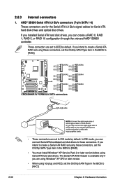
... intend to create a Serial ATA RAID set using these connectors, set the Onchip SATA Type item in the BIOS to [RAID]. • These connectors are set the OnChip SATA Type item in the BIOS to [RAID]. • You must install Windows® XP Service Pack 2 or later version before using ... disc drives. The Serial ATA RAID feature is available only if you intend to create a Serial ATA RAID set the OnChip SATA Type in the BIOS to [AHCI]. 2-32 Chapter 2: Hardware information If you installed Serial ATA hard disk drives, you can create a RAID 0, RAID 1, RAID 5, or RAID 10 ...
... intend to create a Serial ATA RAID set using these connectors, set the Onchip SATA Type item in the BIOS to [RAID]. • These connectors are set the OnChip SATA Type item in the BIOS to [RAID]. • You must install Windows® XP Service Pack 2 or later version before using ... disc drives. The Serial ATA RAID feature is available only if you intend to create a Serial ATA RAID set the OnChip SATA Type in the BIOS to [AHCI]. 2-32 Chapter 2: Hardware information If you installed Serial ATA hard disk drives, you can create a RAID 0, RAID 1, RAID 5, or RAID 10 ...
User Guide
Page 60
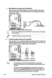
... this connector to this connector, set the item to the IEEE 1394a connector. By default, this connector, set the Front Panel Type item in the BIOS setup to [HD]. 2-34 Chapter 2: Hardware information Front panel audio connector (10-1 pin AAFP) This connector is for a chassis-mounted front panel audio I /O module cable...
... this connector to this connector, set the item to the IEEE 1394a connector. By default, this connector, set the Front Panel Type item in the BIOS setup to [HD]. 2-34 Chapter 2: Hardware information Front panel audio connector (10-1 pin AAFP) This connector is for a chassis-mounted front panel audio I /O module cable...
User Guide
Page 62
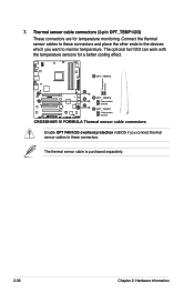
The optional fan1/2/3 can work with the temperature sensors for temperature monitoring. Enable OPT FAN1/2/3 overheat protection in BIOS if you connect thermal sensor cables to these connectors and place the other ends to the devices which you want to these connectors. Connect the thermal sensor cables to monitor temperature. The thermal sensor cable is purchased separately. 2-36 Chapter 2: Hardware information Thermal sensor cable connectors (2-pin OPT_TEMP1/2/3) These connectors are for a better cooling effect. 7.
The optional fan1/2/3 can work with the temperature sensors for temperature monitoring. Enable OPT FAN1/2/3 overheat protection in BIOS if you connect thermal sensor cables to these connectors and place the other ends to the devices which you want to these connectors. Connect the thermal sensor cables to monitor temperature. The thermal sensor cable is purchased separately. 2-36 Chapter 2: Hardware information Thermal sensor cable connectors (2-pin OPT_TEMP1/2/3) These connectors are for a better cooling effect. 7.
User Guide
Page 65
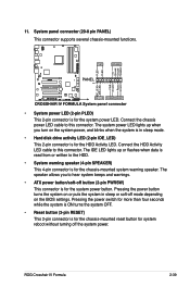
... is for the system power LED. The system power LED lights up or flashes when data is read from or written to this connector. ROG Crosshair IV Formula 2-39 System panel connector (20-8 pin PANEL) This connector supports several chassis-mounted functions. • System power LED (2-pin PLED) This 2-pin ... on the system power, and blinks when the system is in sleep or soft-off the system power. The speaker allows you turn on the BIOS settings. Connect the chassis power LED cable to hear system beeps and warnings. • ATX power button/soft-off button (2-pin PWRSW) This ...
... is for the system power LED. The system power LED lights up or flashes when data is read from or written to this connector. ROG Crosshair IV Formula 2-39 System panel connector (20-8 pin PANEL) This connector supports several chassis-mounted functions. • System power LED (2-pin PLED) This 2-pin ... on the system power, and blinks when the system is in sleep or soft-off the system power. The speaker allows you turn on the BIOS settings. Connect the chassis power LED cable to hear system beeps and warnings. • ATX power button/soft-off button (2-pin PWRSW) This ...
User Guide
Page 69
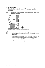
ROG Crosshair IV Formula 2-43 For ensuring the system performance, turn the switch setting to Enable when the system is powered off. • If you clear the CMOS or load the BIOS setup defaults, the related overclocking items in the BIOS menu follow the current setting of the Turbo Key II switch. • If you...to auto-tune your CPU to Enable under the OS environment, the Turbo Key II function will use the TurboV Auto Tuning, overclock in the BIOS setup program, and enable the Turbo Key II function at the same time. Turbo Key II switch This switch allows you change the switch setting...
ROG Crosshair IV Formula 2-43 For ensuring the system performance, turn the switch setting to Enable when the system is powered off. • If you clear the CMOS or load the BIOS setup defaults, the related overclocking items in the BIOS menu follow the current setting of the Turbo Key II switch. • If you...to auto-tune your CPU to Enable under the OS environment, the Turbo Key II function will use the TurboV Auto Tuning, overclock in the BIOS setup program, and enable the Turbo Key II function at the same time. Turbo Key II switch This switch allows you change the switch setting...
User Guide
Page 70
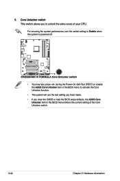
... setting to Enable when the system is powered off. • You may also press during the Power-On-Self-Test (POST) or enable the ASUS Core Unlocker item in the BIOS menu follows the current setting of your CPU. Core Unlocker switch This switch allows you clear the CMOS or load the... BIOS setup defaults, the ASUS Core Unlocker item in the BIOS menu to activate the Core Unlocker function. • The system will use the last setting you have made. • If you to...
... setting to Enable when the system is powered off. • You may also press during the Power-On-Self-Test (POST) or enable the ASUS Core Unlocker item in the BIOS menu follows the current setting of your CPU. Core Unlocker switch This switch allows you clear the CMOS or load the... BIOS setup defaults, the ASUS Core Unlocker item in the BIOS menu to activate the Core Unlocker function. • The system will use the last setting you have made. • If you to...
User Guide
Page 72
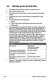
...the system chassis. 4. At power on self tests or POST. Connect the power cord to enter the BIOS Setup. Monitor b. While the tests are off. 3. If you do not see BIOS beep codes table below) or additional messages appear on the system front panel case lights up for assistance... with the last device on the devices in Chapter 3. 2-46 Chapter 2: Hardware information 2.9 Starting up . After making all switches are running, the BIOS beeps (see anything within 30 seconds from the time you press the ATX power button. For systems with "green" standards or if it has a ...
...the system chassis. 4. At power on self tests or POST. Connect the power cord to enter the BIOS Setup. Monitor b. While the tests are off. 3. If you do not see BIOS beep codes table below) or additional messages appear on the system front panel case lights up for assistance... with the last device on the devices in Chapter 3. 2-46 Chapter 2: Hardware information 2.9 Starting up . After making all switches are running, the BIOS beeps (see anything within 30 seconds from the time you press the ATX power button. For systems with "green" standards or if it has a ...
User Guide
Page 73
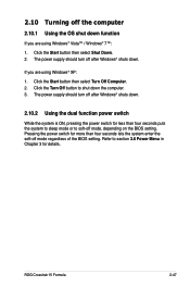
... 2.10.1 Using the OS shut down function If you are using Windows® XP: 1. The power supply should turn off mode, depending on the BIOS setting. ROG Crosshair IV Formula 2-47 The power supply should turn off after Windows® shuts down the computer. 3. Click the Start button then select Shut Down. 2. If...
... 2.10.1 Using the OS shut down function If you are using Windows® XP: 1. The power supply should turn off mode, depending on the BIOS setting. ROG Crosshair IV Formula 2-47 The power supply should turn off after Windows® shuts down the computer. 3. Click the Start button then select Shut Down. 2. If...
User Guide
Page 75
Detailed descriptions of the BIOS parameters are also provided. This chapter tells how to change the BIOS se3tup system settings through the BIOS Setup menus.
Detailed descriptions of the BIOS parameters are also provided. This chapter tells how to change the BIOS se3tup system settings through the BIOS Setup menus.


