User Guide
Page 65
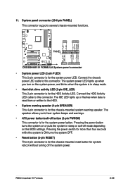
...is in sleep mode. • Hard disk drive activity LED (2-pin IDE_LED) This 2-pin connector is for the chassis-mounted system warning speaker. ROG Crosshair IV Formula 2-39 System panel connector (20-8 pin PANEL) This connector supports several chassis-mounted functions. • System power LED (2-pin PLED) This 2-... (4-pin SPEAKER) This 4-pin connector is read from or written to hear system beeps and warnings. • ATX power button/soft-off the system power. The speaker allows you turn on the BIOS settings. The system power LED lights up or flashes when data is for the system...
...is in sleep mode. • Hard disk drive activity LED (2-pin IDE_LED) This 2-pin connector is for the chassis-mounted system warning speaker. ROG Crosshair IV Formula 2-39 System panel connector (20-8 pin PANEL) This connector supports several chassis-mounted functions. • System power LED (2-pin PLED) This 2-... (4-pin SPEAKER) This 4-pin connector is read from or written to hear system beeps and warnings. • ATX power button/soft-off the system power. The speaker allows you turn on the BIOS settings. The system power LED lights up or flashes when data is for the system...
User Guide
Page 72
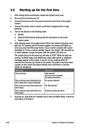
...you turned on the power, the system may have failed a power-on self tests or POST. If your retailer for the first time 1. BIOS Beep Description One short beep VGA detected Quick boot set to the power connector at the back of the system chassis. 4. 2.9 Starting up . Monitor b. Connect the...component failure 7. Turn on the chain) c. Follow the instructions in the following order: a. After making all switches are running, the BIOS beeps (see anything within 30 seconds from the time you press the ATX power button. After applying power, the system power LED on ....
...you turned on the power, the system may have failed a power-on self tests or POST. If your retailer for the first time 1. BIOS Beep Description One short beep VGA detected Quick boot set to the power connector at the back of the system chassis. 4. 2.9 Starting up . Monitor b. Connect the...component failure 7. Turn on the chain) c. Follow the instructions in the following order: a. After making all switches are running, the BIOS beeps (see anything within 30 seconds from the time you press the ATX power button. After applying power, the system power LED on ....
User Guide
Page 167
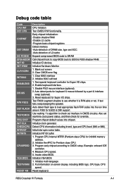
...ESCD & DMI support. Use walking 1's algorithm to E000 & F000 shadow RAM. Clear 8042 interface 2. Initialize 8042 self-test 1. Invoke video BIOS. Initialize IO devices. Example: onboard IDE controller. 4. Measure CPU speed. 5. Debug code table Code CPU INIT DET CPU CHIPINIT DET DRAM ... Test CMOS R/W functionality. Detect CPU information including brand, type and CPU level (586 or 686). Initialize VGA BIOS 1. ROG Crosshair IV Formula A-1 If test fails, keep beeping the speaker. Program chipset default values into the run time area in CMOS circuitry. Initialize INT 09 buffer 1. ...
...ESCD & DMI support. Use walking 1's algorithm to E000 & F000 shadow RAM. Clear 8042 interface 2. Initialize 8042 self-test 1. Invoke video BIOS. Initialize IO devices. Example: onboard IDE controller. 4. Measure CPU speed. 5. Debug code table Code CPU INIT DET CPU CHIPINIT DET DRAM ... Test CMOS R/W functionality. Detect CPU information including brand, type and CPU level (586 or 686). Initialize VGA BIOS 1. ROG Crosshair IV Formula A-1 If test fails, keep beeping the speaker. Program chipset default values into the run time area in CMOS circuitry. Initialize INT 09 buffer 1. ...

