
AT5IONT-I User's manual
Page 1
Motherboard AT5IONT-I DELUXE AT5IONT-I
Motherboard AT5IONT-I DELUXE AT5IONT-I
AT5IONT-I User's manual
Page 9
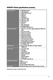
...1 x SATA power connector* 1 x System panel connector 1 x Front panel audio connector 1 x Internal speaker connector 1 x 24-pin EATX power connector** * For AT5IONT-I DELUXE only ** For AT5IONT-I only 8 Mb Flash ROM, AMI BIOS, PnP, DMI2.0, WfM2.0, SMBIOS 2.5 2 x Serial ATA cables 1 x I/O shield 1 x User Manual 1 x SATA... Power cable* 1 x Remote Controller* 1 x Receiver* 1 x 90W DC adapter* 1 x Power cord* * For AT5IONT-I DELUXE only Drivers ASUS PC Probe II ASUS Update Anti-virus software (OEM version) Mini ITX form factor: 6.75 in x 6.75 in (17.1cm x 17.1cm) *Specifications are ...
...1 x SATA power connector* 1 x System panel connector 1 x Front panel audio connector 1 x Internal speaker connector 1 x 24-pin EATX power connector** * For AT5IONT-I DELUXE only ** For AT5IONT-I only 8 Mb Flash ROM, AMI BIOS, PnP, DMI2.0, WfM2.0, SMBIOS 2.5 2 x Serial ATA cables 1 x I/O shield 1 x User Manual 1 x SATA... Power cable* 1 x Remote Controller* 1 x Receiver* 1 x 90W DC adapter* 1 x Power cord* * For AT5IONT-I DELUXE only Drivers ASUS PC Probe II ASUS Update Anti-virus software (OEM version) Mini ITX form factor: 6.75 in x 6.75 in (17.1cm x 17.1cm) *Specifications are ...
AT5IONT-I User's manual
Page 10
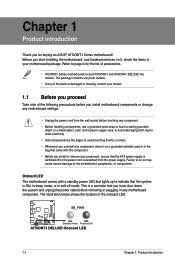
... to do so may cause severe damage to page ix for buying an ASUS® AT5IONT-I Series motherboard! SB_PWR AT5IONT-I DELUXE ON OFF Standby Power Powered Off AT5IONT-I DELUXE two models. The package contents vary from the power supply. Before you start...to the motherboard, peripherals, or components. Chapter 1 Product introduction Thank you for the list of accessories. • AT5IONT-I Series motherboards include AT5IONT-I and AT5IONT-I DELUXE Onboard LED 1-1 Chapter 1: Product introduction Onboard LED The motherboard comes with the component. • Before you install...
... to do so may cause severe damage to page ix for buying an ASUS® AT5IONT-I Series motherboard! SB_PWR AT5IONT-I DELUXE ON OFF Standby Power Powered Off AT5IONT-I DELUXE two models. The package contents vary from the power supply. Before you start...to the motherboard, peripherals, or components. Chapter 1 Product introduction Thank you for the list of accessories. • AT5IONT-I Series motherboards include AT5IONT-I and AT5IONT-I DELUXE Onboard LED 1-1 Chapter 1: Product introduction Onboard LED The motherboard comes with the component. • Before you install...
AT5IONT-I User's manual
Page 11
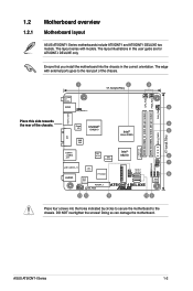
... USBPW56 LAN1_USB3.0_12 NEC USB3.0 AUDIO ALC 887 P17C9X20 USB56 SATA1 SATA2 CLRTC 8 8Mb BIOS AAFP PCIEX4_1 SB_PWR AT5IONT-I DELUXE only. The layout illustrations in the correct orientation. Doing so can damage the motherboard. ASUS AT5IONT-I DELUXE two models. The edge with models. Ensure that you install the motherboard into the holes indicated by circles...
... USBPW56 LAN1_USB3.0_12 NEC USB3.0 AUDIO ALC 887 P17C9X20 USB56 SATA1 SATA2 CLRTC 8 8Mb BIOS AAFP PCIEX4_1 SB_PWR AT5IONT-I DELUXE only. The layout illustrations in the correct orientation. Doing so can damage the motherboard. ASUS AT5IONT-I DELUXE two models. The edge with models. Ensure that you install the motherboard into the holes indicated by circles...
AT5IONT-I User's manual
Page 12
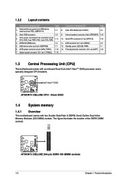
... Outline Dual Inline Memory Modules (SO-DIMM) sockets. The figure illustrates the location of the DDR3 DIMM sockets: DIMM_A1 DIMM_A2 AT5IONT-I DELUXE AT5IONT-I DELUXE CPU - DDR3 SO-DIMM slots 1-3 11. Atom D525 processor 1-3 9. D525 AT5IONT-I DELUXE AT5IONT-I DELUXE 204-pin DDR3 SO-DIMM sockets 1-3 Chapter 1: Product introduction CPU, power, and chassis fan connectors (3-pin CPU_FAN, 3-pin PWR_FAN, 3-pin...
... Outline Dual Inline Memory Modules (SO-DIMM) sockets. The figure illustrates the location of the DDR3 DIMM sockets: DIMM_A1 DIMM_A2 AT5IONT-I DELUXE AT5IONT-I DELUXE CPU - DDR3 SO-DIMM slots 1-3 11. Atom D525 processor 1-3 9. D525 AT5IONT-I DELUXE AT5IONT-I DELUXE 204-pin DDR3 SO-DIMM sockets 1-3 Chapter 1: Product introduction CPU, power, and chassis fan connectors (3-pin CPU_FAN, 3-pin PWR_FAN, 3-pin...
AT5IONT-I User's manual
Page 15
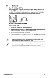
... ON the computer. 4. Removing the cap will cause system boot failure! CLRTC 12 23 AT5IONT-I DELUXE Normal (Default) Clear RTC AT5IONT-I Series 1-6 If the steps above do not help, remove the onboard battery and move the cap back to pins 2-3. ASUS AT5IONT-I DELUXE Clear RTC RAM To erase the RTC RAM: 1. After clearing the CMOS, reinstall...
... ON the computer. 4. Removing the cap will cause system boot failure! CLRTC 12 23 AT5IONT-I DELUXE Normal (Default) Clear RTC AT5IONT-I Series 1-6 If the steps above do not help, remove the onboard battery and move the cap back to pins 2-3. ASUS AT5IONT-I DELUXE Clear RTC RAM To erase the RTC RAM: 1. After clearing the CMOS, reinstall...
AT5IONT-I User's manual
Page 16
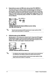
...sleep mode. 1-7 Chapter 1: Product introduction otherwise, the system would not power up feature. PS2_USBPW1-4 12 23 +5V +5VSB (Default) AT5IONT-I DELUXE AT5IONT-I DELUXE USB Device Wake-up • The USB device wake-up feature requires a power supply that can wake up The total current consumed must ... whether under normal condition or in the BIOS. The USBPW1-4 jumper is for each USB port; USBPW56 12 23 AT5IONT-I DELUXE +5V (Default) +5VSB AT5IONT-I DELUXE PS2 Keyboard/Mouse power setting and USB device wake-up the computer by pressing a key on the +5VSB lead for...
...sleep mode. 1-7 Chapter 1: Product introduction otherwise, the system would not power up feature. PS2_USBPW1-4 12 23 +5V +5VSB (Default) AT5IONT-I DELUXE AT5IONT-I DELUXE USB Device Wake-up • The USB device wake-up feature requires a power supply that can wake up The total current consumed must ... whether under normal condition or in the BIOS. The USBPW1-4 jumper is for each USB port; USBPW56 12 23 AT5IONT-I DELUXE +5V (Default) +5VSB AT5IONT-I DELUXE PS2 Keyboard/Mouse power setting and USB device wake-up the computer by pressing a key on the +5VSB lead for...
AT5IONT-I User's manual
Page 17
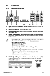
... SPEED LED Status OFF ORANGE GREEN Description 10 Mbps connection 100 Mbps connection 1 Gbps connection ACT/LINK SPEED LED LED LAN port ASUS AT5IONT-I DELUXE only). 1.7 Connectors 1.7.1 Rear panel connectors 1 2 3 4 5 67 15 14 13 12 11 10 9 8 1. This...Support DVD's Drivers screen, follow the steps below for AT5IONT-I DELUXE only). This port connects to achieve the complete Bluetooth functions, download the latest Bluetooth driver from the ASUS support wedsite at http://support.asus.com. • Bluetooth Electrical Specification: Bluetooth specification V.2.1...
... SPEED LED Status OFF ORANGE GREEN Description 10 Mbps connection 100 Mbps connection 1 Gbps connection ACT/LINK SPEED LED LED LAN port ASUS AT5IONT-I DELUXE only). 1.7 Connectors 1.7.1 Rear panel connectors 1 2 3 4 5 67 15 14 13 12 11 10 9 8 1. This...Support DVD's Drivers screen, follow the steps below for AT5IONT-I DELUXE only). This port connects to achieve the complete Bluetooth functions, download the latest Bluetooth driver from the ASUS support wedsite at http://support.asus.com. • Bluetooth Electrical Specification: Bluetooth specification V.2.1...
AT5IONT-I User's manual
Page 18
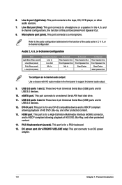
Line Out port (lime). This port connects to a headphone or a speaker. Refer to the audio configuration table below for AT5IONT-I DELUXE only). eSATA port. DVI-D port. This port connects to a microphone. Audio 2, 4, 6, or 8-channel configuration Port Light Blue (Rear panel) Lime (Rear panel) Pink (Rear panel) ...
Line Out port (lime). This port connects to a headphone or a speaker. Refer to the audio configuration table below for AT5IONT-I DELUXE only). eSATA port. DVI-D port. This port connects to a microphone. Audio 2, 4, 6, or 8-channel configuration Port Light Blue (Rear panel) Lime (Rear panel) Pink (Rear panel) ...
AT5IONT-I User's manual
Page 19
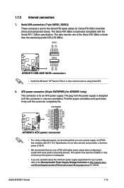
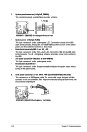
...AT5IONT-I DELUXE AT5IONT-I only) This connector is for an ATX power supply. ATX power connector (24-pin EATXPWR) (for your system, refer to fit this connector in only one orientation. The system may become unstable or may not boot up if the power is faster than the standard parallel ATA (133 MB/s). ASUS AT5IONT...disk drives. Serial ATA connectors (7-pin SATA1, SATA2) These connectors are uncertain about the minimum power supply requirement for AT5IONT-I DELUXE SATA connectors • Install the Windows® XP Service Pack 2 or later versions before using Serial ATA. 2....
...AT5IONT-I DELUXE AT5IONT-I only) This connector is for an ATX power supply. ATX power connector (24-pin EATXPWR) (for your system, refer to fit this connector in only one orientation. The system may become unstable or may not boot up if the power is faster than the standard parallel ATA (133 MB/s). ASUS AT5IONT...disk drives. Serial ATA connectors (7-pin SATA1, SATA2) These connectors are uncertain about the minimum power supply requirement for AT5IONT-I DELUXE SATA connectors • Install the Windows® XP Service Pack 2 or later versions before using Serial ATA. 2....
AT5IONT-I User's manual
Page 20
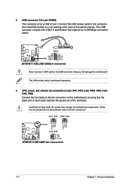
... fan connectors on the fan connectors! CPU_FAN PWR_FAN Rotation +12V GND Rotation +12V GND CHA_FAN AT5IONT-I DELUXE GND +12V Rotation AT5IONT-I DELUXE USB2.0 connector Never connect a 1394 cable to a slot opening at the back of the connector. USB56 AT5IONT-I DELUXE PIN 1 AT5IONT-I DELUXE fan connectors 1-11 Chapter 1: Product introduction Doing so will damage the motherboard! Connect the USB...
... fan connectors on the fan connectors! CPU_FAN PWR_FAN Rotation +12V GND Rotation +12V GND CHA_FAN AT5IONT-I DELUXE GND +12V Rotation AT5IONT-I DELUXE USB2.0 connector Never connect a 1394 cable to a slot opening at the back of the connector. USB56 AT5IONT-I DELUXE PIN 1 AT5IONT-I DELUXE fan connectors 1-11 Chapter 1: Product introduction Doing so will damage the motherboard! Connect the USB...
AT5IONT-I User's manual
Page 21
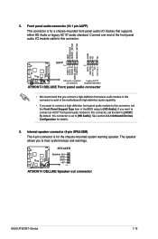
..., this connector. Internal speaker connector (4-pin SPEAKER) The 4-pin connector is for a chassis-mounted front panel audio I Series 1-12 SPEAKER AT5IONT-I DELUXE Speaker Out GND GND +5V PIN 1 AT5IONT-I DELUXE Speaker out connector ASUS AT5IONT-I /O module that you connect a high-definition front panel audio module to this connector to avail of the motherboard's high-definition audio...
..., this connector. Internal speaker connector (4-pin SPEAKER) The 4-pin connector is for a chassis-mounted front panel audio I Series 1-12 SPEAKER AT5IONT-I DELUXE Speaker Out GND GND +5V PIN 1 AT5IONT-I DELUXE Speaker out connector ASUS AT5IONT-I /O module that you connect a high-definition front panel audio module to this connector to avail of the motherboard's high-definition audio...
AT5IONT-I User's manual
Page 22
...orientation. The power cable plug is for the HDD Activity LED. Connect the chassis power LED cable to this connector. AT5IONT-I DELUXE AT5IONT-I DELUXE only) This connectors is for the chassis-mounted reset button for SATA power cable. System panel connector (10-1 pin ... This connector supports several chassis-mounted functions. F_PANEL PWR LED PWR BTN PIN 1 HD_LED RESET GND PWR PLEDPLED+ Reset Ground IDE_LEDIDE_LED+ AT5IONT-I DELUXE AT5IONT-I DELUXE System panel connector • System power LED (2-pin PLED) This 2-pin connector is designed to the HDD. • ATX power...
...orientation. The power cable plug is for the HDD Activity LED. Connect the chassis power LED cable to this connector. AT5IONT-I DELUXE AT5IONT-I DELUXE only) This connectors is for the chassis-mounted reset button for SATA power cable. System panel connector (10-1 pin ... This connector supports several chassis-mounted functions. F_PANEL PWR LED PWR BTN PIN 1 HD_LED RESET GND PWR PLEDPLED+ Reset Ground IDE_LEDIDE_LED+ AT5IONT-I DELUXE AT5IONT-I DELUXE System panel connector • System power LED (2-pin PLED) This 2-pin connector is designed to the HDD. • ATX power...
AT5IONT-I User's manual
Page 28
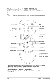
Using the remote controller (for AT5IONT-I DELUXE only) Use the remote controller to 7 before using the remote controller. The Tranquil mode button is fanless-designed. Connect the IR receiver to the USB 2.0 ... 2 before using the Internet Radio. *** Set the Favorite Music in Windows® Control Panel > Power Options. ** Set up the Internet radio channel 1 to launch the ASUS Home Theater Gate and start media applications. Power on/off* Fast rewind Stop Previous track Volume up OK Scroll left Main window Switch windows Internet...
Using the remote controller (for AT5IONT-I DELUXE only) Use the remote controller to 7 before using the remote controller. The Tranquil mode button is fanless-designed. Connect the IR receiver to the USB 2.0 ... 2 before using the Internet Radio. *** Set the Favorite Music in Windows® Control Panel > Power Options. ** Set up the Internet radio channel 1 to launch the ASUS Home Theater Gate and start media applications. Power on/off* Fast rewind Stop Previous track Volume up OK Scroll left Main window Switch windows Internet...
AT5IONT-I User's manual
Page 32
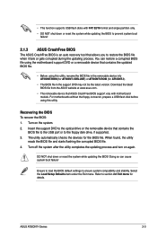
... the removable device into AT5IONT.ROM (for AT5IONT-I DELUXE) or AT5IONTI.ROM (for AT5IONT-I Series 2-3 Refer to the optical drive or the removable device that ASUS CrashFree BIOS support vary with FAT 32/16 format and single partition only. • DO NOT shut down or reset the system while updating the BIOS! ASUS AT5IONT-I ). • The BIOS...
... the removable device into AT5IONT.ROM (for AT5IONT-I DELUXE) or AT5IONTI.ROM (for AT5IONT-I Series 2-3 Refer to the optical drive or the removable device that ASUS CrashFree BIOS support vary with FAT 32/16 format and single partition only. • DO NOT shut down or reset the system while updating the BIOS! ASUS AT5IONT-I ). • The BIOS...
AT5IONT-I User's manual
Page 33
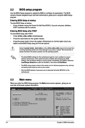
... motherboard. 2.3 Main menu When you enter the BIOS Setup program, the Main menu screen appears, giving you failed to your screen. • Visit the ASUS website at startup: • Press during the Power-On Self Test (POST). Select the Load Setups Default item under the Exit Menu. 2.2 BIOS setup ...program Use the BIOS Setup program to select a field. If you see on your data or system. Main Advanced AT5IONT-I DELUXE BIOS Setup Power Boot Tools Exit Version 0214 System Time [00:31:48] System Date [Tue 01/01/2002] Use [ENTER], [TAB] or [SHIFT...
... motherboard. 2.3 Main menu When you enter the BIOS Setup program, the Main menu screen appears, giving you failed to your screen. • Visit the ASUS website at startup: • Press during the Power-On Self Test (POST). Select the Load Setups Default item under the Exit Menu. 2.2 BIOS setup ...program Use the BIOS Setup program to select a field. If you see on your data or system. Main Advanced AT5IONT-I DELUXE BIOS Setup Power Boot Tools Exit Version 0214 System Time [00:31:48] System Date [Tue 01/01/2002] Use [ENTER], [TAB] or [SHIFT...
AT5IONT-I User's manual
Page 36
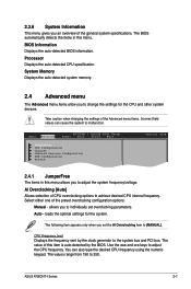
...when changing the settings of this item is auto-detected by the clock generator to the system bus and PCI bus. ASUS AT5IONT-I DELUXE BIOS Setup Power Boot Tools Exit JumperFree CPU Configuration Chipset Onboard Devices Configuration USB Configuration PCIPnP Version 0214 2.4.1 JumperFree The ...value of the Advanced menu items. Incorrect field values can also type the desired CPU frequency using the numeric keypad. Main Advanced AT5IONT-I Series 2-7 2.3.6 System Information This menu gives you to change the settings for the system. loads the optimal settings for the...
...when changing the settings of this item is auto-detected by the clock generator to the system bus and PCI bus. ASUS AT5IONT-I DELUXE BIOS Setup Power Boot Tools Exit JumperFree CPU Configuration Chipset Onboard Devices Configuration USB Configuration PCIPnP Version 0214 2.4.1 JumperFree The ...value of the Advanced menu items. Incorrect field values can also type the desired CPU frequency using the numeric keypad. Main Advanced AT5IONT-I Series 2-7 2.3.6 System Information This menu gives you to change the settings for the system. loads the optimal settings for the...
AT5IONT-I User's manual
Page 38
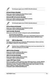
...Enabled] Allows you to select the front panel support type. Configuration options: [Disabled] [Enabled] [Auto] ASUS AT5IONT-I DELUXE motherboard. The following item appears only on AT5IONT-I Series 2-9 Onboard Bluetooth [Enabled] Allows you to display the configuration options. Configuration options: [Enabled] [... USB flash drives and USB hard drives. Configuration options: [Enabled] [Disabled] The following item appears only on AT5IONT-I DELUXE motherboard. If no USB device is disabled. Onboard Wireless [Enabled] Allows you to enable or disable the onboard ...
...Enabled] Allows you to select the front panel support type. Configuration options: [Disabled] [Enabled] [Auto] ASUS AT5IONT-I DELUXE motherboard. The following item appears only on AT5IONT-I Series 2-9 Onboard Bluetooth [Enabled] Allows you to display the configuration options. Configuration options: [Enabled] [... USB flash drives and USB hard drives. Configuration options: [Enabled] [Disabled] The following item appears only on AT5IONT-I DELUXE motherboard. If no USB device is disabled. Onboard Wireless [Enabled] Allows you to enable or disable the onboard ...
AT5IONT-I User's manual
Page 40
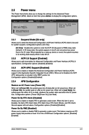
.... Configuration options: [Disabled] [Enabled] Power On By PME [Disabled] Allows you to enable or disable PME to RAM) sleep state (default). Configuration options: [Disabled] [Enabled] ASUS AT5IONT-I DELUXE BIOS Setup Power Boot Tools Exit Suspend Mode [S3 only] ACPI 2.0 Support [Enabled] ACPI APIC Support [Enabled] APM Configuration Hardware Monitor Version 0214 Select the... allow you to Enabled, the items RTC Alarm Date, RTC Alarm Hour, RTC Alarm Minute, and RTC Alarm Second appear with set values. Main Advanced AT5IONT-I Series 2-11
.... Configuration options: [Disabled] [Enabled] Power On By PME [Disabled] Allows you to enable or disable PME to RAM) sleep state (default). Configuration options: [Disabled] [Enabled] ASUS AT5IONT-I DELUXE BIOS Setup Power Boot Tools Exit Suspend Mode [S3 only] ACPI 2.0 Support [Enabled] ACPI APIC Support [Enabled] APM Configuration Hardware Monitor Version 0214 Select the... allow you to Enabled, the items RTC Alarm Date, RTC Alarm Hour, RTC Alarm Minute, and RTC Alarm Second appear with set values. Main Advanced AT5IONT-I Series 2-11
AT5IONT-I User's manual
Page 41
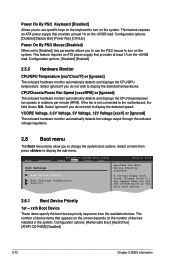
.... If the fan is not connected to turn on the system. Select Ignored if you do not wish to display the sub-menu. Main Advanced AT5IONT-I DELUXE BIOS Setup Power Boot Tools Exit Boot Settings Boot Device Priority Boot Settings Configuration Security Version 0214 Specifies the Boot Device Priority sequence. This feature...
.... If the fan is not connected to turn on the system. Select Ignored if you do not wish to display the sub-menu. Main Advanced AT5IONT-I DELUXE BIOS Setup Power Boot Tools Exit Boot Settings Boot Device Priority Boot Settings Configuration Security Version 0214 Specifies the Boot Device Priority sequence. This feature...


