AT5IONT-I User's manual
Page 1
Motherboard AT5IONT-I DELUXE AT5IONT-I
Motherboard AT5IONT-I DELUXE AT5IONT-I
AT5IONT-I User's manual
Page 3
Contents Notices...v Safety information vi About this guide vi AT5IONT-I Series specifications summary viii Chapter 1: Product introduction 1.1 Before you proceed 1-1 1.2 Motherboard overview 1-2 1.2.1 Motherboard layout 1-2 1.2.2 Layout contents 1-3 1.3 Central Processing Unit (CPU 1-3 1.4 System memory 1-3 1.4.1 Overview 1-3 1.4.2... Software support 1-14 1.8.1 Installing an operating system 1-14 1.8.2 Support DVD information 1-14 1.8.3 ASUS VideoSecurity 1-15 1.8.4 ASUS Home Theater Gate 1-17 1.8.5 ASUS @Vibe 1-20 Chapter 2: BIOS information 2.1 Managing and updating your BIOS...
Contents Notices...v Safety information vi About this guide vi AT5IONT-I Series specifications summary viii Chapter 1: Product introduction 1.1 Before you proceed 1-1 1.2 Motherboard overview 1-2 1.2.1 Motherboard layout 1-2 1.2.2 Layout contents 1-3 1.3 Central Processing Unit (CPU 1-3 1.4 System memory 1-3 1.4.1 Overview 1-3 1.4.2... Software support 1-14 1.8.1 Installing an operating system 1-14 1.8.2 Support DVD information 1-14 1.8.3 ASUS VideoSecurity 1-15 1.8.4 ASUS Home Theater Gate 1-17 1.8.5 ASUS @Vibe 1-20 Chapter 2: BIOS information 2.1 Managing and updating your BIOS...
AT5IONT-I User's manual
Page 5
...and Restriction of the crossed out wheeled bin indicates that the battery should not be placed in municipal waste. DO NOT throw the motherboard in municipal waste. Changes or modifications to this unit not expressly approved by the party responsible for help. This symbol of Chemicals)...These limits are designed to which the receiver is no guarantee that interference will not occur in our products at ASUS REACH website at http://csr.asus.com/english/REACH.htm. Notices Federal Communications Commission Statement This device complies with Part 15 of electronic products. This ...
...and Restriction of the crossed out wheeled bin indicates that the battery should not be placed in municipal waste. DO NOT throw the motherboard in municipal waste. Changes or modifications to this unit not expressly approved by the party responsible for help. This symbol of Chemicals)...These limits are designed to which the receiver is no guarantee that interference will not occur in our products at ASUS REACH website at http://csr.asus.com/english/REACH.htm. Notices Federal Communications Commission Statement This device complies with Part 15 of electronic products. This ...
AT5IONT-I User's manual
Page 6
... How this guide This user guide contains the information you add a device. • Before connecting or removing signal cables from the motherboard, ensure that all power cables are unplugged. • Seek professional assistance before using the product, ensure that all cables are correctly connected...the grounding circuit. • Ensure that the power cables for the devices are unplugged before you need when installing and configuring the motherboard. If you are connected. Do not place the product in your power supply is organized This guide contains the following parts: &#...
... How this guide This user guide contains the information you add a device. • Before connecting or removing signal cables from the motherboard, ensure that all power cables are unplugged. • Seek professional assistance before using the product, ensure that all cables are correctly connected...the grounding circuit. • Ensure that the power cables for the devices are unplugged before you need when installing and configuring the motherboard. If you are connected. Do not place the product in your power supply is organized This guide contains the following parts: &#...
AT5IONT-I User's manual
Page 10
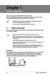
... may cause severe damage to page ix for buying an ASUS® AT5IONT-I Series motherboard! The illustration below shows the location of accessories. • AT5IONT-I Series motherboards include AT5IONT-I and AT5IONT-I DELUXE Onboard LED 1-1 Chapter 1: Product introduction Chapter 1 Product introduction Thank you install motherboard components or change any motherboard settings. • Unplug the power cord from the power supply...
... may cause severe damage to page ix for buying an ASUS® AT5IONT-I Series motherboard! The illustration below shows the location of accessories. • AT5IONT-I Series motherboards include AT5IONT-I and AT5IONT-I DELUXE Onboard LED 1-1 Chapter 1: Product introduction Chapter 1 Product introduction Thank you install motherboard components or change any motherboard settings. • Unplug the power cord from the power supply...
AT5IONT-I User's manual
Page 11
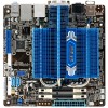
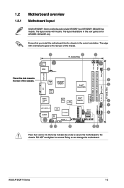
... 12 11 10 9 Place four screws into the chassis in this side towards the rear of the chassis. 1.2 1.2.1 Motherboard overview Motherboard layout ASUS AT5IONT-I Series motherboards include AT5IONT-I and AT5IONT-I Series 1-2 The edge with models. Doing so can damage the motherboard. The layout illustrations in the correct orientation. Super NVIDIA® 4 I/O ION2010 Intel® 5 Atom D525 DVI JMB...
... 12 11 10 9 Place four screws into the chassis in this side towards the rear of the chassis. 1.2 1.2.1 Motherboard overview Motherboard layout ASUS AT5IONT-I Series motherboards include AT5IONT-I and AT5IONT-I Series 1-2 The edge with models. Doing so can damage the motherboard. The layout illustrations in the correct orientation. Super NVIDIA® 4 I/O ION2010 Intel® 5 Atom D525 DVI JMB...
AT5IONT-I User's manual
Page 12
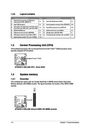
..., power, and chassis fan connectors (3-pin CPU_FAN, 3-pin PWR_FAN, 3-pin CHA_FAN) 1-11 10. Atom D525 1.4 System memory 1.4.1 Overview This motherboard comes with an onboard Dual-Core Intel® Atom™ D525 processor and a specially designed CPU heatsink. Standby power LED (SB_PWR) 1-1 6. ...) sockets. Serial ATA connectors (7-pin SATA1/2) 1-10 4. The figure illustrates the location of the DDR3 DIMM sockets: DIMM_A1 DIMM_A2 AT5IONT-I DELUXE AT5IONT-I DELUXE CPU - Keyboard/mouse power and USB device wake-up (3-pin USBPW56) 1-7 12. SATA power connector (4-pin SATA_PWR1) ...
..., power, and chassis fan connectors (3-pin CPU_FAN, 3-pin PWR_FAN, 3-pin CHA_FAN) 1-11 10. Atom D525 1.4 System memory 1.4.1 Overview This motherboard comes with an onboard Dual-Core Intel® Atom™ D525 processor and a specially designed CPU heatsink. Standby power LED (SB_PWR) 1-1 6. ...) sockets. Serial ATA connectors (7-pin SATA1/2) 1-10 4. The figure illustrates the location of the DDR3 DIMM sockets: DIMM_A1 DIMM_A2 AT5IONT-I DELUXE AT5IONT-I DELUXE CPU - Keyboard/mouse power and USB device wake-up (3-pin USBPW56) 1-7 12. SATA power connector (4-pin SATA_PWR1) ...
AT5IONT-I User's manual
Page 13
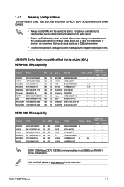
... 1GB DIMM PC3-8500 1GB KINGTIGER 1GB DIMM PC3-8500 1GB SS/ Chip DS Brand Chip NO. Visit the ASUS website at 800MHz on the motherboard, the actual usable memory for the latest QVL. Size SS/DS Chip Brand APACER AS01GFA33C9NBGC 1GB DS HYNIX HMT112S6TFR8C-... ELPIDA ELPIDA Chip NO. D1288JELDPGD9U - - For optimum compatibility, it is recommended that you install 4GB or more memory on AT5IONT-I Series motherboards. Timing Voltage AM5D5808AEWSBG 9 - ASUS AT5IONT-I Series Motherboard Qualified Vendors Lists (QVL) DDR3-1067 MHz capability Vendors Part No.
... 1GB DIMM PC3-8500 1GB KINGTIGER 1GB DIMM PC3-8500 1GB SS/ Chip DS Brand Chip NO. Visit the ASUS website at 800MHz on the motherboard, the actual usable memory for the latest QVL. Size SS/DS Chip Brand APACER AS01GFA33C9NBGC 1GB DS HYNIX HMT112S6TFR8C-... ELPIDA ELPIDA Chip NO. D1288JELDPGD9U - - For optimum compatibility, it is recommended that you install 4GB or more memory on AT5IONT-I Series motherboards. Timing Voltage AM5D5808AEWSBG 9 - ASUS AT5IONT-I Series Motherboard Qualified Vendors Lists (QVL) DDR3-1067 MHz capability Vendors Part No.
AT5IONT-I User's manual
Page 14
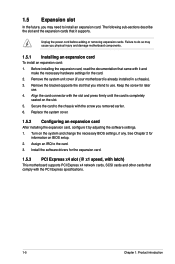
...following sub‑sections describe the slot and the expansion cards that came with latch) This motherboard supports PCI Express x4 network cards, SCSI cards and other cards that you physical injury and damage motherboard components. 1.5.1 Installing an expansion card To install an expansion card: 1. Keep the screw .... 1-5 Chapter 1: Product introduction Install the software drivers for information on the slot. 5. Remove the system unit cover (if your motherboard is completely seated on BIOS setup. 2. Turn on the system and change the necessary BIOS settings, if any.
...following sub‑sections describe the slot and the expansion cards that came with latch) This motherboard supports PCI Express x4 network cards, SCSI cards and other cards that you physical injury and damage motherboard components. 1.5.1 Installing an expansion card To install an expansion card: 1. Keep the screw .... 1-5 Chapter 1: Product introduction Install the software drivers for information on the slot. 5. Remove the system unit cover (if your motherboard is completely seated on BIOS setup. 2. Turn on the system and change the necessary BIOS settings, if any.
AT5IONT-I User's manual
Page 20
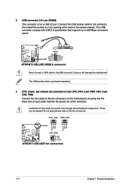
... cable to this connector, then install the module to the USB connector. Doing so will damage the motherboard! These are not jumpers! CPU_FAN PWR_FAN Rotation +12V GND Rotation +12V GND CHA_FAN AT5IONT-I DELUXE GND +12V Rotation AT5IONT-I DELUXE USB2.0 connector Never connect a 1394 cable to a slot opening at the back of the connector...
... cable to this connector, then install the module to the USB connector. Doing so will damage the motherboard! These are not jumpers! CPU_FAN PWR_FAN Rotation +12V GND Rotation +12V GND CHA_FAN AT5IONT-I DELUXE GND +12V Rotation AT5IONT-I DELUXE USB2.0 connector Never connect a 1394 cable to a slot opening at the back of the connector...
AT5IONT-I User's manual
Page 21
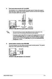
... to avail of the front panel audio I/O module cable to this connector is for details. 6. SPEAKER AT5IONT-I DELUXE Speaker Out GND GND +5V PIN 1 AT5IONT-I DELUXE Speaker out connector ASUS AT5IONT-I DELUXE Front panel audio connector • We recommend that supports either HD Audio or legacy AC`97 audio... audio module to this connector, set the Front Panel Support Type item in the BIOS setup to [AC97]. Connect one end of the motherboard's high-definition audio capability. • If you want to connect a high-definition front panel audio module to this connector, set to...
... to avail of the front panel audio I/O module cable to this connector is for details. 6. SPEAKER AT5IONT-I DELUXE Speaker Out GND GND +5V PIN 1 AT5IONT-I DELUXE Speaker out connector ASUS AT5IONT-I DELUXE Front panel audio connector • We recommend that supports either HD Audio or legacy AC`97 audio... audio module to this connector, set the Front Panel Support Type item in the BIOS setup to [AC97]. Connect one end of the motherboard's high-definition audio capability. • If you want to connect a high-definition front panel audio module to this connector, set to...
AT5IONT-I User's manual
Page 23
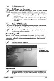
...the Support DVD Place the Support DVD to maximize the features of ASUS motherboard. ASUS AT5IONT-I Series 1-14 Visit the ASUS website at any time without notice. 1.8 Software support 1.8.1 Installing an operating system This motherboard supports Windows® XP/Vista/7 Operating Systems (OS). The contents... of the Support DVD to change at www.asus.com for updates. The following screen is enabled in your computer,...
...the Support DVD Place the Support DVD to maximize the features of ASUS motherboard. ASUS AT5IONT-I Series 1-14 Visit the ASUS website at any time without notice. 1.8 Software support 1.8.1 Installing an operating system This motherboard supports Windows® XP/Vista/7 Operating Systems (OS). The contents... of the Support DVD to change at www.asus.com for updates. The following screen is enabled in your computer,...
AT5IONT-I User's manual
Page 24
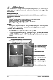
... harwares installed on their properties from a remote location via the Internet and a wide range of video capturing devices. To launch the ASUS VideoSecurity from the motherboard support DVD. 2. Launching ASUS VideoSecurity 1. ASUS VideoSecurity main screen Click to close VodeoSecurity Click to minimize the main window Click to open the Help file Click to open...
... harwares installed on their properties from a remote location via the Internet and a wide range of video capturing devices. To launch the ASUS VideoSecurity from the motherboard support DVD. 2. Launching ASUS VideoSecurity 1. ASUS VideoSecurity main screen Click to close VodeoSecurity Click to minimize the main window Click to open the Help file Click to open...
AT5IONT-I User's manual
Page 26
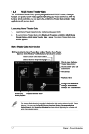
... and movies. Install Home Theater Gate from the motherboard support DVD. 2. Click the Home Theater Gate icon in the bundled trial version software "mediaU Player Mercury". 1.8.4 ASUS Home Theater Gate The ASUS Home Theater Gate, specially designed for the AT5IONT-I series, allows you can launch the ASUS Home Theater Gate and start media applications with...
... and movies. Install Home Theater Gate from the motherboard support DVD. 2. Click the Home Theater Gate icon in the bundled trial version software "mediaU Player Mercury". 1.8.4 ASUS Home Theater Gate The ASUS Home Theater Gate, specially designed for the AT5IONT-I series, allows you can launch the ASUS Home Theater Gate and start media applications with...
AT5IONT-I User's manual
Page 28
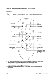
... window Switch windows Internet Radio** Music*** Mute Play/Pause Fast forward Next track Volume down Previous page Full screen Tranquil mode**** DTS on this motherboard. 1-19 Chapter 1: Product introduction Actual behavior of the system sleep button. The Tranquil mode button is functionless on /off Launch Home Theater Gate... down Scroll up the Internet radio channel 1 to the USB 2.0 port 1 or 2 before using the remote controller. Using the remote controller (for AT5IONT-I DELUXE only) Use the remote controller to launch the ASUS Home Theater Gate and start media applications.
... window Switch windows Internet Radio** Music*** Mute Play/Pause Fast forward Next track Volume down Previous page Full screen Tranquil mode**** DTS on this motherboard. 1-19 Chapter 1: Product introduction Actual behavior of the system sleep button. The Tranquil mode button is functionless on /off Launch Home Theater Gate... down Scroll up the Internet radio channel 1 to the USB 2.0 port 1 or 2 before using the remote controller. Using the remote controller (for AT5IONT-I DELUXE only) Use the remote controller to launch the ASUS Home Theater Gate and start media applications.

AT5IONT-I User's manual
Page 29
ASUS AT5IONT-I Series 1-20 To launch ASUS @Vibe ,click Start > All Programs > ASUS > ASUS VIBE > ASUS VIBE. Launching ASUS @Vibe 1. Install ASUS @Vibe from the motherboard support DVD. 2. 1.8.5 ASUS @Vibe ASUS @Vibe allows you to enjoy online entertainment contents including Radio, Live TV and Games, etc. • The ASUS @Vibe service contents differ for each territory. • This utility does not work on Windows® 64-bit XP OS.
ASUS AT5IONT-I Series 1-20 To launch ASUS @Vibe ,click Start > All Programs > ASUS > ASUS VIBE > ASUS VIBE. Launching ASUS @Vibe 1. Install ASUS @Vibe from the motherboard support DVD. 2. 1.8.5 ASUS @Vibe ASUS @Vibe allows you to enjoy online entertainment contents including Radio, Live TV and Games, etc. • The ASUS @Vibe service contents differ for each territory. • This utility does not work on Windows® 64-bit XP OS.
AT5IONT-I User's manual
Page 30
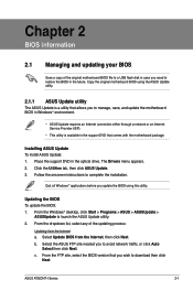
... you wish to download then click Next. Updating the BIOS To update the BIOS: 1. ASUS AT5IONT-I Series 2-1 Copy the original motherboard BIOS using this utility. Select the ASUS FTP site nearest you update the BIOS using the ASUS Update utility. 2.1.1 ASUS Update utility The ASUS Update is a utility that allows you to manage, save, and update the...
... you wish to download then click Next. Updating the BIOS To update the BIOS: 1. ASUS AT5IONT-I Series 2-1 Copy the original motherboard BIOS using this utility. Select the ASUS FTP site nearest you update the BIOS using the ASUS Update utility. 2.1.1 ASUS Update utility The ASUS Update is a utility that allows you to manage, save, and update the...
AT5IONT-I User's manual
Page 32
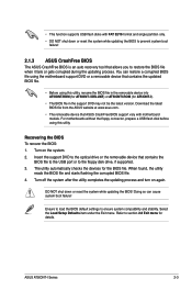
...reset the system while updating the BIOS to the floppy disk drive, if supported. 3. ASUS AT5IONT-I ). • The BIOS file in the removable device into AT5IONT.ROM (for AT5IONT-I DELUXE) or AT5IONTI.ROM (for AT5IONT-I Series 2-3 Insert the support DVD to restore the BIOS file when it fails or gets...to ensure system compatibility and stability. When found, the utility reads the BIOS file and starts flashing the corrupted BIOS file. 4. For motherboards without the floppy connector, prepare a USB flash disk before using this utility, rename the BIOS file in the support DVD may not be...
...reset the system while updating the BIOS to the floppy disk drive, if supported. 3. ASUS AT5IONT-I ). • The BIOS file in the removable device into AT5IONT.ROM (for AT5IONT-I DELUXE) or AT5IONTI.ROM (for AT5IONT-I Series 2-3 Insert the support DVD to restore the BIOS file when it fails or gets...to ensure system compatibility and stability. When found, the utility reads the BIOS file and starts flashing the corrupted BIOS file. 4. For motherboards without the floppy connector, prepare a USB flash disk before using this utility, rename the BIOS file in the support DVD may not be...
AT5IONT-I User's manual
Page 33
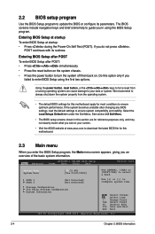
... back on the system chassis. • Press the power button to your screen. • Visit the ASUS website at startup: • Press during the Power-On Self Test (POST). Main Advanced AT5IONT-I DELUXE BIOS Setup Power Boot Tools Exit Version 0214 System Time [00:31:48] System Date [Tue.... Entering BIOS Setup after POST To enter BIOS Setup after changing any BIOS settings, load the default settings to configure system time. Do this motherboard. 2.3 Main menu When you enter the BIOS Setup program, the Main menu screen appears, giving you failed to enter BIOS Setup using the...
... back on the system chassis. • Press the power button to your screen. • Visit the ASUS website at startup: • Press during the Power-On Self Test (POST). Main Advanced AT5IONT-I DELUXE BIOS Setup Power Boot Tools Exit Version 0214 System Time [00:31:48] System Date [Tue.... Entering BIOS Setup after POST To enter BIOS Setup after changing any BIOS settings, load the default settings to configure system time. Do this motherboard. 2.3 Main menu When you enter the BIOS Setup program, the Main menu screen appears, giving you failed to enter BIOS Setup using the...
AT5IONT-I User's manual
Page 38
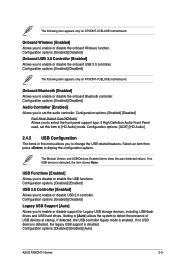
...to select the front panel support type. Configuration options: [Enabled] [Disabled] The following item appears only on AT5IONT-I DELUXE motherboard. USB Functions [Enabled] Allows you to enable or disable support for Legacy USB storage devices, including USB ...The following item appears only on AT5IONT-I DELUXE motherboard. Configuration options: [Enabled] [Disabled] Front Panel Support Type [HD Audio] Allows you to enable or disable the onboard USB 3.0 controller. Configuration options: [Disabled] [Enabled] [Auto] ASUS AT5IONT-I Series 2-9 Configuration options: [...
...to select the front panel support type. Configuration options: [Enabled] [Disabled] The following item appears only on AT5IONT-I DELUXE motherboard. USB Functions [Enabled] Allows you to enable or disable support for Legacy USB storage devices, including USB ...The following item appears only on AT5IONT-I DELUXE motherboard. Configuration options: [Enabled] [Disabled] Front Panel Support Type [HD Audio] Allows you to enable or disable the onboard USB 3.0 controller. Configuration options: [Disabled] [Enabled] [Auto] ASUS AT5IONT-I Series 2-9 Configuration options: [...


