AT5IONT-I User's manual
Page 3
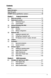
...this guide vi AT5IONT-I Series specifications summary viii Chapter 1: Product introduction 1.1 Before you proceed 1-1 1.2 Motherboard overview 1-2 1.2.1 Motherboard layout 1-2 1.2.2 Layout contents 1-3 1.3 Central Processing Unit (CPU 1-3 1.4 System memory 1-3 1.4.1 Overview 1-3 1.4.2 Memory configurations 1-4 ... DVD information 1-14 1.8.3 ASUS VideoSecurity 1-15 1.8.4 ASUS Home Theater Gate 1-17 1.8.5 ASUS @Vibe 1-20 Chapter 2: BIOS information 2.1 Managing and updating your BIOS 2-1 2.1.1 ASUS Update utility 2-1 2.1.2 ASUS EZ Flash 2 2-2 2.1.3 ASUS CrashFree BIOS 2-3 iii
...this guide vi AT5IONT-I Series specifications summary viii Chapter 1: Product introduction 1.1 Before you proceed 1-1 1.2 Motherboard overview 1-2 1.2.1 Motherboard layout 1-2 1.2.2 Layout contents 1-3 1.3 Central Processing Unit (CPU 1-3 1.4 System memory 1-3 1.4.1 Overview 1-3 1.4.2 Memory configurations 1-4 ... DVD information 1-14 1.8.3 ASUS VideoSecurity 1-15 1.8.4 ASUS Home Theater Gate 1-17 1.8.5 ASUS @Vibe 1-20 Chapter 2: BIOS information 2.1 Managing and updating your BIOS 2-1 2.1.1 ASUS Update utility 2-1 2.1.2 ASUS EZ Flash 2 2-2 2.1.3 ASUS CrashFree BIOS 2-3 iii
AT5IONT-I User's manual
Page 8
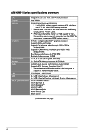
... technology Supports DVI with max. We recommend a maximum of 4GB capacity or more, the operating system may only recognize less than 3GB. AT5IONT-I Series specifications summary CPU Chipset Memory Graphics Expansion slot Storage Audio LAN USB ASUS special features Integrated Dual-Core Intel® Atom™ D525 processor Intel® NM10 Single channel...
... technology Supports DVI with max. We recommend a maximum of 4GB capacity or more, the operating system may only recognize less than 3GB. AT5IONT-I Series specifications summary CPU Chipset Memory Graphics Expansion slot Storage Audio LAN USB ASUS special features Integrated Dual-Core Intel® Atom™ D525 processor Intel® NM10 Single channel...
AT5IONT-I User's manual
Page 12
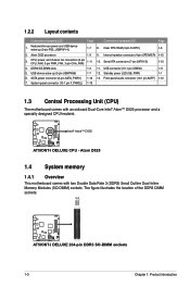
...™ D525 processor and a specially designed CPU heatsink. The figure illustrates the location of the DDR3 DIMM sockets: DIMM_A1 DIMM_A2 AT5IONT-I DELUXE AT5IONT-I DELUXE CPU - Standby power LED (SB_PWR) 1-1 6. System panel connector (10-1 pin F_PANEL) 1-13 1.3 Central Processing ...Unit (CPU) The motherboard comes with two Double Data Rate 3 (DDR3) Small Outline Dual Inline Memory Modules (SO-DIMM) sockets. D525 AT5IONT-I DELUXE AT5IONT-I DELUXE 204-pin DDR3 SO-DIMM sockets 1-3 Chapter 1: Product introduction USB connector (10-1 pin USB56) 1-11 5....
...™ D525 processor and a specially designed CPU heatsink. The figure illustrates the location of the DDR3 DIMM sockets: DIMM_A1 DIMM_A2 AT5IONT-I DELUXE AT5IONT-I DELUXE CPU - Standby power LED (SB_PWR) 1-1 6. System panel connector (10-1 pin F_PANEL) 1-13 1.3 Central Processing ...Unit (CPU) The motherboard comes with two Double Data Rate 3 (DDR3) Small Outline Dual Inline Memory Modules (SO-DIMM) sockets. D525 AT5IONT-I DELUXE AT5IONT-I DELUXE 204-pin DDR3 SO-DIMM sockets 1-3 Chapter 1: Product introduction USB connector (10-1 pin USB56) 1-11 5....
AT5IONT-I User's manual
Page 13
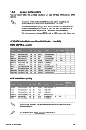
... - • • DDR3-1333 MHz capability Vendors Part No. D1288JELDPGD9U - - ASUS AT5IONT-I Series Motherboard Qualified Vendors Lists (QVL) DDR3-1067 MHz capability Vendors Part No. 1.4.2 Memory configurations You may install 512MB, 1GB, and 2GB unbuffered non‑ECC DDR3 SO-DIMMs...chips or less. J1108BDBG-DJ-F 9 1.5V J1108BDBG-DJ-F - - AT5IONT-I Series 1-4 H5TQ1G83TFR - - Visit the ASUS website at 800MHz on the motherboard, the actual usable memory for the latest QVL. Size APACER AS01GFA06C7NBGC 1GB HYNIX HMT112S6BFR6C-G7 1GB KINGSTON...
... - • • DDR3-1333 MHz capability Vendors Part No. D1288JELDPGD9U - - ASUS AT5IONT-I Series Motherboard Qualified Vendors Lists (QVL) DDR3-1067 MHz capability Vendors Part No. 1.4.2 Memory configurations You may install 512MB, 1GB, and 2GB unbuffered non‑ECC DDR3 SO-DIMMs...chips or less. J1108BDBG-DJ-F 9 1.5V J1108BDBG-DJ-F - - AT5IONT-I Series 1-4 H5TQ1G83TFR - - Visit the ASUS website at 800MHz on the motherboard, the actual usable memory for the latest QVL. Size APACER AS01GFA06C7NBGC 1GB HYNIX HMT112S6BFR6C-G7 1GB KINGSTON...
AT5IONT-I User's manual
Page 15
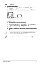
CLRTC 12 23 AT5IONT-I DELUXE Normal (Default) Clear RTC AT5IONT-I Series 1-6 Keep the cap on CLRTC jumper default position. Plug the power cord and turn ON the computer. 4. Removing the cap will cause system boot ... pins 2-3 for about 5-10 seconds, then move the jumper again to clear the CMOS RTC RAM data. ASUS AT5IONT-I DELUXE Clear RTC RAM To erase the RTC RAM: 1. 1.6 Jumpers 1. You can clear the CMOS memory of date, time, and system setup parameters by erasing the CMOS RTC RAM data. Hold down the key...
CLRTC 12 23 AT5IONT-I DELUXE Normal (Default) Clear RTC AT5IONT-I Series 1-6 Keep the cap on CLRTC jumper default position. Plug the power cord and turn ON the computer. 4. Removing the cap will cause system boot ... pins 2-3 for about 5-10 seconds, then move the jumper again to clear the CMOS RTC RAM data. ASUS AT5IONT-I DELUXE Clear RTC RAM To erase the RTC RAM: 1. 1.6 Jumpers 1. You can clear the CMOS memory of date, time, and system setup parameters by erasing the CMOS RTC RAM data. Hold down the key...
AT5IONT-I User's manual
Page 36
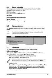
...the auto-detected CPU specification. Use the and keys to 250. BIOS Information Displays the auto-detected BIOS information. ASUS AT5IONT-I DELUXE BIOS Setup Power Boot Tools Exit JumperFree CPU Configuration Chipset Onboard Devices Configuration USB Configuration PCIPnP Version 0214 ...2.4.1 JumperFree The items in this menu. System Memory Displays the auto-detected system memory. 2.4 Advanced menu The Advanced menu items allow you to change the settings for the system. 2.3.6...
...the auto-detected CPU specification. Use the and keys to 250. BIOS Information Displays the auto-detected BIOS information. ASUS AT5IONT-I DELUXE BIOS Setup Power Boot Tools Exit JumperFree CPU Configuration Chipset Onboard Devices Configuration USB Configuration PCIPnP Version 0214 ...2.4.1 JumperFree The items in this menu. System Memory Displays the auto-detected system memory. 2.4 Advanced menu The Advanced menu items allow you to change the settings for the system. 2.3.6...
AT5IONT-I User's manual
Page 37
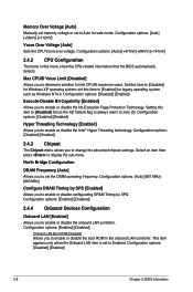
... to zero (0). Configuration options: [Enabled] [Disabled] Onboard LAN Boot ROM [Disabled] Allows you to enable or disable the No-Execution Page Protection Technology. Memory Over Voltage [Auto] Manually set memory voltage or set to Enabled. Configuration options: [Auto] [+56mV] [+112mV] Vcore Over Voltage [Auto] Sets the CPU Vcore over voltage. Configuration options...
... to zero (0). Configuration options: [Enabled] [Disabled] Onboard LAN Boot ROM [Disabled] Allows you to enable or disable the No-Execution Page Protection Technology. Memory Over Voltage [Auto] Manually set memory voltage or set to Enabled. Configuration options: [Auto] [+56mV] [+112mV] Vcore Over Voltage [Auto] Sets the CPU Vcore over voltage. Configuration options...
AT5IONT-I User's manual
Page 39
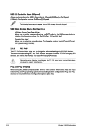
... USB 2.0 controller in the system. The menu includes setting IRQ and DMA channel resources for either PCI/PnP or legacy ISA devices, and setting the memory size block for boot. Configuration options: [FullSpeed] [HiSpeed] The following items may only appear when a USB storage device is plugged. Plug and Play O/S [No] When...
... USB 2.0 controller in the system. The menu includes setting IRQ and DMA channel resources for either PCI/PnP or legacy ISA devices, and setting the memory size block for boot. Configuration options: [FullSpeed] [HiSpeed] The following items may only appear when a USB storage device is plugged. Plug and Play O/S [No] When...


