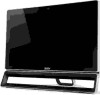
Acer Black Aspire ZS600
Related Manual Pages
Similar Questions

Acer Predator G7760 Mb-z68a01 - Black Screen.
No image at all. Black screen. Starts, then after 30 s- STOP&Restarts, Black screen, too. Change...
No image at all. Black screen. Starts, then after 30 s- STOP&Restarts, Black screen, too. Change...
(Posted by pisiku 1 year ago)

I Just Bought A Used Aspire All In One Zs600g And It Won't Boot Up. The Power Li
Comes on but the screen stays black
Comes on but the screen stays black
(Posted by wellsmichael3206 2 years ago)

Zs600g Blue Plwer Lite Comes On Black Screen Fan On Back Goes High Med,sppeed
The all-in-one started to do this after surge I'm thinking that I need to flash the bios but other d...
The all-in-one started to do this after surge I'm thinking that I need to flash the bios but other d...
(Posted by Oroblram796433 9 years ago)

Acer Aspire Z5761 Black Screen
Hi, Please help I have a Aspire Z5761 Desktop computer in which the screen has recently started goin...
Hi, Please help I have a Aspire Z5761 Desktop computer in which the screen has recently started goin...
(Posted by pauljudy 11 years ago)

Acer Aspire E700 Desktop Hangs On Black Screen That Reads 'please Wait......'
Hi, I have a Acer Aspire E700 Desktop with Vista OS. It is 4 years old, and so in the past when I'v...
Hi, I have a Acer Aspire E700 Desktop with Vista OS. It is 4 years old, and so in the past when I'v...
(Posted by tibtrungrung 12 years ago)
Related Terms
The following terms were also used when searching for Acer Black Aspire ZS600:- acer aspire zs600
- acer aspire zs600 10
- acer aspire zs600 23
- acer aspire zs600 6 beeps
- acer aspire zs600 all in one pc review
- acer aspire zs600 bios
- acer aspire zs600 bios key
- acer aspire zs600 black screen
- acer aspire zs600 boot menu
- acer aspire zs600 camera
- acer aspire zs600 disassembly
- acer aspire zs600 driver
- acer aspire zs600 drivers
- acer aspire zs600 factory reset
- acer aspire zs600 factory restore
- acer aspire zs600 graphics card
- acer aspire zs600 hard drive replacement
- acer aspire zs600 how to get it to stand
- acer aspire zs600 i3
- acer aspire zs600 i5
- acer aspire zs600 keyboard
- acer aspire zs600 manual
- acer aspire zs600 manual with windows 8
- acer aspire zs600 memory upgrade
- acer aspire zs600 memory upgrade instructions
- acer aspire zs600 motherboard
- acer aspire zs600 power supply
- acer aspire zs600 price
- acer aspire zs600 recovery
- acer aspire zs600 recovery partition
- acer aspire zs600 remove hard drive
- acer aspire zs600 repair
- acer aspire zs600 replace hard drive
- acer aspire zs600 service manual
- acer aspire zs600 specs
- acer aspire zs600 support
- acer aspire zs600 touch screen driver
- acer aspire zs600 touchscreen
- acer aspire zs600 tv tuner
- acer aspire zs600 tv tuner video
- acer aspire zs600 user guide
- acer aspire zs600 user manual
- acer aspire zs600 user's manual
- acer aspire zs600 users guide
- acer aspire zs600 wall mount
- acer aspire zs600 windows 7
- acer aspire zs600 windows 7 drivers
- acer aspire zs600g motherboard
- acer black aspire zs600
- aspire zs600
- aspire zs600 003
- aspire zs600 10
- aspire zs600 23
- aspire zs600 6 beeps
- aspire zs600 acer
- aspire zs600 all in one pc review
- aspire zs600 bios
- aspire zs600 bios key
- aspire zs600 black screen
- aspire zs600 boot from cd
- aspire zs600 boot menu
- aspire zs600 brightness
- aspire zs600 camera
- aspire zs600 disassembly
- aspire zs600 driver
- aspire zs600 drivers
- aspire zs600 factory reset
- aspire zs600 factory restore
- aspire zs600 graphics card
- aspire zs600 hard drive replacement
- aspire zs600 hdmi
- aspire zs600 how to get it to stand
- aspire zs600 how to sync keyboard and mouse
- aspire zs600 i3
- aspire zs600 i5
- aspire zs600 keyboard
- aspire zs600 manual
- aspire zs600 manual with windows 8
- aspire zs600 memory
- aspire zs600 memory upgrade
- aspire zs600 memory upgrade instructions
- aspire zs600 motherboard
- aspire zs600 no video
- aspire zs600 power supply
- aspire zs600 price
- aspire zs600 recovery
- aspire zs600 recovery partition
- aspire zs600 remove hard drive
- aspire zs600 repair
- aspire zs600 replace hard drive
- aspire zs600 service manual
- aspire zs600 sound card
- aspire zs600 specs
- aspire zs600 support
- aspire zs600 touch screen
- aspire zs600 touch screen driver
- aspire zs600 touchscreen
- aspire zs600 tv tuner
- aspire zs600 tv tuner video
- aspire zs600 user guide
- aspire zs600 user manual
- aspire zs600 user's manual
- aspire zs600 users guide
- aspire zs600 wall mount
- aspire zs600 webcam driver
- aspire zs600 windows 7
- aspire zs600 windows 7 drivers
- aspire zs600-005
- aspire zs600g motherboard
- buy acer aspire zs600
- buy aspire zs600