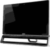
Acer Aspire ZS600 Desktop Service Guide
Page 5
... 2-32 DMI Tool Utilities 2-35 LAN EEPROM Utilities 2-40 CHAPTER 3 System Disassembly and Assembly Recommended Equipment 3-5 Pre-disassembly Procedure 3-5 Disassembly Process 3-6 Disassembly Flowchart 3-7 Removing the Stand 3-9 Removing the Rear Cover 3-11 Removing the HDD 3-15 Removing the Converter Board 3-16 Removing the ODD 3-17 Removing the Camera 3-19 Removing the OSD...
Acer Aspire ZS600 Desktop Service Guide
Page 6
... 3-50 Assembly Flowchart 3-51 Replacing the LCD 3-53 Replacing the IR 3-56 Replacing the Base Pan 3-57 Replacing the Left & Right Foot Stand (Power LED 3-60 Replacing the Motherboard 3-64 Replacing the System FAN 3-67 Replacing the CPU 3-70 Replacing the Memory 3-72 Replacing the WLAN...Converter Board 3-87 Replacing the HDD 3-90 Replacing the Heatsink 3-92 Replacing the Motherboard Shielding 3-94 Replacing the Rear Cover 3-96 Replacing the Stand 3-98 Thermal Pad location on base pan 3-100 Thermal Pad location on different VGA card 3-101 nVidia GT530 3-101 nVidia GT520 3-102 ...
Acer Aspire ZS600 Desktop Service Guide
Page 12
...-combo BD-rewrite Communication 0 WLAN: 802.11 a/b/g/n 2X2 WLAN LAN: Gigabit Ethernet WPAN: Bluetooth 4.0 LE Webcam: 2.0MP stand-alone webcam with 1920 x 1080 resolution TV-tuner 0 Acer TV-tuner options: Hybrid TV-tuner supporting worldwide dual DVB-T (Digital Video Broadcasting-Terrestrial) Hybrid TV-tuner...
Acer Aspire ZS600 Desktop Service Guide
Page 78
Machine Disassembly and Replacement 3-5 Recommended Equipment 3-5 Replacement Requirements 3-5 Disassembly Process 3-6 Disassembly Flowchart 3-7 Remove the Stand 3-8 Remove the ODD Bezel 3-10 Remove the Rear Cabinet 3-12 Remove the Motherboard Shielding 3-15 Remove the VESA Support Bracket 3-17 Remove ...the VGA Bracket 3-37 Remove the WLAN Card 3-39 Remove the Memory 3-41 Remove the CPU 3-42 Remove the Motherboard 3-43 Remove the Front Stand Bracket 3-46 Remove the WLAN Antenna Cables 3-51 Remove the Cushion Tape 3-53 Remove the Thermal Pads 3-54 Remove the LVDS Cable 3-55 ...
Acer Aspire ZS600 Desktop Service Guide
Page 79
Replace the CPU Blower 3-71 Replace the Thermal Pads 3-72 Replace the Cushion Tape 3-73 Replace the Base Pan 3-74 Replace the Front Stand Bracket 3-76 Replace the CPU 3-81 Replace the Memory 3-85 Replace the Motherboard 3-86 Replace the VGA Bracket 3-87 Replace the WLAN Card 3-88 Replace ... Bracket 3-109 Connect and route the cables 3-110 Replace the Motherboard Shielding 3-113 Replace the Rear Cabinet 3-115 Replace the ODD Bezel 3-116 Replace the Stand 3-118 3-3
Acer Aspire ZS600 Desktop Service Guide
Page 84
Figure 3-2. Stand 2. Release the latch, lift to remove the stand. 3-8 Remove the Stand 0 1. Remove 3 screws to remove hinge cover. Stand Figure 3-3.
Acer Aspire ZS600 Desktop Service Guide
Page 122
Remove the Front Stand Bracket 0 1. Turn over the bracket, remove 2 screws on front stand right bracket. Front Stand Right Bracket Table 3-20. Front Stand Right Bracket Figure 3-66. Screws Step Front Stand Right Bracket Removal Screw M3*5 Quantity 3 M3*6 2 Screw Type 2. Remove 5 screws on power switch holder. 3-46 Figure 3-65.
Acer Aspire ZS600 Desktop Service Guide
Page 123
Front Stand Right Bracket Table 3-21. Screws Step Power Switch Holder Removal Screw M3*5 Quantity 2 3. Separate the power switch holder from power button cable. Front Stand Right Bracket 4. Figure 3-67. Screw Type Figure 3-68. Remove the bracket by passing power button cable through the bracket hole. 3-47
Acer Aspire ZS600 Desktop Service Guide
Page 125
Front Stand Middle Bracket 3-49 Screw Type Figure 3-72. Screws Step Front Stand Left Bracket Removal Screw M3*5 Quantity 3 M3*6 2 6. Front Stand Middle Bracket Figure 3-73. Figure 3-71. Release 4 screws to remove front stand middle bracket. Front Stand Left Bracket Table 3-22.
Acer Aspire ZS600 Desktop Service Guide
Page 126
Screws Step Front Stand Middle Bracket Removal Screw M3*6 Quantity 4 Screw Type 3-50 Table 3-23.
Acer Aspire ZS600 Desktop Service Guide
Page 152
Figure 3-113. Pass the power button cable through front stand right bracket. Pull power button cable to position power switch holder on the bracket, consolidate the holder with power button cable. Combine power switch holder with 2 screws. 3-76 Front Stand Right Bracket 2. Front Stand Right Bracket 3. Figure 3-112. Replace the Front Stand Bracket 0 1.
Acer Aspire ZS600 Desktop Service Guide
Page 153
Turn over the bracket and position it on the bottom of front bezel. Front Stand Right Bracket Table 3-29. Screws Step Power Switch Holder Replacement Screw M3*5 Quantity 2 4. Figure 3-114. Front Stand Right Bracket 5. Screw Type Figure 3-115. Consolidate the bracket with 5 screws. 3-77
Acer Aspire ZS600 Desktop Service Guide
Page 155
Consolidate the bracket with 5 screws. Figure 3-118. Front Stand Left Bracket 7. Front Stand Left Bracket 3-79 Figure 3-119.
Acer Aspire ZS600 Desktop Service Guide
Page 194
Screws Step Stand Replacement M4*6 Screw 2. Replace the Stand 0 1. Figure 3-180. Replace the hinge cover. Quantity 3 Screw Type Figure 3-181. Position the stand on the rear cabinet, consolidate the stand with 3 screws. Stand Table 3-50. Hinge Cover 3-118
Acer Aspire ZS600 Desktop Service Guide
Page 229
Table 6-1. Item 2 Part Name PARIS_II A 23 STAND ASM 3 PARIS A 23 REAR CABINET ASM 4 PARIS A 23 BKT VESA SUPPORT 5 PARIS 23 HDD CAGE 6 PARIS 23 HDD GROMMET 7 HDD SATA3 7200R 1TB 3.5' CC4B HDD ...-OSD/RAY 13 SPEAKER 23'APARIS 14 WLAN CBL 1P L:650mm AM8-9 15 PARIS 23 ANTENNA MYLAR 16 PARIS A 23 BKT FR STAND RIGHT 17 PARIS A 23 BKT FRONT STAND MID 18 PARIS_II A 23 PANEL BKT B 19 PARIS_II A 23 VHB BOTTOM 20 PARIS_II A 23 PANEL BKT R 21 PARIS_II A 23 VHB SIDE 22...
Acer Aspire ZS600 Desktop Service Guide
Page 236
MIDDLE MB SHIELDING P/N 42.SKMD5.002 42.SHL0U.006 42.VEDD5.002 33.SHL0U.002 33.SHL0U.003 MB/VGA BRACKET HDD CAGE ODD CAGE 33.U6N0U.010 33.U6N0U.003 33.U6Q0U.008 6-12 FRU (Field Replaceable Unit) List Table 6-2. FRU list Category HINGE COVER Description POWER SWITCH HOLDER SIDE BEZEL W/O B CAS STAND FRONT BRACKET -
Acer Aspire ZS600 Desktop Service Guide
Page 237
Table 6-2. FRU list Category Description STAND FRONT BRACKET - R BRACKET VESA SUPPORT Thermal HEAT PIPE FAN P/N 33.SHL0U.004 33.SHL0U.005 33.SHL0U.006 60.U6N0U.003 23.U6N0U.002 CPU CPU(PGA) Intel Core i7 3770S LGA 3.1G 8M 1333 1155 65W Quad Core KC.37701.SI7 Memory FRU (Field Replaceable Unit) List 6-13 L STAND FRONT BRACKET -
User Guide
Page 3
... a built-in a fire or electric shock. The openings should never be sure to prevent battery leakage, do not place the product on an unstable cart, stand or table. Follow all power cords from the power supplies. Unplug the power cord before removing the power supply unit from the computer. CAUTION for...
User Guide
Page 7
...and the ENERGY STAR mark are also at risk of physical injury after long hours of working conditions, personal health and other musculoskeletal disorders. vii Acer ENERGY STAR qualified products: • Produce less heat and reduce cooling loads, and warmer climates. • Automatically go into "display sleep".... • Wake the computer from staying too long in one fixed posture. • Avoid slouching forward and/or leaning backward. • Stand up and walk around regularly to remove the strain on your leg muscles. • Take short rests to relax your neck and shoulders. •...
User Guide
Page 13
..., line-in and line-out jacks (configuration may be stepped on. • Avoid placing the system in the upright position. CAUTION: Please use the foot stand when placing your computer: • Do not place the system too close to other electrical equipment. • Do not place the system in high-traffic...