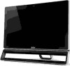
Acer Aspire ZS600 Desktop Service Guide
Page 5
CHAPTER 1 Hardware Specifications Features 1-3 Quick Specification 1-3 Chassis Specification 1-7 Motherboard Specification 1-10 System Tour 1-15 M/B Placement 1-20 Jumper Setting 1-21 Block Diagram 1-23 CHAPTER 2 System Utilities CMOS Setup Utility 2-3 Entering CMOS setup 2-4 Navigating Through the ... 3-11 Removing the HDD 3-15 Removing the Converter Board 3-16 Removing the ODD 3-17 Removing the Camera 3-19 Removing the OSD Board 3-20 Removing the Motherboard Shielding 3-21 Removing the Display Card 3-23 Removing the Memory 3-26 ii-v
Acer Aspire ZS600 Desktop Service Guide
Page 6
... LCD 3-53 Replacing the IR 3-56 Replacing the Base Pan 3-57 Replacing the Left & Right Foot Stand (Power LED 3-60 Replacing the Motherboard 3-64 Replacing the System FAN 3-67 Replacing the CPU 3-70 Replacing the Memory 3-72 Replacing the WLAN 3-73 Replacing the Display Card 3-75... the Camera 3-83 Replacing the ODD 3-85 Replacing the Converter Board 3-87 Replacing the HDD 3-90 Replacing the Heatsink 3-92 Replacing the Motherboard Shielding 3-94 Replacing the Rear Cover 3-96 Replacing the Stand 3-98 Thermal Pad location on base pan 3-100 Thermal Pad location on different...
Acer Aspire ZS600 Desktop Service Guide
Page 16
...61548;1 DC in jack 1 RJ45 connector (support Giga LAN) 1 S/PDIF Connector 1 Coaxial (NTSC/PAL) connector Motherboard Mounting Feature 0 Features for LED Backlight ON/OFF control and LCD signal source selection (from MB or HDMI in port) Rear I /O Connector... 1; bootable) 1 mini B-CAS Card Reader (push-push; JP SKU only) 2 Switches for mounting 190*230mm2 motherboard Power Supply Mounting Feature 0 External power adapter 1-8 Hardware Specifications and Configurations
Acer Aspire ZS600 Desktop Service Guide
Page 19
Motherboard Specification 0 RoHS Should be compliant with RoHS EuP Should be compliant with EuP Lot6 Size 190*230mm2 Certification Microsoft MDA 2010 compliant HDMI 1.4a Certificate fee paid by MB vendor Brand Logo "Acer Inc" logo Printed on the...
Acer Aspire ZS600 Desktop Service Guide
Page 23
... or 3.0 connectors. (BOM option) On-board connectors 1 ILM+SKT+BP for LGA 1155 CPU (assign by Acer) 1 9Pin LCD Panel Power Supply Connector 2 SO-DDR3 memory sockets 1 90 Degree PCI-E x16 ...;1 3Pin CIR header (support RC6 / RCMM) 1 on board buzzer Acer Hardware spec 0 Please follow: Acer Desktop H/W Validation Request rev 2.7 Acer Motherboard EE Design Request v3.7 Hardware Specifications and Configurations 1-15 4 USB 2.0 ports...
Acer Aspire ZS600 Desktop Service Guide
Page 78
... Replacement Requirements 3-5 Disassembly Process 3-6 Disassembly Flowchart 3-7 Remove the Stand 3-8 Remove the ODD Bezel 3-10 Remove the Rear Cabinet 3-12 Remove the Motherboard Shielding 3-15 Remove the VESA Support Bracket 3-17 Remove the HDD Module 3-19 Remove the ODD Module 3-22 Remove the Speaker 3-25 Remove the ...Card 3-35 Remove the VGA Bracket 3-37 Remove the WLAN Card 3-39 Remove the Memory 3-41 Remove the CPU 3-42 Remove the Motherboard 3-43 Remove the Front Stand Bracket 3-46 Remove the WLAN Antenna Cables 3-51 Remove the Cushion Tape 3-53 Remove the Thermal Pads...
Acer Aspire ZS600 Desktop Service Guide
Page 79
... the Cushion Tape 3-73 Replace the Base Pan 3-74 Replace the Front Stand Bracket 3-76 Replace the CPU 3-81 Replace the Memory 3-85 Replace the Motherboard 3-86 Replace the VGA Bracket 3-87 Replace the WLAN Card 3-88 Replace the VGA Card 3-90 Replace the Convert Board 3-92 Replace the ODD Module... HDD Module 3-99 Replace the Heatsink 3-103 Replace the Speaker 3-105 Replace the VESA Support Bracket 3-109 Connect and route the cables 3-110 Replace the Motherboard Shielding 3-113 Replace the Rear Cabinet 3-115 Replace the ODD Bezel 3-116 Replace the Stand 3-118 3-3
Acer Aspire ZS600 Desktop Service Guide
Page 91
Remove the Motherboard Shielding 0 1. Motherboard Shielding Figure 3-13. Motherboard Shielding Table 3-4. Screws Step Motherboard Shielding Removal M3*5 Screw Quantity 12 Screw Type 3-15 Remove 12 screws on motherboard shielding. Figure 3-12.
Acer Aspire ZS600 Desktop Service Guide
Page 92
Figure 3-14. 2. Motherboard Shielding Figure 3-15. Motherboard Shielding 3-16 Lift to remove motherboard shielding.
Acer Aspire ZS600 Desktop Service Guide
Page 101
Speaker 2. Pull out the right speaker cable from motherboard, pull speaker cable out of the base pan hole. Speaker 3. Remove 4 screws on 2 speakers. 3-25 Figure 3-30. Disconnect speaker cable from the stuck groove and metal hook. Figure 3-31. Remove the Speaker 0 1.
Acer Aspire ZS600 Desktop Service Guide
Page 106
Disconnect CPU blower cable from base pan. CPU Blower 2. Remove 3 screws on CPU blower and remove the blower from motherboard. Screws Step CPU Blower Removal M3*5 Screw Quantity 3 Screw Type 3-30 CPU Blower Table 3-12. Figure 3-38. Remove the CPU Blower 0 1. Figure 3-39.
Acer Aspire ZS600 Desktop Service Guide
Page 111
Figure 3-47. Screws Step VGA Lock Removal Screw M3*5 Quantity 1 Screw Type 3-35 Release 1 screw to disconnect it from PCI-E slot of VGA card. Figure 3-46. VGA Holder 2. Push the VGA card forward to rotate the VGA lock. VGA Card Table 3-15. Remove the VGA Card 0 1. Rotate the VGA holder clockwise to release the left part of motherboard.
Acer Aspire ZS600 Desktop Service Guide
Page 113
VGA Bracket Table 3-16. Camera Cable 2. Figure 3-49. Figure 3-50. Lift to remove VGA bracket. Remove 2 screws on VGA bracket. Quantity 2 Screw Type 3-37 Screws Step Screw VGA Bracket Removal M3*5 3. Remove the VGA Bracket 0 1. Disconnect camera cable from motherboard, tear off the acetate fabric from the VGA bracket.
Acer Aspire ZS600 Desktop Service Guide
Page 117
Figure 3-56. Memory 3-41 Memory Figure 3-57. Remove the Memory 0 1. Follow numeric ascending order to remove the memory banks from motherboard.
Acer Aspire ZS600 Desktop Service Guide
Page 118
Figure 3-58. CPU 3-42 Remove CPU from the LGA socket of motherboard. CPU Figure 3-59. Remove the CPU 0 1.
Acer Aspire ZS600 Desktop Service Guide
Page 119
Conductive Fabric 2. Figure 3-61. Tear off the conductive fabric on LVDS cable and convert cable. Disconnect the cables from motherboard. Disconnect LVDS cable and convert cable from motherboard. 3-43 Motherboard 3. Figure 3-60. Remove the Motherboard 0 1.
Acer Aspire ZS600 Desktop Service Guide
Page 120
Disconnect IR cable from motherboard, pull IR cable out of the gap between USB connectors. Motherboard Table 3-18. Figure 3-63. IR Cable 3-44 Figure 3-62. Cables connecting to motherboard(Partial) Connector in frame Cable linking to connector Yellow OSD cable(5-pin) Green CPU blower cable(4-pin) Orange SATA power cable(4-pin) Red(upper) SATA cable(ODD, 300mm, L-shaped port, 7-pin) Red(lower) SATA cable(HDD, 190mm, L-shaped port, 7-pin) Blue Power button cable(10-pin) Purple PCT touch cable(4-pin) 4.
Acer Aspire ZS600 Desktop Service Guide
Page 121
Screws Step Motherboard Removal Screw M3*5 Quantity 6 Screw Type 3-45 Motherboard Table 3-19. Figure 3-64. Remove 6 screws on motherboard and lift to remove motherboard from base pan. 5.
Acer Aspire ZS600 Desktop Service Guide
Page 157
Replace the CPU 0 1. Replace the CPU on the LGA socket of LGA package to socket, please follow the steps below. Figure 3-120. Figure 3-121. CPU NOTE: NOTE: To assemble CPU of motherboard. Replace CPU Step 1 3-81
Acer Aspire ZS600 Desktop Service Guide
Page 161
Memory 3-85 Figure 3-127. Insert one memory bar to the lower socket of motherboard first, press to the upper socket. And assemble the other memory bar to click it into the spring lock. Replace the Memory 0 1.