
Acer Aspire X3990 Desktop Service Guide
Page 8
System Troubleshooting 69 Hardware Diagnostic Procedure 69 System Check Procedures 70 Power System Check 70 System External Inspection 70 System Internal Inspection 70 Beep Codes 71 Checkpoints 72 BIOS Recovery 75 Jumper and Connector Information 76 M/B Placement 76 Jumper Setting 78 Setting Jumper 78 FRU (Field Replaceable Unit) List 85 Aspire X3990 Exploded Diagram 86 Aspire X3990 FRU List 88 viii
System Troubleshooting 69 Hardware Diagnostic Procedure 69 System Check Procedures 70 Power System Check 70 System External Inspection 70 System Internal Inspection 70 Beep Codes 71 Checkpoints 72 BIOS Recovery 75 Jumper and Connector Information 76 M/B Placement 76 Jumper Setting 78 Setting Jumper 78 FRU (Field Replaceable Unit) List 85 Aspire X3990 Exploded Diagram 86 Aspire X3990 FRU List 88 viii
Acer Aspire X3990 Desktop Service Guide
Page 19
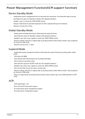
...sync to control the VESA DPMS monitor. • Resume method:device activated (keyboard for DOS, keyboard &mouse for Windows. • Resume recovery time 3-5sec Global Standby Mode • Global power management timer(2-120minutes,time step=10minute). • Hard disk drive goes into Standby mode(... Resume method: Resume to original state by pushing external switch Button,modem ring in,keyboard an mouse for APM mode. • Resume recovery time :7-10sec Suspend Mode • Independent power management timer(2-120minutes,time step=10minute)or pushing extern switch button. • CPU goes ...
...sync to control the VESA DPMS monitor. • Resume method:device activated (keyboard for DOS, keyboard &mouse for Windows. • Resume recovery time 3-5sec Global Standby Mode • Global power management timer(2-120minutes,time step=10minute). • Hard disk drive goes into Standby mode(... Resume method: Resume to original state by pushing external switch Button,modem ring in,keyboard an mouse for APM mode. • Resume recovery time :7-10sec Suspend Mode • Independent power management timer(2-120minutes,time step=10minute)or pushing extern switch button. • CPU goes ...
Acer Aspire X3990 Desktop Service Guide
Page 80
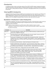
... is done. Go to checkpoint E0. Adjust policies and cache first 8MB. Performs main BIOS checksum and updates recovery status accordingly. If BIOS recovery is necessary,control flows to flat mode with 4GB limit and GA20 enabled. The Bootblock-Runtime interface module is moved...checked to memory in cards that may change due to vendor requirements,system chipset or option ROMs from this point. See Bootblock Recovery Code Checkpoints sectionfor more information. Bootblock Initialization Code Checkpoints The Bootblock initialization code sets up the chipset,memory, and other CPU...
... is done. Go to checkpoint E0. Adjust policies and cache first 8MB. Performs main BIOS checksum and updates recovery status accordingly. If BIOS recovery is necessary,control flows to flat mode with 4GB limit and GA20 enabled. The Bootblock-Runtime interface module is moved...checked to memory in cards that may change due to vendor requirements,system chipset or option ROMs from this point. See Bootblock Recovery Code Checkpoints sectionfor more information. Bootblock Initialization Code Checkpoints The Bootblock initialization code sets up the chipset,memory, and other CPU...

Acer Aspire X3990 Desktop Service Guide
Page 82
...F0 F1 F2 F3 F5 FA FB F4 FC FD FF Description Initialize the floppy controller in root directory. Search for pre-defined recovery file name in the super I/O. Detect proper flash part. Disable ATAPI hardware. Attempt to read from floppy. Disable ATAPI hardware. ... vectors are initialized. Give control to checkpoint E9. Make flash write disabled. DMA controller is initialized. 8259 interrupt controller is enabled. Recovery file not found flash part size. The following table describes the type of the flash part. Attempt to find the clusters occupied by...
...F0 F1 F2 F3 F5 FA FB F4 FC FD FF Description Initialize the floppy controller in root directory. Search for pre-defined recovery file name in the super I/O. Detect proper flash part. Disable ATAPI hardware. Attempt to read from floppy. Disable ATAPI hardware. ... vectors are initialized. Give control to checkpoint E9. Make flash write disabled. DMA controller is initialized. 8259 interrupt controller is enabled. Recovery file not found flash part size. The following table describes the type of the flash part. Attempt to find the clusters occupied by...

Acer Aspire X3990 Desktop Service Guide
Page 83
The BIOS recovery function will auto reboot. 6. After BIOS is used to flash update a BIOS from the boot block. Chapter 4 75 This is updated completely, the system will ... to boot the system and then press Ctrl + Home. 4. Press power button to the system. 3. Put the AMIBoot.ROM to flash BIOS ROM. 1. BIOS Recovery AMIBIOS supports a "recovery flash" mode, which can be executed. 5. The following is the process that user should follow to a bootable USB flash drive(Disk on Key, DOK...
The BIOS recovery function will auto reboot. 6. After BIOS is used to flash update a BIOS from the boot block. Chapter 4 75 This is updated completely, the system will ... to boot the system and then press Ctrl + Home. 4. Press power button to the system. 3. Put the AMIBoot.ROM to flash BIOS ROM. 1. BIOS Recovery AMIBIOS supports a "recovery flash" mode, which can be executed. 5. The following is the process that user should follow to a bootable USB flash drive(Disk on Key, DOK...
Acer Aspire X3990 Desktop Service Guide
Page 88
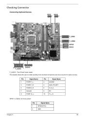
Pin Signal Name 1 PORT-F_L 3 PORT-F_R 5 PORT-E_R 7 SenseB 9 PORT -E_L Pin Signal Name 2 AUGND 4 AUD_FP_DET 6 F_R_A 8 NC 10 F_L_A GPIO1~2: Button recovery jumper Pin Signal Name 1 GP36(GP16) 2 GND Chapter 5 80 Checking Connector Connecting Optional Devices F_AUDIO: Front Panel Audio heade This header allows the user to install auxiliary front-oriented microphone and line-out ports for easier access.
Pin Signal Name 1 PORT-F_L 3 PORT-F_R 5 PORT-E_R 7 SenseB 9 PORT -E_L Pin Signal Name 2 AUGND 4 AUD_FP_DET 6 F_R_A 8 NC 10 F_L_A GPIO1~2: Button recovery jumper Pin Signal Name 1 GP36(GP16) 2 GND Chapter 5 80 Checking Connector Connecting Optional Devices F_AUDIO: Front Panel Audio heade This header allows the user to install auxiliary front-oriented microphone and line-out ports for easier access.

