Acer Aspire X3990 Desktop Service Guide
Page 7
... Install the Processor 50 Install the Memory 51 Install the Heat Sink Fan Assembly 52 Romoving the Side Panel 53 Romoving the Front Bezel 54 Removing the Cage of ODD and HDD 55 Install the Power Supply 56 Install the I/O Shielding 57 Install the Main Board 58 Connect the Cable 59 Install the Optical Drive 61 Install the Hard Disk Drive 62 Install the Cage of ODD and HDD 63 Install the Front Bezel 65 Install the VGA Card 66 Install...
... Install the Processor 50 Install the Memory 51 Install the Heat Sink Fan Assembly 52 Romoving the Side Panel 53 Romoving the Front Bezel 54 Removing the Cage of ODD and HDD 55 Install the Power Supply 56 Install the I/O Shielding 57 Install the Main Board 58 Connect the Cable 59 Install the Optical Drive 61 Install the Hard Disk Drive 62 Install the Cage of ODD and HDD 63 Install the Front Bezel 65 Install the VGA Card 66 Install...
Acer Aspire X3990 Desktop Service Guide
Page 8
System Troubleshooting 69 Hardware Diagnostic Procedure 69 System Check Procedures 70 Power System Check 70 System External Inspection 70 System Internal Inspection 70 Beep Codes 71 Checkpoints 72 BIOS Recovery 75 Jumper and Connector Information 76 M/B Placement 76 Jumper Setting 78 Setting Jumper 78 FRU (Field Replaceable Unit) List 85 Aspire X3990 Exploded Diagram 86 Aspire X3990 FRU List 88 viii
System Troubleshooting 69 Hardware Diagnostic Procedure 69 System Check Procedures 70 Power System Check 70 System External Inspection 70 System Internal Inspection 70 Beep Codes 71 Checkpoints 72 BIOS Recovery 75 Jumper and Connector Information 76 M/B Placement 76 Jumper Setting 78 Setting Jumper 78 FRU (Field Replaceable Unit) List 85 Aspire X3990 Exploded Diagram 86 Aspire X3990 FRU List 88 viii
Acer Aspire X3990 Desktop Service Guide
Page 9
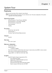
... Type: DDR III • Socket Quantity: 2 • 1 channels, 2 DIMMs • Dual channel should be enabled always when plug-in this section is for your reference only. Graphic • Intel® HD Graphics Support (supported by CPU). • Dual independent display. • Digital display (HDMI/DVI/DP/eDP) and VGA. • DVMT 5.0 technology support. • Enhanced 3D and Clear Video technology support. • Need to measure VGA follow Acer VGA SOP. The exact configuration...
... Type: DDR III • Socket Quantity: 2 • 1 channels, 2 DIMMs • Dual channel should be enabled always when plug-in this section is for your reference only. Graphic • Intel® HD Graphics Support (supported by CPU). • Dual independent display. • Digital display (HDMI/DVI/DP/eDP) and VGA. • DVMT 5.0 technology support. • Enhanced 3D and Clear Video technology support. • Need to measure VGA follow Acer VGA SOP. The exact configuration...
Acer Aspire X3990 Desktop Service Guide
Page 10
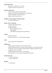
...; Intel Lewisville 82579V GigaLAN PHY USB ports • Supports at least 10 USB ports on both front and rear side. • At least 6 USB ports located on rear panel and others located on board buzzer 2 Chapter 1 Serial ATA controller • Connector Type: SATA connector. • Connector Quantity: 2 • Storage Type support: • HDD : Support RAID 0/1/5/10. • Blue Ray ODD. • AHCI/RAID mode supported for internal SATA port. Hard disk drive • Support up to one SATA 5.25" standard ODD. • Support DVD-ROM, DVD-SuperMulti, BD-combo, BD...
...; Intel Lewisville 82579V GigaLAN PHY USB ports • Supports at least 10 USB ports on both front and rear side. • At least 6 USB ports located on rear panel and others located on board buzzer 2 Chapter 1 Serial ATA controller • Connector Type: SATA connector. • Connector Quantity: 2 • Storage Type support: • HDD : Support RAID 0/1/5/10. • Blue Ray ODD. • AHCI/RAID mode supported for internal SATA port. Hard disk drive • Support up to one SATA 5.25" standard ODD. • Support DVD-ROM, DVD-SuperMulti, BD-combo, BD...
Acer Aspire X3990 Desktop Service Guide
Page 11
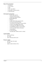
...+MS • 1 * VGA connector • 1 * HDMI • 1 * RJ45 + Dual USB2.0 • 1 * Qual USB2.0 connector (4 ports) • 1 * 3 ports Audio jack On-board connectors • 1 * ILM for LGA 1155 CPU. • 1 * 24-pin ATX PWR connector. • 1 * H2X4 Power Supply Connector. • 2* DDR3 DIMM Socket. • 2 * SATA 2.0. • 4 * USB2.0 H5X2 Header (support 8 ports). • 1 * Front Audio Pannel H5X2 header. • 1 * Front Panel IO H7X2 Header for Acer pin define. • 1 * H1X4 CPU with SAMRT FAN controller. • 1 * H1X4...
...+MS • 1 * VGA connector • 1 * HDMI • 1 * RJ45 + Dual USB2.0 • 1 * Qual USB2.0 connector (4 ports) • 1 * 3 ports Audio jack On-board connectors • 1 * ILM for LGA 1155 CPU. • 1 * 24-pin ATX PWR connector. • 1 * H2X4 Power Supply Connector. • 2* DDR3 DIMM Socket. • 2 * SATA 2.0. • 4 * USB2.0 H5X2 Header (support 8 ports). • 1 * Front Audio Pannel H5X2 header. • 1 * Front Panel IO H7X2 Header for Acer pin define. • 1 * H1X4 CPU with SAMRT FAN controller. • 1 * H1X4...
Acer Aspire X3990 Desktop Service Guide
Page 15
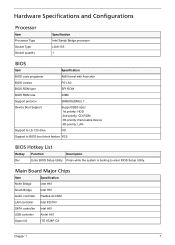
... Specifications and Configurations Processor Item Processor Type Socket Type Socket quantity Specification Intel Sandy Bridge processor LGA1155 1 BIOS Item Specification BIOS code programer AMI Kernel with Acer skin BIOS version P01-A0 BIOS ROM type SPI ROM BIOS ROM size 32Mb Support protocol SMBIOS(DMI)2.7 Device Boot Support Support BBS spec: 1st priority: HDD 2nd priority: CD-ROM 3th priority: Removable Device 4th priority: LAN Support to LS-120 drive NO Support to BIOS boot block feature YES BIOS Hotkey List Hotkey Function Description Del Enter BIOS Setup Utility...
... Specifications and Configurations Processor Item Processor Type Socket Type Socket quantity Specification Intel Sandy Bridge processor LGA1155 1 BIOS Item Specification BIOS code programer AMI Kernel with Acer skin BIOS version P01-A0 BIOS ROM type SPI ROM BIOS ROM size 32Mb Support protocol SMBIOS(DMI)2.7 Device Boot Support Support BBS spec: 1st priority: HDD 2nd priority: CD-ROM 3th priority: Removable Device 4th priority: LAN Support to LS-120 drive NO Support to BIOS boot block feature YES BIOS Hotkey List Hotkey Function Description Del Enter BIOS Setup Utility...
Acer Aspire X3990 Desktop Service Guide
Page 16
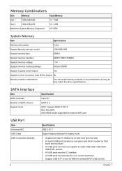
... Memory module combinations You can install memory modules in any combination as long as they match the above specifications. SATA Interface Item SATA controller Number of SATA channel Support mode Specification Intel H61 SATA X 2 HDD : Support RAID 0/1/5/10 Blue Ray ODD AHCI/RAID mode supported for internal SATA port USB Port Item Universal HCI USB Class USB Connectors Quantity 8 Specification USB 2.0/1.1 Support legacy keyboard for legacy mode • Supports at least 10 USB ports on both front and rear side. • At least 6 USB ports located on rear panel and others located...
... Memory module combinations You can install memory modules in any combination as long as they match the above specifications. SATA Interface Item SATA controller Number of SATA channel Support mode Specification Intel H61 SATA X 2 HDD : Support RAID 0/1/5/10 Blue Ray ODD AHCI/RAID mode supported for internal SATA port USB Port Item Universal HCI USB Class USB Connectors Quantity 8 Specification USB 2.0/1.1 Support legacy keyboard for legacy mode • Supports at least 10 USB ports on both front and rear side. • At least 6 USB ports located on rear panel and others located...

Acer Aspire X3990 Desktop Service Guide
Page 17
...; "Software selectable boost gain (+10/+20/+30dB) for analog microphone input • "Two jack detection pins: each supports detection of up to 4 jacks • "Jack detection function is supported when device is in power down mode (D3) • "Supports two GPIO pins (general purpose input and output) • "Supports EAPD (external amplifier power down) control for external amplifier • "Support 1.5V~3.3V scalable I/O for HD Audio...
...; "Software selectable boost gain (+10/+20/+30dB) for analog microphone input • "Two jack detection pins: each supports detection of up to 4 jacks • "Jack detection function is supported when device is in power down mode (D3) • "Supports two GPIO pins (general purpose input and output) • "Supports EAPD (external amplifier power down) control for external amplifier • "Support 1.5V~3.3V scalable I/O for HD Audio...
Acer Aspire X3990 Desktop Service Guide
Page 19
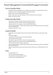
... in,keyboard an mouse for APM mode. • Resume recovery time :7-10sec Suspend Mode • Independent power management timer(2-120minutes,time step=10minute)or pushing extern switch button. • CPU goes into SMM • CPU asserts STPCLK# and goes into the Stop Grant State. • LED on panel turns amber colour. • Hard disk drive goes into SLEEP mode (for ATA standard interface). • Disable H-sync and V-sync signals to control the...
... in,keyboard an mouse for APM mode. • Resume recovery time :7-10sec Suspend Mode • Independent power management timer(2-120minutes,time step=10minute)or pushing extern switch button. • CPU goes into SMM • CPU asserts STPCLK# and goes into the Stop Grant State. • LED on panel turns amber colour. • Hard disk drive goes into SLEEP mode (for ATA standard interface). • Disable H-sync and V-sync signals to control the...
Acer Aspire X3990 Desktop Service Guide
Page 20
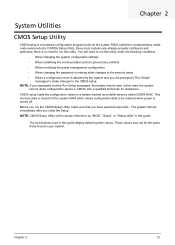
... CMOS. You will be retained when power is turned off. This memory area is not part of the system RAM which allows configuration data to make sure that you close the Setup. Since most systems are prompted ("Run Setup" message) to be simply referred to run this guide. The screenshots used in this case, the system cannot retain configuration values in your system. Chapter 2 System Utilities CMOS Setup Utility CMOS setup is a hardware configuration...
... CMOS. You will be retained when power is turned off. This memory area is not part of the system RAM which allows configuration data to make sure that you close the Setup. Since most systems are prompted ("Run Setup" message) to be simply referred to run this guide. The screenshots used in this case, the system cannot retain configuration values in your system. Chapter 2 System Utilities CMOS Setup Utility CMOS setup is a hardware configuration...

Acer Aspire X3990 Desktop Service Guide
Page 22
.... Serial number of system memory installed on the system. Date when the BIOS setup utility was built Type of the BIOS setup utility. Parameter System BIOS Version Build Date Processor Core Frequency Count Memory Size Product Name System Serial Number Asset Tag Number System Date System Time (hh:mm:ss) Description Version number of CPU installed on the system. Product name of the menu screenshots, settings in boldface are the default and suggested settings. Setup Utility...
.... Serial number of system memory installed on the system. Date when the BIOS setup utility was built Type of the BIOS setup utility. Parameter System BIOS Version Build Date Processor Core Frequency Count Memory Size Product Name System Serial Number Asset Tag Number System Date System Time (hh:mm:ss) Description Version number of CPU installed on the system. Product name of the menu screenshots, settings in boldface are the default and suggested settings. Setup Utility...

Acer Aspire X3990 Desktop Service Guide
Page 30
... an error during startup. Boot Options 1st/2nd/3rd/4th/5th Boot Device EFI Device Priority Hard Disk Drive Priority Optical Disk Drive Priority Removable Device Priority Network Device Priority Quiet Boot Halt On Specifies the boot order from available EFI devices. Press Enter to access the Hard Disk Drive Priority submenu and specify the boot device priority sequence from available optical drives. Press Enter to access the Network Device Priority submenu and specify the boot device priority sequence from available removable drives. When disabled, the diagnostic screen...
... an error during startup. Boot Options 1st/2nd/3rd/4th/5th Boot Device EFI Device Priority Hard Disk Drive Priority Optical Disk Drive Priority Removable Device Priority Network Device Priority Quiet Boot Halt On Specifies the boot order from available EFI devices. Press Enter to access the Hard Disk Drive Priority submenu and specify the boot device priority sequence from available optical drives. Press Enter to access the Network Device Priority submenu and specify the boot device priority sequence from available removable drives. When disabled, the diagnostic screen...
Acer Aspire X3990 Desktop Service Guide
Page 71
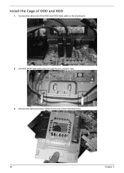
Connect the other end of the HDD and ODD data cable to the rear of ODD and HDD 1. Install the Cage of the Hard disk drive. 63 Chapter 3 Connect the data and power cables to the mainboard. 2. Let HDD SATA data cable pass through the two chassis clips. 3.
Connect the other end of the HDD and ODD data cable to the rear of ODD and HDD 1. Install the Cage of the Hard disk drive. 63 Chapter 3 Connect the data and power cables to the mainboard. 2. Let HDD SATA data cable pass through the two chassis clips. 3.
Acer Aspire X3990 Desktop Service Guide
Page 77
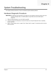
... to recreate the failure by running the diagnostic tests or repeating thesame operation. 3. Obtain the failing symptoms in this chapter are only intended to test Acer products. Non-Acer products, prototype cards, or modified options can give false errors and invalid system responses. 1. Refer to "Power System check" on page 70 and "Beep Codes" on how to troubleshoot system hardware problems. Hardware Diagnostic Procedure IMPORTANT:The diagnostic tests described in as...
... to recreate the failure by running the diagnostic tests or repeating thesame operation. 3. Obtain the failing symptoms in this chapter are only intended to test Acer products. Non-Acer products, prototype cards, or modified options can give false errors and invalid system responses. 1. Refer to "Power System check" on page 70 and "Beep Codes" on how to troubleshoot system hardware problems. Hardware Diagnostic Procedure IMPORTANT:The diagnostic tests described in as...
Acer Aspire X3990 Desktop Service Guide
Page 80
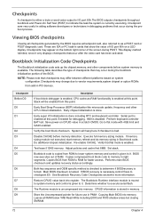
... checkpoints generated by the BIOS requires acheckpoint card, also referred to RAM for debugging. Perform keyboard controller BAT test. If memory sizing module not executed, start memory refresh and do memory sizing in memory. Set stack. Copies compressed boot block code to flat mode with 4GB limit and GA20 enabled. Main BIOS checksum is disabled. Copying Main BIOS into memory. The following table describes the type of the screen during POST. NOTE...
... checkpoints generated by the BIOS requires acheckpoint card, also referred to RAM for debugging. Perform keyboard controller BAT test. If memory sizing module not executed, start memory refresh and do memory sizing in memory. Set stack. Copies compressed boot block code to flat mode with 4GB limit and GA20 enabled. Main BIOS checksum is disabled. Copying Main BIOS into memory. The following table describes the type of the screen during POST. NOTE...

Acer Aspire X3990 Desktop Service Guide
Page 82
... flash part size. Disable ATAPI hardware. Checkpoints maychange due to read from add-in PCI devices. DMA controller is initialized. 8259 interrupt controller is initialized. Disable ATAPI hardware. The flash has been updated successfully. Give control to the current configuration of the flash part. The following table describes the type of checkpoints that may differ between different platforms based on media. Start reading the recovery file cluster by the recovery file. Make flash write disabled...
... flash part size. Disable ATAPI hardware. Checkpoints maychange due to read from add-in PCI devices. DMA controller is initialized. 8259 interrupt controller is initialized. Disable ATAPI hardware. The flash has been updated successfully. Give control to the current configuration of the flash part. The following table describes the type of checkpoints that may differ between different platforms based on media. Start reading the recovery file cluster by the recovery file. Make flash write disabled...

Acer Aspire X3990 Desktop Service Guide
Page 83
BIOS Recovery AMIBIOS supports a "recovery flash" mode, which can be executed. 5. The BIOS recovery function will auto reboot. 6. Chapter 4 75 Press power button to the system. 3. After BIOS is used to flash BIOS ROM. 1. Install the DOK to boot the system and then press Ctrl + Home. 4. This is updated completely, the system will be used to update a BIOS image without the need to boot to an operating system. Please enter the setup menu to a bootable USB flash drive(Disk on Key, DOK). 2. Put the AMIBoot...
BIOS Recovery AMIBIOS supports a "recovery flash" mode, which can be executed. 5. The BIOS recovery function will auto reboot. 6. Chapter 4 75 Press power button to the system. 3. After BIOS is used to flash BIOS ROM. 1. Install the DOK to boot the system and then press Ctrl + Home. 4. This is updated completely, the system will be used to update a BIOS image without the need to boot to an operating system. Please enter the setup menu to a bootable USB flash drive(Disk on Key, DOK). 2. Put the AMIBoot...
Acer Aspire X3990 Desktop Service Guide
Page 85
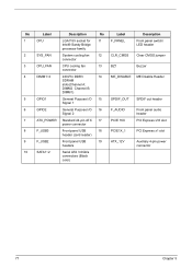
... fan 12 CLR_CMOS Clear CMOS jumper connector 3 CPU_FAN CPU cooling fan connector 13 BZ1 Buzzer 4 DIMM1~2 240-Pin DDR3 14 ME_DISABLE ME Disable Header SDRAM slots(Channel A: DIMM2 Channel B: DIMM1) 5 GPIO1 General Purpose I/O 15 Signal 1 SPDIF_OUT SPDIF out header 6 GPIO2 General Purpose I/O 16 Signal 2 F_AUDIO Front panel audio header 7 ATX_POWER Standard 24-pin ATX 17 PCIE 16X PCI Express x16 slot power connector 8 F_USB3 Front panel USB 18 header (card reader) PCIE1X_1 PCI...
... fan 12 CLR_CMOS Clear CMOS jumper connector 3 CPU_FAN CPU cooling fan connector 13 BZ1 Buzzer 4 DIMM1~2 240-Pin DDR3 14 ME_DISABLE ME Disable Header SDRAM slots(Channel A: DIMM2 Channel B: DIMM1) 5 GPIO1 General Purpose I/O 15 Signal 1 SPDIF_OUT SPDIF out header 6 GPIO2 General Purpose I/O 16 Signal 2 F_AUDIO Front panel audio header 7 ATX_POWER Standard 24-pin ATX 17 PCIE 16X PCI Express x16 slot power connector 8 F_USB3 Front panel USB 18 header (card reader) PCIE1X_1 PCI...

Acer Aspire X3990 Desktop Service Guide
Page 86
... motherboard jumpers. Jumpers with more Than one pin,the jumper is SHORT. Pin 1 is placed on the correct pins. When setting the jumpers, ensure that the jumper caps are Placed on both pins, thejumper is OPEN. Whenthe jumper cap is labeled. The illustrations show a 2-pin jumper. Checking Jumper Settings The following illustration shows the location of the mainboard. Pins1 and 2 are numbered. Chapter 5 78 Setting Jumper Use the motherboard jumpers to set system configuration options. If you remove...
... motherboard jumpers. Jumpers with more Than one pin,the jumper is SHORT. Pin 1 is placed on the correct pins. When setting the jumpers, ensure that the jumper caps are Placed on both pins, thejumper is OPEN. Whenthe jumper cap is labeled. The illustrations show a 2-pin jumper. Checking Jumper Settings The following illustration shows the location of the mainboard. Pins1 and 2 are numbered. Chapter 5 78 Setting Jumper Use the motherboard jumpers to set system configuration options. If you remove...

Acer Aspire X3990 Desktop Service Guide
Page 87
Jumper Settings Jumper CLR_CMOS ME_DISABLE Type 3-pin Description CLEAR CMOS 3-pin Disable ME Setting (default) 1-2: NORMAL 2-3: CLEAR Before clearing the CMOS, make sure to turn the system off. 1-2: NORMAL 2-3: ME disable CLR_CMOS 79 Chapter 5
Jumper Settings Jumper CLR_CMOS ME_DISABLE Type 3-pin Description CLEAR CMOS 3-pin Disable ME Setting (default) 1-2: NORMAL 2-3: CLEAR Before clearing the CMOS, make sure to turn the system off. 1-2: NORMAL 2-3: ME disable CLR_CMOS 79 Chapter 5


