Acer Aspire 5735 Hard Drive

Related Manual Pages

Similar Questions

What Is The Largest Hard Drive The Aspire 5735 Can Support?
(Posted by CaptEscal 9 years ago)


I Had To Replace The Hard Drive. The Recovery Disks I Made Wont Work. Is There
The recovery disks won't install the system on a hard drive that I had to replace
The recovery disks won't install the system on a hard drive that I had to replace
(Posted by Bobbye 11 years ago)

Acer 5735-4774 Hdd Pw Reset I Have...
The reset codes from acer, but they dont show how to input information. I got the laptop in bad cond...
The reset codes from acer, but they dont show how to input information. I got the laptop in bad cond...
(Posted by furiouswolf 12 years ago)

Second Hard Drive
Acer Aspire 8943G-9429 2.5 Hard Drive won't fit into second hard drive bay; is there a fix for this?
Acer Aspire 8943G-9429 2.5 Hard Drive won't fit into second hard drive bay; is there a fix for this?
(Posted by dbooher 12 years ago)
Related Terms
The following terms were also used when searching for Acer Aspire 5735 Hard Drive:- acer aspire 5735
- acer aspire 5735z
- aspire 5735
- aspire 5735z
- acer aspire 5735z laptop
- acer aspire 5735 laptop
- acer aspire 5735 drivers
- aspire 5735 drivers
- aspire 5735 laptop
- acer aspire 5735 4774
- acer aspire 5735 battery
- aspire 5735z laptop
- acer aspire 5735z recovery
- acer aspire 5735z battery
- acer aspire 5735 4624
- acer aspire 5735 bios
- aspire 5735 4774
- aspire 5735 4624
- aspire 5735 bios
- aspire 5735 battery
- acer aspire 5735 review
- aspire 5735z recovery
- acer aspire 5735 6694
- acer aspire 5735 keyboard
- aspire 5735 6694
- aspire 5735z battery
- aspire 5735 keyboard
- aspire 5735 fan
- aspire 5735 restore
- acer aspire5735 4774
- aspire 5735 manual
- aspire5735 drivers
- acer aspire 5735 manual
- aspire 5735 charger
- aspire 5735 review
- acer aspire 5735 motherboard
- aspire 5735 recovery disk
- aspire5735 4774
- aspire5735/5735z/5335
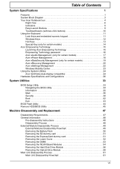
- acer aspire 5735 service manual
- acer aspire5735 4624
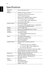
- aspire 5735 specs
- aspire 5735 video driver
- acer aspire 5735 charger
- acer aspire 5735 power cord
- acer aspire 5735 specs
- acer aspire5735 6694
- aspire 5735 motherboard
- aspire 5735 power cord
- aspire 5735 service manual
- aspire 5735 windows 7 drivers
- aspire 5735/5735z/5335 bios
- aspire 5735z manual
- aspire 5735 6285
- acer aspire 5735 4774 adapter
- acer aspire 5735 4774 battery
- acer aspire 5735 4774 drivers
- acer aspire 5735 4774 hard drive
- acer aspire 5735 4774 manual
- acer aspire 5735 4774 parts
- acer aspire 5735 ac adapter
- acer aspire 5735 battery not detected
- acer aspire 5735 boot disk
- acer aspire 5735 cmos battery location
- acer aspire 5735 disassembly
- acer aspire 5735 driver
- acer aspire 5735 drivers windows 7
- acer aspire 5735 factory reset
- acer aspire 5735 factory restore
- acer aspire 5735 factory settings download
- acer aspire 5735 fan
- acer aspire 5735 for sale
- acer aspire 5735 hard drive
- acer aspire 5735 hard drive removal
- acer aspire 5735 hard drive replacement
- acer aspire 5735 inverter
- acer aspire 5735 keyboard replacement
- acer aspire 5735 laptop battery
- acer aspire 5735 manual pdf
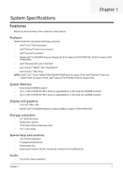
- acer aspire 5735 memory
- acer aspire 5735 memory upgrade
- acer aspire 5735 monitor driver
- acer aspire 5735 mouse button
- acer aspire 5735 notebook
- acer aspire 5735 overheating
- acer aspire 5735 overheating problem
- acer aspire 5735 parts
- acer aspire 5735 power jack
- acer aspire 5735 power socket repair
- acer aspire 5735 power supply
- acer aspire 5735 price
- acer aspire 5735 ram
- acer aspire 5735 recovery
- acer aspire 5735 recovery disk
- acer aspire 5735 replacement battery
- acer aspire 5735 reset bios
- acer aspire 5735 restore
- acer aspire 5735 restore to factory settings
- acer aspire 5735 screen
- acer aspire 5735 screen replacement
- acer aspire 5735 specifications
- acer aspire 5735 support
- acer aspire 5735 user manual
- acer aspire 5735 wifi not working
- acer aspire 5735 windows 7 x64 drivers
- acer aspire 5735 wireless driver
- acer aspire 5735 xp
- acer aspire 5735-4624
- acer aspire 5735-4774
- acer aspire 5735-6694
- acer aspire 5735z bios
- acer aspire 5735z keyboard
- acer aspire 5735z keyboard replacement
- acer aspire 5735z lcd
- acer aspire 5735z manual
- acer aspire 5735z motherboard
- acer aspire 5735z parts
- acer aspire 5735z processor
- acer aspire 5735z screen
- acer aspire 5735z screen replacement
- acer aspire 5735z service manual
- acer aspire 5735z specifications
- acer aspire5735
- acer aspire5735 notebook
- acer aspire5735-4774
- aspire 5735 12 cell battery
- aspire 5735 15.4 lcd
- aspire 5735 4774 adapter
- aspire 5735 4774 battery
- aspire 5735 4774 drivers
- aspire 5735 4774 hard drive
- aspire 5735 4774 laptop battery
- aspire 5735 4774 manual
- aspire 5735 4774 parts
- aspire 5735 4774 power adapter
- aspire 5735 ac adapter
- aspire 5735 battery life
- aspire 5735 battery not detected
- aspire 5735 bluetooth
- aspire 5735 bluetooth driver
- aspire 5735 boot disk
- aspire 5735 carte mere
- aspire 5735 cmos battery location
- aspire 5735 dc jack
- aspire 5735 dead
- aspire 5735 dim screen
- aspire 5735 disassembly
- aspire 5735 driver
- aspire 5735 drivers vista
- aspire 5735 drivers windows 7
- aspire 5735 drivers xp
- aspire 5735 factory reset
- aspire 5735 factory restore
- aspire 5735 factory settings download
- aspire 5735 for sale
- aspire 5735 hard drive
- aspire 5735 hard drive removal
- aspire 5735 hard drive replacement
- aspire 5735 inverter
- aspire 5735 keyboard replacement
- aspire 5735 laptop battery
- aspire 5735 manual pdf
- aspire 5735 memory
- aspire 5735 memory upgrade
- aspire 5735 monitor driver
- aspire 5735 monitor part
- aspire 5735 mouse button
- aspire 5735 no battery detected
- aspire 5735 notebook
- aspire 5735 overheating
- aspire 5735 overheating problem
- aspire 5735 parts
- aspire 5735 power adapter
- aspire 5735 power button problem
- aspire 5735 power jack
- aspire 5735 power socket repair
- aspire 5735 power supply
- aspire 5735 price
- aspire 5735 problems
- aspire 5735 ram
- aspire 5735 ram upgrade
- aspire 5735 recovery
- aspire 5735 repair manual
- aspire 5735 replacement battery
- aspire 5735 reset bios
- aspire 5735 restore factory settings
- aspire 5735 restore to factory settings
- aspire 5735 screen
- aspire 5735 screen replacement
- aspire 5735 skin
- aspire 5735 specifications
- aspire 5735 support
- aspire 5735 touchpad driver
- aspire 5735 troubleshooting
- aspire 5735 user manual
- aspire 5735 vista keyboard driver
- aspire 5735 wifi not working
- aspire 5735 windows 10
- aspire 5735 windows 7
- aspire 5735 windows 7 x64 drivers
- aspire 5735 windows 8
- aspire 5735 wireless driver
- aspire 5735 wont turn on
- aspire 5735 xp
- aspire 5735-4624
- aspire 5735-4774
- aspire 5735-6694
- aspire 5735/5735z/5335
- aspire 5735z bios
- aspire 5735z bluetooth
- aspire 5735z hard drive
- aspire 5735z keyboard
- aspire 5735z keyboard replacement
- aspire 5735z lcd
- aspire 5735z motherboard
- aspire 5735z parts
- aspire 5735z processor
- aspire 5735z restore
- aspire 5735z screen
- aspire 5735z screen replacement
- aspire 5735z service manual
- aspire 5735z specifications
- aspire 5735z touchpad
- aspire 5735z windows 7
- aspire5735-4774