Aspire 3690 - 5630 - 5680 User's Guide EN
Page 5
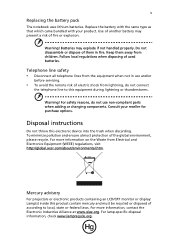
... connect the telephone line to local, state or federal laws. For lamp-specific disposal information, check www.lamprecycle.org. Do not disassemble or dispose of the global environment, please recycle. Batteries may present a risk of used batteries. Consult your product. To minimize ...pollution and ensure utmost protection of them away from Electrical and Electronics Equipment (WEEE) regulations, visit http://global.acer.com/about/environmental.htm. Use of another battery may explode if not handled properly. For more information on the Waste from ...
... connect the telephone line to local, state or federal laws. For lamp-specific disposal information, check www.lamprecycle.org. Do not disassemble or dispose of the global environment, please recycle. Batteries may present a risk of used batteries. Consult your product. To minimize ...pollution and ensure utmost protection of them away from Electrical and Electronics Equipment (WEEE) regulations, visit http://global.acer.com/about/environmental.htm. Use of another battery may explode if not handled properly. For more information on the Waste from ...

Aspire 3690 - 5630 - 5680 User's Guide EN
Page 103
... on the recorded image and does not constitute a malfunction. Nevertheless, some pixels may occasionally misfire or appear as black or red dots. Reverse engineering or disassembly is protected by Macrovision. ADVARSEL: LASERSTRÅLING VEDÅBNING SE IKKE IND I ADVERTENCIA: RADIACIÓN LÁSER INVISIBLE AL SER ABIERTO. This product...
... on the recorded image and does not constitute a malfunction. Nevertheless, some pixels may occasionally misfire or appear as black or red dots. Reverse engineering or disassembly is protected by Macrovision. ADVARSEL: LASERSTRÅLING VEDÅBNING SE IKKE IND I ADVERTENCIA: RADIACIÓN LÁSER INVISIBLE AL SER ABIERTO. This product...
Aspire 5680/5650/5630/5610/5610Z/3690 User's Guide
Page 5
... with the supplied power supply cord set , make sure that are covered by a qualified technician to restore the product to normal condition. Warning! Do not disassemble or dispose of used batteries. Refer all servicing to dangerous voltage points or other controls may expose you need to rain or water • the...
... with the supplied power supply cord set , make sure that are covered by a qualified technician to restore the product to normal condition. Warning! Do not disassemble or dispose of used batteries. Refer all servicing to dangerous voltage points or other controls may expose you need to rain or water • the...
Aspire 5680/5650/5630/5610/5610Z/3690 User's Guide
Page 114
... may occasionally misfire or appear as black or red dots. patents and other limited viewing uses only unless otherwise authorized by Macrovision. Reverse engineering or disassembly is protected by Macrovision, and is located on the recorded image and does not constitute a malfunction. EVITE EXPONERSE A LOS RAYOS. LAVATTAESSA OLET ALTTINA LASERSÅ...
... may occasionally misfire or appear as black or red dots. patents and other limited viewing uses only unless otherwise authorized by Macrovision. Reverse engineering or disassembly is protected by Macrovision, and is located on the recorded image and does not constitute a malfunction. EVITE EXPONERSE A LOS RAYOS. LAVATTAESSA OLET ALTTINA LASERSÅ...

Service Guide
Page 65
... the stripe cover, please be careful not to scrape the cover. Chapter 3 Machine Disassembly and Replacement This chapter contains step-by-step procedures on how to disassemble the notebook computer for the different components vary in size. During the disassembly process, group the screws with the corresponding components to avoid mismatch when putting...
... the stripe cover, please be careful not to scrape the cover. Chapter 3 Machine Disassembly and Replacement This chapter contains step-by-step procedures on how to disassemble the notebook computer for the different components vary in size. During the disassembly process, group the screws with the corresponding components to avoid mismatch when putting...

Service Guide
Page 66
Remove the battery pack. 58 Chapter 3 Turn off the power to the system and all power and signal cables from the system. 3. Unplug the AC adapter and all peripherals. 2. General Information Before You Begin Before proceeding with the disassembly procedure, make sure that you do the following: 1.
Remove the battery pack. 58 Chapter 3 Turn off the power to the system and all power and signal cables from the system. 3. Unplug the AC adapter and all peripherals. 2. General Information Before You Begin Before proceeding with the disassembly procedure, make sure that you do the following: 1.

Service Guide
Page 67
... assembly on bottom side C*2 upper case assembly to be removed during servicing. Disassembly Procedure Flowchart The flowchart on the succeeding page gives you a graphic representation on the entire disassembly sequence and instructs you must first remove the keyboard, then disassemble the inside assembly frame in that need to lower case assembly on upper...
... assembly on bottom side C*2 upper case assembly to be removed during servicing. Disassembly Procedure Flowchart The flowchart on the succeeding page gives you a graphic representation on the entire disassembly sequence and instructs you must first remove the keyboard, then disassemble the inside assembly frame in that need to lower case assembly on upper...
Service Guide
Page 74
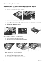
... detach the touchpad bracket from the main board. 3. Disconnect the LED board cable from the uppwer case. 66 Chapter 3 Disassembling the Upper Case Assembly 6. NOTE: Only Aspire 5650 series have media board. 9. Take out the media board cable from the lower case as shown. 5. Detach the media... Remove two screws fastening the upper case assembly to the lower case assembly. 2. Remove the screws holding the touchpad bracket. 11. Disassembling the Main Unit Separate the Main Unit Into the Upper and the Lower Case Assembly 1. Disconnect the touchpad cable from the upper case carefully...
... detach the touchpad bracket from the main board. 3. Disconnect the LED board cable from the uppwer case. 66 Chapter 3 Disassembling the Upper Case Assembly 6. NOTE: Only Aspire 5650 series have media board. 9. Take out the media board cable from the lower case as shown. 5. Detach the media... Remove two screws fastening the upper case assembly to the lower case assembly. 2. Remove the screws holding the touchpad bracket. 11. Disassembling the Main Unit Separate the Main Unit Into the Upper and the Lower Case Assembly 1. Disconnect the touchpad cable from the upper case carefully...

Service Guide
Page 75
Disassembling the Lower Case Assembly 1. Detach the modem cable from the main board then detach the modem board. 4. Remove the screw fastening the modem board. 3. Disconnect the modem board from the lower case. 5. Then disconnect the microphone cable from the upper case. Detach the touchpad from the main baord. Chapter 3 67 Disconnect the touchpad FFC. 13. Then remove the touchpad FFC from the main board. 6. Disconnect the speaker cable from the touchpad. 14. Detach the switch board from the main board. 2. 12.
Disassembling the Lower Case Assembly 1. Detach the modem cable from the main board then detach the modem board. 4. Remove the screw fastening the modem board. 3. Disconnect the modem board from the lower case. 5. Then disconnect the microphone cable from the upper case. Detach the touchpad from the main baord. Chapter 3 67 Disconnect the touchpad FFC. 13. Then remove the touchpad FFC from the main board. 6. Disconnect the speaker cable from the touchpad. 14. Detach the switch board from the main board. 2. 12.

Service Guide
Page 77
Tear off the tape fastening the LCD cable. 10. Disassembling the LCD Module 1. Remove the four screws fastening the LCD right bracket. 11. Remove the LCD right bracket. Then detach the LCD bezel from the ...
Tear off the tape fastening the LCD cable. 10. Disassembling the LCD Module 1. Remove the four screws fastening the LCD right bracket. 11. Remove the LCD right bracket. Then detach the LCD bezel from the ...

Service Guide
Page 79
Remove two screws hodling the HDD bracket on the other side. 3. Disassembling the ODD Module 1. Remove the three screws holding the optical bracket. 2. Remove another two screws fastening the HDD bracket on one side. 2. Chapter 3 71 Detach the HDD from the optical disk drive. Remove the optical bracket from the HDD bracket. Disassembling the External Modules Disassembling the HDD Module 1.
Remove two screws hodling the HDD bracket on the other side. 3. Disassembling the ODD Module 1. Remove the three screws holding the optical bracket. 2. Remove another two screws fastening the HDD bracket on one side. 2. Chapter 3 71 Detach the HDD from the optical disk drive. Remove the optical bracket from the HDD bracket. Disassembling the External Modules Disassembling the HDD Module 1.


