Aspire 5532 Battery - Acer
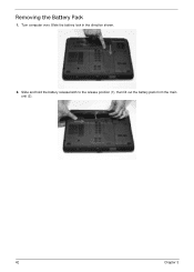
Aspire 5532 Battery
Related Manual Pages

Related Videos

Acer Aspire 5532 Battery Replacement Guide - How to Tutorial for Laptop Notebook
Duration: 1:23
Total Views: 1,737
Duration: 1:23
Total Views: 1,737
Similar Questions

Acer Aspire 5532 Laptop Battery Not Charging When Plugged In
(Posted by iziquRoni14 10 years ago)

Where Is The Cmos Battery In Acer Aspire 5532-5535 Laptop
(Posted by nullsjay 10 years ago)

How Do I Replace The Battery On My Acer 5532, Can I Order It Online,install Myse
Can I replace it myelf?
Can I replace it myelf?
(Posted by Kashu215 11 years ago)


Battery Doesn't Charge
What software in my computer allows my battery to charge? This is because I have been unable to char...
What software in my computer allows my battery to charge? This is because I have been unable to char...
(Posted by gaiusnti 12 years ago)
Related Terms
The following terms were also used when searching for Aspire 5532 Battery - Acer:- acer aspire 5532
- aspire 5532
- acer aspire 5532 laptop
- aspire 5532 laptop
- aspire5532
- aspire 5532 series
- acer aspire 5532 keyboard
- acer aspire 5532 touchpad
- aspire 5532 touchpad
- aspire 5532 keyboard
- acer aspire 5532 drivers
- aspire 5532 drivers
- acer aspire 5532 5535
- aspire 5532 5535
- aspire 5532 recovery
- aspire 5532 manual
- acer aspire 5532 memory
- acer aspire 5532 price
- acer aspire 5532 series
- acer aspire 5532 manual
- acer aspire5532 manual
- aspire 5532 webcam
- acer aspire 5532 battery
- acer aspire 5532 webcam
- acer aspire5532 bluetooth
- aspire 5532 price
- aspire 5532 battery
- aspire 5532 review
- aspire 5532 xp drivers
- aspire5532/manual
- acer aspire 5532 review
- aspire 5532 memory
- aspire 5532 support
- acer aspire 5532 charger
- acer aspire5532 5535
- aspire 5532 charger
- aspire 5532 webcam driver
- acer aspire 5532 power cord
- acer aspire 5532 specs
- acer aspire 5532 xp drivers
- acer aspire 5532 webcam driver
- aspire 5532 touchpad not working
- acer aspire 5532 reviews
- aspire 5532 reviews
- aspire 5532 specs
- aspire 5532 disassembly
- aspire 5532 recovery partition
- aspire5532 password
- acer aspire 5532 5535 screen
- acer aspire 5532 battery not charging
- acer aspire 5532 battery replacement
- acer aspire 5532 bios password
- acer aspire 5532 bios password reset
- acer aspire 5532 bios recovery
- acer aspire 5532 black screen
- acer aspire 5532 black screen fix
- acer aspire 5532 boot disk windows 7
- acer aspire 5532 cpu upgrade
- acer aspire 5532 crystal eye webcam download
- acer aspire 5532 cursor won't move
- acer aspire 5532 dead screen
- acer aspire 5532 disassembly
- acer aspire 5532 drivers windows 8
- acer aspire 5532 dvd driver
- acer aspire 5532 factory reset
- acer aspire 5532 factory restore
- acer aspire 5532 hinge cover
- acer aspire 5532 kawg0
- acer aspire 5532 kawg0 specs
- acer aspire 5532 keyboard cover
- acer aspire 5532 keyboard replacement
- acer aspire 5532 laptop battery
- acer aspire 5532 laptop for sale
- acer aspire 5532 laptop memory
- acer aspire 5532 laptop parts
- acer aspire 5532 laptop specs
- acer aspire 5532 lcd screen
- acer aspire 5532 monitor blank
- acer aspire 5532 motherboard
- acer aspire 5532 motherboard replacement
- acer aspire 5532 no display
- acer aspire 5532 not charging
- acer aspire 5532 owners manual
- acer aspire 5532 power jack
- acer aspire 5532 problems
- acer aspire 5532 processor
- acer aspire 5532 processor upgrade
- acer aspire 5532 ram
- acer aspire 5532 ram upgrade
- acer aspire 5532 recovery
- acer aspire 5532 recovery disk
- acer aspire 5532 recovery disk download
- acer aspire 5532 recovery partition
- acer aspire 5532 release date
- acer aspire 5532 repair manual
- acer aspire 5532 replacement battery
- acer aspire 5532 replacement parts
- acer aspire 5532 replacement screen
- acer aspire 5532 restore factory settings
- acer aspire 5532 screen
- acer aspire 5532 screen replacement
- acer aspire 5532 screen stays black
- acer aspire 5532 screen won't come on
- acer aspire 5532 screen wont turn on
- acer aspire 5532 series battery
- acer aspire 5532 series laptop
- acer aspire 5532 specifications
- acer aspire 5532 support
- acer aspire 5532 system recovery
- acer aspire 5532 touchpad not working
- acer aspire 5532 touchpad not working at all
- acer aspire 5532 troubleshooting
- acer aspire 5532 upgrade
- acer aspire 5532 usb ports not working
- acer aspire 5532 usb replacement
- acer aspire 5532 user manual
- acer aspire 5532 video card
- acer aspire 5532 wifi button
- acer aspire 5532 wifi switch
- acer aspire 5532 will not boot
- acer aspire 5532 wireless adapter
- acer aspire 5532 wireless card
- acer aspire 5532 wireless driver
- acer aspire 5532 wireless switch
- acer aspire 5532 won't boot
- acer aspire 5532 won't turn on
- acer aspire 5532 year
- acer aspire5532
- acer aspire5532 manual bluetooth
- acer laptop aspire5532
- aspire 5532 5535 screen
- aspire 5532 acer
- aspire 5532 acer manual
- aspire 5532 battery not charging
- aspire 5532 battery replacement
- aspire 5532 bios
- aspire 5532 bios password
- aspire 5532 bios password reset
- aspire 5532 bios recovery
- aspire 5532 bios update
- aspire 5532 black screen
- aspire 5532 black screen fix
- aspire 5532 black screen repair
- aspire 5532 bluetooth
- aspire 5532 boot disk windows 7
- aspire 5532 boot menu
- aspire 5532 card reader
- aspire 5532 charger and battery
- aspire 5532 cmos battery
- aspire 5532 cpu upgrade
- aspire 5532 crystal eye webcam download
- aspire 5532 cursor won't move
- aspire 5532 dead screen
- aspire 5532 docking station
- aspire 5532 driver
- aspire 5532 driver download
- aspire 5532 drivers for windows 7
- aspire 5532 drivers touchpad
- aspire 5532 drivers windows 7
- aspire 5532 drivers windows 8
- aspire 5532 drivers windows xp
- aspire 5532 dvd driver
- aspire 5532 factory image
- aspire 5532 factory reset
- aspire 5532 factory restore
- aspire 5532 factory-reset
- aspire 5532 graphics card
- aspire 5532 hard drive
- aspire 5532 help
- aspire 5532 hinge cover
- aspire 5532 kawg0
- aspire 5532 kawg0 specs
- aspire 5532 keyboard cover
- aspire 5532 keyboard replacement
- aspire 5532 laptop battery
- aspire 5532 laptop drivers
- aspire 5532 laptop for sale
- aspire 5532 laptop memory
- aspire 5532 laptop parts
- aspire 5532 laptop specs
- aspire 5532 lcd
- aspire 5532 lcd screen
- aspire 5532 max ram
- aspire 5532 memory capacity
- aspire 5532 memory upgrade
- aspire 5532 monitor
- aspire 5532 monitor blank
- aspire 5532 motherboard
- aspire 5532 motherboard replacement
- aspire 5532 mouse pad not working
- aspire 5532 needs usb changed
- aspire 5532 no display
- aspire 5532 no video
- aspire 5532 not charging
- aspire 5532 owners manual
- aspire 5532 parts
- aspire 5532 password lock
- aspire 5532 password removal
- aspire 5532 pics
- aspire 5532 power cord
- aspire 5532 power jack
- aspire 5532 power supply
- aspire 5532 problems
- aspire 5532 processor
- aspire 5532 processor upgrade
- aspire 5532 ram
- aspire 5532 ram 8gb
- aspire 5532 ram upgrade
- aspire 5532 recovery disc
- aspire 5532 recovery disk
- aspire 5532 recovery disk download
- aspire 5532 release date
- aspire 5532 repair manual
- aspire 5532 replacement battery
- aspire 5532 replacement keyboard
- aspire 5532 replacement parts
- aspire 5532 replacement screen
- aspire 5532 reset bios password
- aspire 5532 restore
- aspire 5532 restore factory settings
- aspire 5532 screen
- aspire 5532 screen black
- aspire 5532 screen compatible
- aspire 5532 screen replacement
- aspire 5532 screen stays black
- aspire 5532 screen won't come on
- aspire 5532 screen wont turn on
- aspire 5532 series battery
- aspire 5532 series laptop
- aspire 5532 service manual
- aspire 5532 slow run issues
- aspire 5532 specifications
- aspire 5532 specs and more
- aspire 5532 ssd
- aspire 5532 system recovery
- aspire 5532 system restore windows 7
- aspire 5532 touchpad driver
- aspire 5532 touchpad not working at all
- aspire 5532 troubleshoot
- aspire 5532 troubleshooting
- aspire 5532 upgrade
- aspire 5532 usb drivers
- aspire 5532 usb not working
- aspire 5532 usb ports
- aspire 5532 usb ports not working
- aspire 5532 usb replacement
- aspire 5532 user manual
- aspire 5532 video card
- aspire 5532 white screen and reboots
- aspire 5532 wifi button
- aspire 5532 wifi switch
- aspire 5532 will not boot
- aspire 5532 windows 10
- aspire 5532 wireless adapter
- aspire 5532 wireless card
- aspire 5532 wireless driver
- aspire 5532 wireless drivers
- aspire 5532 wireless switch
- aspire 5532 won't boot
- aspire 5532 won't turn on
- aspire 5532 year
- aspire 5532-5535
- aspire5532 laptop
- aspire5532 series