Quick Start Guide
Page 7
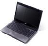
...), displays computer output (configuration may vary by model). 3 HDD indicator Indicates when the hard disk drive is closed up. Battery indicator1 Indicates the computer's battery status. 1. Fully charged: The light shows blue when in AC mode. 8 Click buttons (left The left and right ...model purchased. The front panel indicators are visible even when the computer cover is active. Charging: The light shows amber when the battery is charging. 2. Communication indicator Indicates the computer's wireless connectivity device status. 4 Power button Turns the computer on and off....
...), displays computer output (configuration may vary by model). 3 HDD indicator Indicates when the hard disk drive is closed up. Battery indicator1 Indicates the computer's battery status. 1. Fully charged: The light shows blue when in AC mode. 8 Click buttons (left The left and right ...model purchased. The front panel indicators are visible even when the computer cover is active. Charging: The light shows amber when the battery is charging. 2. Communication indicator Indicates the computer's wireless connectivity device status. 4 Power button Turns the computer on and off....
Quick Start Guide
Page 11
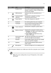
... with screws). 4 Memory compartment Houses the computer's main memory. 5 Ventilation slots and Enable the computer to 80% English 9 Base view 1 2 6 5 3 4 # Icon Item 1 Battery bay 2 Battery lock Description Houses the computer's battery pack. Environment • Temperature: • Operating: 5 °C to 35 °C • Non-operating: -20 °C to 65 °C • Humidity (non-condensing... 80% • Non-operating: 20% to stay cool, even cooling fan after prolonged use. Note: Do not cover or obstruct the opening of the fan. 6 Battery release latch Releases the...
... with screws). 4 Memory compartment Houses the computer's main memory. 5 Ventilation slots and Enable the computer to 80% English 9 Base view 1 2 6 5 3 4 # Icon Item 1 Battery bay 2 Battery lock Description Houses the computer's battery pack. Environment • Temperature: • Operating: 5 °C to 35 °C • Non-operating: -20 °C to 65 °C • Humidity (non-condensing... 80% • Non-operating: 20% to stay cool, even cooling fan after prolonged use. Note: Do not cover or obstruct the opening of the fan. 6 Battery release latch Releases the...
Service Guide
Page 3
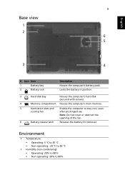
Remove the battery pack. Observe the order of the sequence to avoid damage to the system and all power and signal cables from the system. 3. Main Screw List ...
Remove the battery pack. Observe the order of the sequence to avoid damage to the system and all power and signal cables from the system. 3. Main Screw List ...

Service Guide
Page 5
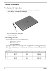
Turn base unit over. 2. Note: Battery has been highlighted with the yellow circle as above image shows. Removing the Battery Pack 1. Slide the battery release latch to the release position to the unlock position. 3. Please detach the battery and follow the local regulations for disposal. 30 Chapter 3 Slide the battery lock/unlock latch to pop out the battery pack, then remove the battery pack from the main unit.
Turn base unit over. 2. Note: Battery has been highlighted with the yellow circle as above image shows. Removing the Battery Pack 1. Slide the battery release latch to the release position to the unlock position. 3. Please detach the battery and follow the local regulations for disposal. 30 Chapter 3 Slide the battery lock/unlock latch to pop out the battery pack, then remove the battery pack from the main unit.
Service Guide
Page 7
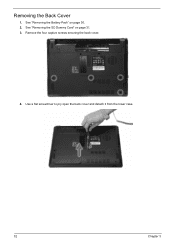
Removing the Back Cover 1. Remove the four captive screws securing the back cover. 4. Use a flat screwdriver to pry open the back cover and detach it from the lower case. 32 Chapter 3 See "Removing the SD Dummy Card" on page 30. 2. See "Removing the Battery Pack" on page 31. 3.
Removing the Back Cover 1. Remove the four captive screws securing the back cover. 4. Use a flat screwdriver to pry open the back cover and detach it from the lower case. 32 Chapter 3 See "Removing the SD Dummy Card" on page 30. 2. See "Removing the Battery Pack" on page 31. 3.
Service Guide
Page 8
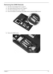
Removing the DIMM Modules 1. Remove the DIMM modules. Chapter 3 33 See "Removing the Battery Pack" on both sides of the DIMM socket to release the DIMM modules. 5. Push out the latches on page 30. 2. See "Removing the Back Cover" on page 31. 3. See "Removing the SD Dummy Card" on page 32. 4.
Removing the DIMM Modules 1. Remove the DIMM modules. Chapter 3 33 See "Removing the Battery Pack" on both sides of the DIMM socket to release the DIMM modules. 5. Push out the latches on page 30. 2. See "Removing the Back Cover" on page 31. 3. See "Removing the SD Dummy Card" on page 32. 4.
Service Guide
Page 9
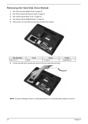
Removing the Hard Disk Drive Module 1. See "Removing the SD Dummy Card" on page 33 5. Remove the one screw (B) securing the hard disk drive module. See "Removing the DIMM Modules" on page 31. 3. Size (Quantity) M2 x L3 (1) Black Color Torque 1.6 kgf-cm 6. See "Removing the Back Cover" on page 30. 2. Lift the hard disk drive module and remove it . 34 Chapter 3 See "Removing the Battery Pack" on page 32. 4. Part No. 86.00F80.723 NOTE: To prevent damage to device, avoid pressing down on it or placing heavy objects on top of it from the hard disk drive bay.
Removing the Hard Disk Drive Module 1. See "Removing the SD Dummy Card" on page 33 5. Remove the one screw (B) securing the hard disk drive module. See "Removing the DIMM Modules" on page 31. 3. Size (Quantity) M2 x L3 (1) Black Color Torque 1.6 kgf-cm 6. See "Removing the Back Cover" on page 30. 2. Lift the hard disk drive module and remove it . 34 Chapter 3 See "Removing the Battery Pack" on page 32. 4. Part No. 86.00F80.723 NOTE: To prevent damage to device, avoid pressing down on it or placing heavy objects on top of it from the hard disk drive bay.
Service Guide
Page 11
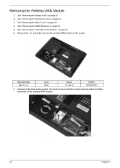
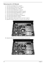
... Card" on page 34. 6. See "Removing the Hard Disk Drive Module" on page 31. 3. See "Removing the DIMM Modules" on page 30. 2. See "Removing the Battery Pack" on page 33. 5. Disconnect the blue antenna cable from AUX connector and the yellow antenna cable from Main connector on page 32. 4. Remove the...
... Card" on page 34. 6. See "Removing the Hard Disk Drive Module" on page 31. 3. See "Removing the DIMM Modules" on page 30. 2. See "Removing the Battery Pack" on page 33. 5. Disconnect the blue antenna cable from AUX connector and the yellow antenna cable from Main connector on page 32. 4. Remove the...

Service Guide
Page 12
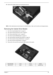
See "Removing the SD Dummy Card" on page 33. 5. Remove the label sticker from its connector. See "Removing the DIMM Modules" on page 31. 3. See "Removing the Hard Disk Drive Module" on page 36. 7. See "Removing the Wireless WAN Module" on page 34. 6. Remove the wireless WAN module from the WLAN module. NOTE: When attaching the antenna back to the wireless WAN module, make sure the cable are arranged properly. Removing the WLAN Module 1. Chapter 3 37 See "Removing the Back Cover" on page 30. 2. 8. See "Removing the Battery Pack" on page 32. 4.
See "Removing the SD Dummy Card" on page 33. 5. Remove the label sticker from its connector. See "Removing the DIMM Modules" on page 31. 3. See "Removing the Hard Disk Drive Module" on page 36. 7. See "Removing the Wireless WAN Module" on page 34. 6. Remove the wireless WAN module from the WLAN module. NOTE: When attaching the antenna back to the wireless WAN module, make sure the cable are arranged properly. Removing the WLAN Module 1. Chapter 3 37 See "Removing the Back Cover" on page 30. 2. 8. See "Removing the Battery Pack" on page 32. 4.
Service Guide
Page 14
... Module" on page 33. 5. See "Removing the DIMM Modules" on page 36. 7. See "Removing the Hard Disk Drive Module" on page 30. 2. See "Removing the Battery Pack" on page 34. 6. Remove the one screw (E) securing the ODD module to the WLAN module, make sure the cable are arranged properly. Remove the...
... Module" on page 33. 5. See "Removing the DIMM Modules" on page 36. 7. See "Removing the Hard Disk Drive Module" on page 30. 2. See "Removing the Battery Pack" on page 34. 6. Remove the one screw (E) securing the ODD module to the WLAN module, make sure the cable are arranged properly. Remove the...
Service Guide
Page 18
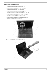
See "Removing the Battery Pack" on page 33. 5. See "Removing the DIMM Modules" on page 30. 2. See "Removing the WLAN Module" on the touchpad area. Turn the keyboard over on page 37. 8. See "Removing the SD Dummy Card" on page 32. 4. See "Removing the Back Cover" on page 31. 3. Release the keyboard from the latches. 10. See "Removing the Hard Disk Drive Module" on page 39. 9. Chapter 3 43 See "Removing the Optical Drive Module" on page 34. 6. See "Removing the Wireless WAN Module" on page 36. 7. Removing the Keyboard 1.
See "Removing the Battery Pack" on page 33. 5. See "Removing the DIMM Modules" on page 30. 2. See "Removing the WLAN Module" on the touchpad area. Turn the keyboard over on page 37. 8. See "Removing the SD Dummy Card" on page 32. 4. See "Removing the Back Cover" on page 31. 3. Release the keyboard from the latches. 10. See "Removing the Hard Disk Drive Module" on page 39. 9. Chapter 3 43 See "Removing the Optical Drive Module" on page 34. 6. See "Removing the Wireless WAN Module" on page 36. 7. Removing the Keyboard 1.
Service Guide
Page 19
... the Keyboard" on the main board and detach the keyboard. Disconnect the keyboard cable from its connector (KB1) on page 43. 10. See "Removing the Battery Pack" on page 36. 7. See "Removing the Wireless WAN Module" on page 30. 2.
... the Keyboard" on the main board and detach the keyboard. Disconnect the keyboard cable from its connector (KB1) on page 43. 10. See "Removing the Battery Pack" on page 36. 7. See "Removing the Wireless WAN Module" on page 30. 2.
Service Guide
Page 23
... WLAN Module" on page 43. 10. See "Removing the Keyboard" on page 37. 8. See "Removing the Optical Drive Module" on page 30. 2. See "Removing the Battery Pack" on page 39. 9. See "Removing the SD Dummy Card" on page 34. 6. See "Removing the Hard Disk Drive Module" on page 31. 3.
... WLAN Module" on page 43. 10. See "Removing the Keyboard" on page 37. 8. See "Removing the Optical Drive Module" on page 30. 2. See "Removing the Battery Pack" on page 39. 9. See "Removing the SD Dummy Card" on page 34. 6. See "Removing the Hard Disk Drive Module" on page 31. 3.
Service Guide
Page 26
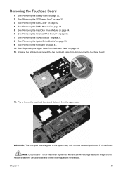
... local regulations for disposal. See "Removing the Hard Disk Drive Module" on page 33. 5. See "Removing the DIMM Modules" on page 34. 6. See "Removing the Battery Pack" on page 31. 3. See "Removing the SD Dummy Card" on page 30. 2. Release the latch and disconnect the the touchpad cable from its connector...
... local regulations for disposal. See "Removing the Hard Disk Drive Module" on page 33. 5. See "Removing the DIMM Modules" on page 34. 6. See "Removing the Battery Pack" on page 31. 3. See "Removing the SD Dummy Card" on page 30. 2. Release the latch and disconnect the the touchpad cable from its connector...
Service Guide
Page 27
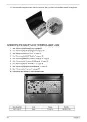
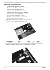
... page 32. 4. See "Removing the WLAN Module" on page 44. 11. See "Separating the Upper Case from the power board. 52 Chapter 3 See "Removing the Battery Pack" on page 39. 9. Release the latch and disconnect the the power cable from the Lower Case" on page 37. 8. Removing the Power Board 1. See...
... page 32. 4. See "Removing the WLAN Module" on page 44. 11. See "Separating the Upper Case from the power board. 52 Chapter 3 See "Removing the Battery Pack" on page 39. 9. Release the latch and disconnect the the power cable from the Lower Case" on page 37. 8. Removing the Power Board 1. See...
Service Guide
Page 28
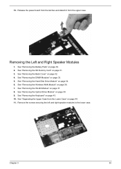
... screws securing the left and right speaker modules to the lower case. See "Removing the Hard Disk Drive Module" on page 37. 8. See "Removing the Battery Pack" on page 44. 11. See "Separating the Upper Case from the upper case. 13. See "Removing the Optical Drive Module" on page 33. 5. Release...
... screws securing the left and right speaker modules to the lower case. See "Removing the Hard Disk Drive Module" on page 37. 8. See "Removing the Battery Pack" on page 44. 11. See "Separating the Upper Case from the upper case. 13. See "Removing the Optical Drive Module" on page 33. 5. Release...
Service Guide
Page 29
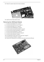
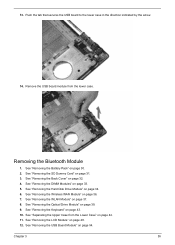
... from the tapes and lataches. 13. Release the speaker cables from its connectors on page 44. 11. Removing the USB Board Module 1. See "Removing the Battery Pack" on page 33. 5. See "Removing the DIMM Modules" on page 30. 2. See "Removing the Optical Drive Module" on page 36. 7. See "Removing the Wireless...
... from the tapes and lataches. 13. Release the speaker cables from its connectors on page 44. 11. Removing the USB Board Module 1. See "Removing the Battery Pack" on page 33. 5. See "Removing the DIMM Modules" on page 30. 2. See "Removing the Optical Drive Module" on page 36. 7. See "Removing the Wireless...
Service Guide
Page 30
... Module" on page 54. See "Removing the USB Board Module" on page 39. 9. See "Removing the Wireless WAN Module" on page 30. 2. See "Removing the Battery Pack" on page 36. 7. See "Removing the Back Cover" on page 33. 5. See "Removing the DIMM Modules" on page 32. 4. Remove the USB board module...
... Module" on page 54. See "Removing the USB Board Module" on page 39. 9. See "Removing the Wireless WAN Module" on page 30. 2. See "Removing the Battery Pack" on page 36. 7. See "Removing the Back Cover" on page 33. 5. See "Removing the DIMM Modules" on page 32. 4. Remove the USB board module...
Service Guide
Page 32
... "Removing the LCD Module" on page 39. 9. Size (Quantity) M2 x L3 (1) Color Black Torque 1.6 kgf-cm Part No. 86.00F80.723 Note: RTC battery has been highlighted with the yellow rectangle as shown in place. See "Removing the Optical Drive Module" on page 48. 12. See "Separating the Upper...See "Removing the Keyboard" on page 31. 3. Chapter 3 57 See "Removing the SD Dummy Card" on page 43. 10. Please detach the RTC battery and follow local regulations for disposal. Please detach the Circuit boards and follow local regulations for disposal. See "Removing the...
... "Removing the LCD Module" on page 39. 9. Size (Quantity) M2 x L3 (1) Color Black Torque 1.6 kgf-cm Part No. 86.00F80.723 Note: RTC battery has been highlighted with the yellow rectangle as shown in place. See "Removing the Optical Drive Module" on page 48. 12. See "Separating the Upper...See "Removing the Keyboard" on page 31. 3. Chapter 3 57 See "Removing the SD Dummy Card" on page 43. 10. Please detach the RTC battery and follow local regulations for disposal. Please detach the Circuit boards and follow local regulations for disposal. See "Removing the...
Service Guide
Page 33
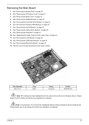
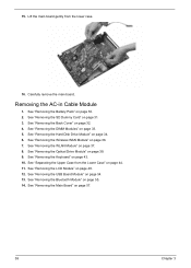
Lift the main board gently from the Lower Case" on page 55. 14. See "Removing the Battery Pack" on page 43. 10. See "Removing the Keyboard" on page 30. 2. See "Removing the USB Board Module" on page 33. 5. Removing the AC-in ...
Lift the main board gently from the Lower Case" on page 55. 14. See "Removing the Battery Pack" on page 43. 10. See "Removing the Keyboard" on page 30. 2. See "Removing the USB Board Module" on page 33. 5. Removing the AC-in ...


