Quick Start Guide
Page 5
... new computer. The Quick Guide introduces you use Adobe Reader, access the Help and Support menu. In addition it : 1 Click on Start > All Programs > AcerSystem. 2 Click on such subjects as using the keyboard and audio, etc. Follow the instructions on how to all models in certain models of your mobile computing needs. Such instances are only contained in the Aspire product series. Your guides To help you for making an Acer notebook...
... new computer. The Quick Guide introduces you use Adobe Reader, access the Help and Support menu. In addition it : 1 Click on Start > All Programs > AcerSystem. 2 Click on such subjects as using the keyboard and audio, etc. Follow the instructions on how to all models in certain models of your mobile computing needs. Such instances are only contained in the Aspire product series. Your guides To help you for making an Acer notebook...
Quick Start Guide
Page 7
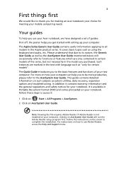
... Display (LCD), displays computer output (configuration may vary by model). 3 HDD indicator Indicates when the hard disk drive is closed up. The front panel indicators are visible even when the computer cover is active. Battery indicator1 Indicates the computer's battery status. 1. Communication indicator Indicates the computer's wireless connectivity device status. 4 Power button Turns the computer on the model purchased. Charging: The light shows amber when the battery is charging. 2. Note: The exact configuration of your PC depends on and off. 5 Keyboard For entering...
... Display (LCD), displays computer output (configuration may vary by model). 3 HDD indicator Indicates when the hard disk drive is closed up. The front panel indicators are visible even when the computer cover is active. Battery indicator1 Indicates the computer's battery status. 1. Communication indicator Indicates the computer's wireless connectivity device status. 4 Power button Turns the computer on the model purchased. Charging: The light shows amber when the battery is charging. 2. Note: The exact configuration of your PC depends on and off. 5 Keyboard For entering...

Quick Start Guide
Page 8
Hotkey + + Icon Function Description Communication Enables / disables the computer's key communication devices. (Communication devices may vary by configuration.) Sleep Puts the computer in the hotkey combination. Turns the display screen backlight off Switches display output between the display screen, external monitor (if connected) and both. Turns the speakers on and off. + NumLk Num Lock + Scr Lk Scroll Lock + < > Brightness up Turns the embedded numeric keypad on , the screen moves one line up or down when you press the...
Hotkey + + Icon Function Description Communication Enables / disables the computer's key communication devices. (Communication devices may vary by configuration.) Sleep Puts the computer in the hotkey combination. Turns the display screen backlight off Switches display output between the display screen, external monitor (if connected) and both. Turns the speakers on and off. + NumLk Num Lock + Scr Lk Scroll Lock + < > Brightness up Turns the embedded numeric keypad on , the screen moves one line up or down when you press the...
Quick Start Guide
Page 9
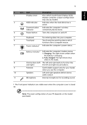
...RJ-45) Connects to remove/install the card. Connects to USB 2.0 devices (e.g., USB mouse, USB camera). port based network. HDMI port USB 2.0 port Supports high definition digital video connections. English 7 Closed front view 1 # Icon 1 Item Description Multi-in jack Description Connects to an AC adapter. Connect to a display device (e.g., external monitor, LCD projector). Left view # Icon 1 2 3 4 5 6 12 3 456 Item DC-in -1 card reader Accepts Secure Digital (SD), MultiMediaCard (MMC), Memory Stick (MS), Memory Stick PRO (MS PRO), xD-Picture Card (xD). Only...
...RJ-45) Connects to remove/install the card. Connects to USB 2.0 devices (e.g., USB mouse, USB camera). port based network. HDMI port USB 2.0 port Supports high definition digital video connections. English 7 Closed front view 1 # Icon 1 Item Description Multi-in jack Description Connects to an AC adapter. Connect to a display device (e.g., external monitor, LCD projector). Left view # Icon 1 2 3 4 5 6 12 3 456 Item DC-in -1 card reader Accepts Secure Digital (SD), MultiMediaCard (MMC), Memory Stick (MS), Memory Stick PRO (MS PRO), xD-Picture Card (xD). Only...
Quick Start Guide
Page 11
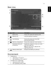
...'s main memory. 5 Ventilation slots and Enable the computer to 80% Environment • Temperature: • Operating: 5 °C to 35 °C • Non-operating: -20 °C to 65 °C • Humidity (non-condensing): • Operating: 20% to 80% • Non-operating: 20% to stay cool, even cooling fan after prolonged use. Note: Do not cover or obstruct the opening of the fan. 6 Battery release latch...
...'s main memory. 5 Ventilation slots and Enable the computer to 80% Environment • Temperature: • Operating: 5 °C to 35 °C • Non-operating: -20 °C to 65 °C • Humidity (non-condensing): • Operating: 20% to 80% • Non-operating: 20% to stay cool, even cooling fan after prolonged use. Note: Do not cover or obstruct the opening of the fan. 6 Battery release latch...
Service Guide
Page 11
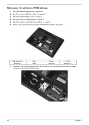
... 7. See "Removing the Battery Pack" on page 32. 4. Remove the one screw (B) securing the wireless WAN module to the system. See "Removing the SD Dummy Card" on the wireless WAN module. 36 Chapter 3 Disconnect the blue antenna cable from AUX connector and the yellow antenna cable from Main connector on page 31. 3. See "Removing the DIMM Modules" on page 34. 6. See "Removing the Hard Disk Drive Module" on...
... 7. See "Removing the Battery Pack" on page 32. 4. Remove the one screw (B) securing the wireless WAN module to the system. See "Removing the SD Dummy Card" on the wireless WAN module. 36 Chapter 3 Disconnect the blue antenna cable from AUX connector and the yellow antenna cable from Main connector on page 31. 3. See "Removing the DIMM Modules" on page 34. 6. See "Removing the Hard Disk Drive Module" on...
Service Guide
Page 18
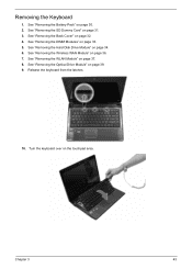
See "Removing the SD Dummy Card" on page 34. 6. See "Removing the Hard Disk Drive Module" on page 31. 3. Turn the keyboard over on page 39. 9. Release the keyboard from the latches. 10. See "Removing the Optical Drive Module" on the touchpad area. See "Removing the Wireless WAN Module" on page 37. 8. See "Removing the WLAN Module" on page 36. 7. Chapter 3 43 See "Removing the Back Cover" on page 33. 5. See "Removing the DIMM Modules" on page 32. 4. See "Removing the Battery Pack" on page 30. 2. Removing the Keyboard 1.
See "Removing the SD Dummy Card" on page 34. 6. See "Removing the Hard Disk Drive Module" on page 31. 3. Turn the keyboard over on page 39. 9. Release the keyboard from the latches. 10. See "Removing the Optical Drive Module" on the touchpad area. See "Removing the Wireless WAN Module" on page 37. 8. See "Removing the WLAN Module" on page 36. 7. Chapter 3 43 See "Removing the Back Cover" on page 33. 5. See "Removing the DIMM Modules" on page 32. 4. See "Removing the Battery Pack" on page 30. 2. Removing the Keyboard 1.
Service Guide
Page 19
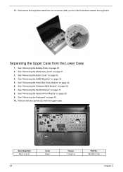
See "Removing the Hard Disk Drive Module" on the main board and detach the keyboard. 11. Disconnect the keyboard cable from its connector (KB1) on page 34. 6. See "Removing the Optical Drive Module" on page 30. 2. See "Removing the Battery Pack" on page 39. 9. See "Removing the Back Cover" on page 37. 8. Separating the Upper Case from the upper case. See "Removing the WLAN Module" on page 32. 4. Remove the...
See "Removing the Hard Disk Drive Module" on the main board and detach the keyboard. 11. Disconnect the keyboard cable from its connector (KB1) on page 34. 6. See "Removing the Optical Drive Module" on page 30. 2. See "Removing the Battery Pack" on page 39. 9. See "Removing the Back Cover" on page 37. 8. Separating the Upper Case from the upper case. See "Removing the WLAN Module" on page 32. 4. Remove the...
Service Guide
Page 23
... "Removing the Hard Disk Drive Module" on page 39. 9. See "Removing the Optical Drive Module" on page 34. 6. See "Removing the DIMM Modules" on page 43. 10. See "Removing the Keyboard" on page 33. 5. Detach the microphone cable from its connector and tape on page 37. 8. See "Removing the SD Dummy Card" on the main board. 12. See "Removing the WLAN Module" on the main board. 48 Chapter 3 Detach the LCD cable...
... "Removing the Hard Disk Drive Module" on page 39. 9. See "Removing the Optical Drive Module" on page 34. 6. See "Removing the DIMM Modules" on page 43. 10. See "Removing the Keyboard" on page 33. 5. Detach the microphone cable from its connector and tape on page 37. 8. See "Removing the SD Dummy Card" on the main board. 12. See "Removing the WLAN Module" on the main board. 48 Chapter 3 Detach the LCD cable...
Service Guide
Page 26
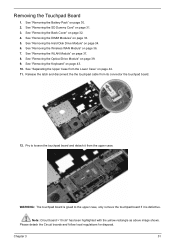
... upper case. Note: Circuit board >10 cm² has been highlighted with the yellow rectangle as above image shows. See "Removing the Hard Disk Drive Module" on page 31. 3. See "Removing the Keyboard" on page 33. 5. See "Removing the DIMM Modules" on page 43. 10. Chapter 3 51 Removing the Touchpad Board 1. See "Removing the Battery Pack" on page 36. 7. See "Removing the Wireless WAN Module" on page 30. 2.
... upper case. Note: Circuit board >10 cm² has been highlighted with the yellow rectangle as above image shows. See "Removing the Hard Disk Drive Module" on page 31. 3. See "Removing the Keyboard" on page 33. 5. See "Removing the DIMM Modules" on page 43. 10. Chapter 3 51 Removing the Touchpad Board 1. See "Removing the Battery Pack" on page 36. 7. See "Removing the Wireless WAN Module" on page 30. 2.
Service Guide
Page 27
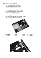
... Hard Disk Drive Module" on page 33. 5. Release the latch and disconnect the the power cable from the Lower Case" on page 37. 8. See "Removing the Wireless WAN Module" on page 39. 9. See "Removing the Optical Drive Module" on page 36. 7. Size (Quantity) M2 x L3 (1) Color Black Torque 1. 6 kgf-cm Part No. 86.00F80.723 12. See "Removing the Back Cover" on page 30. 2. See "Removing the Battery...
... Hard Disk Drive Module" on page 33. 5. Release the latch and disconnect the the power cable from the Lower Case" on page 37. 8. See "Removing the Wireless WAN Module" on page 39. 9. See "Removing the Optical Drive Module" on page 36. 7. Size (Quantity) M2 x L3 (1) Color Black Torque 1. 6 kgf-cm Part No. 86.00F80.723 12. See "Removing the Back Cover" on page 30. 2. See "Removing the Battery...
Service Guide
Page 28
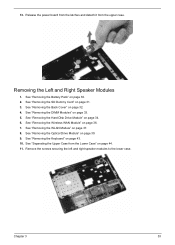
... Battery Pack" on page 37. 8. See "Removing the WLAN Module" on page 30. 2. Remove the screws securing the left and right speaker modules to the lower case. Chapter 3 53 See "Removing the Wireless WAN Module" on page 39. 9. See "Removing the Optical Drive Module" on page 36. 7. See "Removing the Keyboard" on page 34. 6. See "Removing the Hard Disk Drive Module" on page 43. 10. See "Removing the Back Cover...
... Battery Pack" on page 37. 8. See "Removing the WLAN Module" on page 30. 2. Remove the screws securing the left and right speaker modules to the lower case. Chapter 3 53 See "Removing the Wireless WAN Module" on page 39. 9. See "Removing the Optical Drive Module" on page 36. 7. See "Removing the Keyboard" on page 34. 6. See "Removing the Hard Disk Drive Module" on page 43. 10. See "Removing the Back Cover...
Service Guide
Page 29
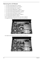
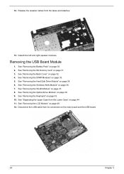
... "Removing the Back Cover" on page 34. 6. See "Removing the Hard Disk Drive Module" on page 32. 4. See "Removing the WLAN Module" on page 36. 7. See "Removing the Wireless WAN Module" on page 37. 8. Disconnect the USB cable from its connectors on page 44. 11. See "Separating the Upper Case from the tapes and lataches. 13. See "Removing the Keyboard" on page 48. 12. See "Removing the LCD Module...
... "Removing the Back Cover" on page 34. 6. See "Removing the Hard Disk Drive Module" on page 32. 4. See "Removing the WLAN Module" on page 36. 7. See "Removing the Wireless WAN Module" on page 37. 8. Disconnect the USB cable from its connectors on page 44. 11. See "Separating the Upper Case from the tapes and lataches. 13. See "Removing the Keyboard" on page 48. 12. See "Removing the LCD Module...
Service Guide
Page 30
See "Removing the Wireless WAN Module" on page 43. 10. See "Removing the Keyboard" on page 36. 7. See "Removing the DIMM Modules" on page 34. 6. See "Removing the Hard Disk Drive Module" on page 33. 5. See "Removing the Optical Drive Module" on page 30. 2. See "Removing the Battery Pack" on page 39. 9. See "Removing the WLAN Module" on page 48. 12. See "Removing the LCD Module" on page 37. 8. Remove the USB board module from the Lower...
See "Removing the Wireless WAN Module" on page 43. 10. See "Removing the Keyboard" on page 36. 7. See "Removing the DIMM Modules" on page 34. 6. See "Removing the Hard Disk Drive Module" on page 33. 5. See "Removing the Optical Drive Module" on page 30. 2. See "Removing the Battery Pack" on page 39. 9. See "Removing the WLAN Module" on page 48. 12. See "Removing the LCD Module" on page 37. 8. Remove the USB board module from the Lower...
Service Guide
Page 32
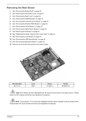
... "Removing the Keyboard" on page 39. 9. See "Removing the Hard Disk Drive Module" on page 44. 11. Note: Circuit boards >10 cm² has been highlighted with the yellow circle as above . See "Separating the Upper Case from the Lower Case" on page 34. 6. Size (Quantity) M2 x L3 (1) Color Black Torque 1.6 kgf-cm Part No. 86.00F80.723 Note: RTC battery...
... "Removing the Keyboard" on page 39. 9. See "Removing the Hard Disk Drive Module" on page 44. 11. Note: Circuit boards >10 cm² has been highlighted with the yellow circle as above . See "Separating the Upper Case from the Lower Case" on page 34. 6. Size (Quantity) M2 x L3 (1) Color Black Torque 1.6 kgf-cm Part No. 86.00F80.723 Note: RTC battery...
Service Guide
Page 33
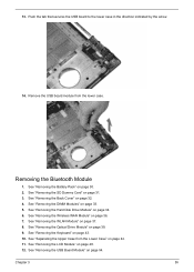
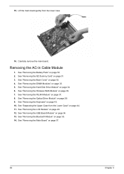
... page 33. 5. Carefully remove the main board. See "Removing the Wireless WAN Module" on page 55. 14. See "Separating the Upper Case from the lower case. 16. See "Removing the Bluetooth Module" on page 36. 7. See "Removing the Hard Disk Drive Module" on page 48. 12. See "Removing the LCD Module" on page 34. 6. See "Removing the SD Dummy Card" on page 44. 11. 15. Removing the AC-in Cable Module 1.
... page 33. 5. Carefully remove the main board. See "Removing the Wireless WAN Module" on page 55. 14. See "Separating the Upper Case from the lower case. 16. See "Removing the Bluetooth Module" on page 36. 7. See "Removing the Hard Disk Drive Module" on page 48. 12. See "Removing the LCD Module" on page 34. 6. See "Removing the SD Dummy Card" on page 44. 11. 15. Removing the AC-in Cable Module 1.
Service Guide
Page 34
See "Removing the SD Dummy Card" on page 36. 7. See "Removing the Wireless WAN Module" on page 31. 3. See "Removing the DIMM Modules" on page 34. 6. See "Removing the Hard Disk Drive Module" on page 33. 5. See "Removing the USB Board Module" on page 32. 4. See "Removing the Back Cover" on page 54. 13. See "Removing the WLAN Module" on page 55. See "Removing the Bluetooth Module" on page 37. 8. For this section, we...
See "Removing the SD Dummy Card" on page 36. 7. See "Removing the Wireless WAN Module" on page 31. 3. See "Removing the DIMM Modules" on page 34. 6. See "Removing the Hard Disk Drive Module" on page 33. 5. See "Removing the USB Board Module" on page 32. 4. See "Removing the Back Cover" on page 54. 13. See "Removing the WLAN Module" on page 55. See "Removing the Bluetooth Module" on page 37. 8. For this section, we...
Service Guide
Page 36
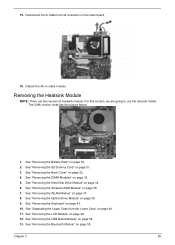
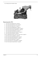
... Dummy Card" on page 55. 14. See "Removing the Bluetooth Module" on page 31. 3. 18. See "Removing the Hard Disk Drive Module" on page 33. 5. Carefully lift up the heatsink module. See "Removing the DIMM Modules" on page 34. 6. See "Removing the AC-in Cable Module" on page 43. 10. See "Removing the Keyboard" on page 58. 16. Removing the CPU 1. See "Removing the USB Board Module" on page 37. 8. See "Removing the WLAN Module...
... Dummy Card" on page 55. 14. See "Removing the Bluetooth Module" on page 31. 3. 18. See "Removing the Hard Disk Drive Module" on page 33. 5. Carefully lift up the heatsink module. See "Removing the DIMM Modules" on page 34. 6. See "Removing the AC-in Cable Module" on page 43. 10. See "Removing the Keyboard" on page 58. 16. Removing the CPU 1. See "Removing the USB Board Module" on page 37. 8. See "Removing the WLAN Module...
Service Guide
Page 40
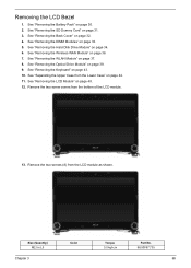
.... 6. See "Removing the Hard Disk Drive Module" on page 33. 5. See "Removing the Wireless WAN Module" on page 43. 10. Remove the two screws (A) from the bottom of the LCD module. 13. Size (Quantity) M2.5 x L5 Chapter 3 Color Torque 3.0 kgf-cm Part No. 86.00F87.735 65 See "Removing the Keyboard" on page 36. 7. Remove the two screw covers from the LCD module as shown. See "Removing the LCD Module" on...
.... 6. See "Removing the Hard Disk Drive Module" on page 33. 5. See "Removing the Wireless WAN Module" on page 43. 10. Remove the two screws (A) from the bottom of the LCD module. 13. Size (Quantity) M2.5 x L5 Chapter 3 Color Torque 3.0 kgf-cm Part No. 86.00F87.735 65 See "Removing the Keyboard" on page 36. 7. Remove the two screw covers from the LCD module as shown. See "Removing the LCD Module" on...
Service Guide
Page 42
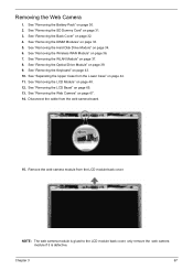
... Dummy Card" on page 39. 9. See "Removing the Optical Drive Module" on page 31. 3. See "Removing the Web Camera" on page 30. 2. Removing the Web Camera 1. See "Removing the Battery Pack" on page 67. 14. See "Removing the Hard Disk Drive Module" on page 36. 7. See "Removing the Wireless WAN Module" on page 34. 6. See "Separating the Upper Case from the web camera board. 15. Remove the web camera module from the LCD module back cover.
... Dummy Card" on page 39. 9. See "Removing the Optical Drive Module" on page 31. 3. See "Removing the Web Camera" on page 30. 2. Removing the Web Camera 1. See "Removing the Battery Pack" on page 67. 14. See "Removing the Hard Disk Drive Module" on page 36. 7. See "Removing the Wireless WAN Module" on page 34. 6. See "Separating the Upper Case from the web camera board. 15. Remove the web camera module from the LCD module back cover.


