Quick Start Guide
Page 5
...program first. If Adobe Reader is available in the Aspire product series. For instructions on the screen to complete the installation. The Aspire Series Generic User Guide contains useful information applying to...It is not installed on how your notebook. It covers basic topics such as using the keyboard and audio, etc. This guide contains detailed information on AcerSystem User Guide. Note: Viewing the... 3 First things first We would like to thank you for making an Acer notebook your choice for meeting your Acer notebook, we have designed a set of guides: First off, the poster ...
...program first. If Adobe Reader is available in the Aspire product series. For instructions on the screen to complete the installation. The Aspire Series Generic User Guide contains useful information applying to...It is not installed on how your notebook. It covers basic topics such as using the keyboard and audio, etc. This guide contains detailed information on AcerSystem User Guide. Note: Viewing the... 3 First things first We would like to thank you for making an Acer notebook your choice for meeting your Acer notebook, we have designed a set of guides: First off, the poster ...
Quick Start Guide
Page 7
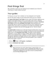
... the model purchased. Charging: The light shows amber when the battery is closed up. Note: The exact configuration of your PC depends on and off. 5 Keyboard For entering data into your computer. 6 Touchpad Touch-sensitive pointing device which functions like and right) the left and right mouse buttons. 9 Palmrest Comfortable support...
... the model purchased. Charging: The light shows amber when the battery is closed up. Note: The exact configuration of your PC depends on and off. 5 Keyboard For entering data into your computer. 6 Touchpad Touch-sensitive pointing device which functions like and right) the left and right mouse buttons. 9 Palmrest Comfortable support...
Service Guide
Page 3
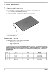
... the following stages: • External module disassembly • Main unit disassembly • LCD module disassembly The flowcharts provided in that you must first remove the keyboard, then disassemble the inside assembly frame in the succeeding disassembly sections illustrate the entire disassembly sequence. Unplug the AC adapter and all peripherals. 2.
... the following stages: • External module disassembly • Main unit disassembly • LCD module disassembly The flowcharts provided in that you must first remove the keyboard, then disassemble the inside assembly frame in the succeeding disassembly sections illustrate the entire disassembly sequence. Unplug the AC adapter and all peripherals. 2.
Service Guide
Page 4
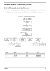
Item B C E Screw M2 x L3 M3 x L4 M2.5 x L6 Color Black Silver Black Part No. 86.00F80.723 86.9A524.4R0 86.00E12.536 Chapter 3 29 External Module Disassembly Process External Modules Disassembly Flowchart The flowchart below gives you a graphic representation on the entire disassembly sequence and instructs you must first remove the keyboard, then disassemble the inside assembly frame in that need to remove the main board, you on the components that order. For example, if you want to be removed during servicing.
Item B C E Screw M2 x L3 M3 x L4 M2.5 x L6 Color Black Silver Black Part No. 86.00F80.723 86.9A524.4R0 86.00E12.536 Chapter 3 29 External Module Disassembly Process External Modules Disassembly Flowchart The flowchart below gives you a graphic representation on the entire disassembly sequence and instructs you must first remove the keyboard, then disassemble the inside assembly frame in that need to remove the main board, you on the components that order. For example, if you want to be removed during servicing.
Service Guide
Page 18
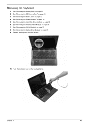
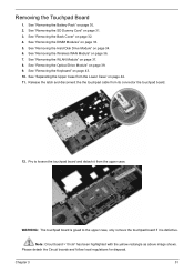
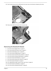
See "Removing the Battery Pack" on the touchpad area. Turn the keyboard over on page 30. 2. See "Removing the DIMM Modules" on page 32. 4. Release the keyboard from the latches. 10. See "Removing the Back Cover" on page 33. 5. See "Removing the Hard Disk Drive Module" on page 36. 7. See "Removing the Wireless WAN Module" on page 34. 6. Chapter 3 43 See "Removing the WLAN Module" on page 39. 9. Removing the Keyboard 1. See "Removing the Optical Drive Module" on page 37. 8. See "Removing the SD Dummy Card" on page 31. 3.
See "Removing the Battery Pack" on the touchpad area. Turn the keyboard over on page 30. 2. See "Removing the DIMM Modules" on page 32. 4. Release the keyboard from the latches. 10. See "Removing the Back Cover" on page 33. 5. See "Removing the Hard Disk Drive Module" on page 36. 7. See "Removing the Wireless WAN Module" on page 34. 6. Chapter 3 43 See "Removing the WLAN Module" on page 39. 9. Removing the Keyboard 1. See "Removing the Optical Drive Module" on page 37. 8. See "Removing the SD Dummy Card" on page 31. 3.
Service Guide
Page 19
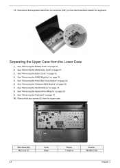
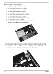
....5 x L6 (2) 44 Color Black Torque 1.6 kgf-cm Part No. 86.00E12.536 Chapter 3 See "Removing the Wireless WAN Module" on page 34. 6. See "Removing the Keyboard" on page 30. 2. See "Removing the Battery Pack" on page 43. 10. See "Removing the DIMM Modules" on the main board and detach the...
....5 x L6 (2) 44 Color Black Torque 1.6 kgf-cm Part No. 86.00E12.536 Chapter 3 See "Removing the Wireless WAN Module" on page 34. 6. See "Removing the Keyboard" on page 30. 2. See "Removing the Battery Pack" on page 43. 10. See "Removing the DIMM Modules" on the main board and detach the...
Service Guide
Page 23
See "Removing the Keyboard" on page 30. 2. See "Removing the Battery Pack" on page 43. 10. See "Removing the Back Cover" on page 37. 8. See "Removing the WLAN Module" ...
See "Removing the Keyboard" on page 30. 2. See "Removing the Battery Pack" on page 43. 10. See "Removing the Back Cover" on page 37. 8. See "Removing the WLAN Module" ...
Service Guide
Page 26
... 3 51 See "Removing the SD Dummy Card" on page 43. 10. Please detach the Circuit boards and follow local regulations for disposal. See "Removing the Keyboard" on page 31. 3. Note: Circuit board >10 cm² has been highlighted with the yellow rectangle as above image shows. See "Removing the Back Cover...
... 3 51 See "Removing the SD Dummy Card" on page 43. 10. Please detach the Circuit boards and follow local regulations for disposal. See "Removing the Keyboard" on page 31. 3. Note: Circuit board >10 cm² has been highlighted with the yellow rectangle as above image shows. See "Removing the Back Cover...
Service Guide
Page 27
... the power board. 52 Chapter 3 See "Removing the Optical Drive Module" on page 32. 4. See "Removing the Back Cover" on page 39. 9. See "Removing the Keyboard" on page 34. 6. See "Removing the Hard Disk Drive Module" on page 43. 10.
... the power board. 52 Chapter 3 See "Removing the Optical Drive Module" on page 32. 4. See "Removing the Back Cover" on page 39. 9. See "Removing the Keyboard" on page 34. 6. See "Removing the Hard Disk Drive Module" on page 43. 10.
Service Guide
Page 28
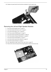
... Right Speaker Modules 1. See "Removing the SD Dummy Card" on page 32. 4. 13. See "Removing the Battery Pack" on page 43. 10. See "Removing the Keyboard" on page 30. 2. See "Removing the Hard Disk Drive Module" on page 33. 5. See "Removing the DIMM Modules" on page 34. 6. Remove the screws securing...
... Right Speaker Modules 1. See "Removing the SD Dummy Card" on page 32. 4. 13. See "Removing the Battery Pack" on page 43. 10. See "Removing the Keyboard" on page 30. 2. See "Removing the Hard Disk Drive Module" on page 33. 5. See "Removing the DIMM Modules" on page 34. 6. Remove the screws securing...
Service Guide
Page 29
.... 2. Release the speaker cables from the Lower Case" on page 32. 4. See "Removing the Hard Disk Drive Module" on page 43. 10. See "Removing the Keyboard" on page 34. 6. See "Removing the Optical Drive Module" on page 33. 5. See "Removing the DIMM Modules" on page 39. 9. See "Removing the LCD Module...
.... 2. Release the speaker cables from the Lower Case" on page 32. 4. See "Removing the Hard Disk Drive Module" on page 43. 10. See "Removing the Keyboard" on page 34. 6. See "Removing the Optical Drive Module" on page 33. 5. See "Removing the DIMM Modules" on page 39. 9. See "Removing the LCD Module...
Service Guide
Page 30
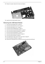
... the lower case. See "Removing the DIMM Modules" on page 44. 11. See "Removing the Optical Drive Module" on page 43. 10. See "Removing the Keyboard" on page 39. 9. See "Removing the USB Board Module" on page 31. 3. Chapter 3 55 See "Removing the SD Dummy Card" on page 54. See "Removing...
... the lower case. See "Removing the DIMM Modules" on page 44. 11. See "Removing the Optical Drive Module" on page 43. 10. See "Removing the Keyboard" on page 39. 9. See "Removing the USB Board Module" on page 31. 3. Chapter 3 55 See "Removing the SD Dummy Card" on page 54. See "Removing...
Service Guide
Page 32
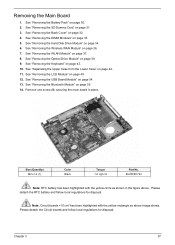
...-cm Part No. 86.00F80.723 Note: RTC battery has been highlighted with the yellow rectangle as shown in place. Chapter 3 57 See "Removing the Keyboard" on page 31. 3. Removing the Main Board 1. See "Removing the SD Dummy Card" on page 43. 10. See "Removing the WLAN Module" on page 36...
...-cm Part No. 86.00F80.723 Note: RTC battery has been highlighted with the yellow rectangle as shown in place. Chapter 3 57 See "Removing the Keyboard" on page 31. 3. Removing the Main Board 1. See "Removing the SD Dummy Card" on page 43. 10. See "Removing the WLAN Module" on page 36...
Service Guide
Page 33
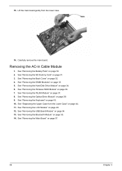
.... See "Removing the Bluetooth Module" on page 37. 8. Lift the main board gently from the Lower Case" on page 57. 58 Chapter 3 See "Removing the Keyboard" on page 48. 12. See "Removing the LCD Module" on page 43. 10. Carefully remove the main board. Removing the AC-in Cable Module 1. See...
.... See "Removing the Bluetooth Module" on page 37. 8. Lift the main board gently from the Lower Case" on page 57. 58 Chapter 3 See "Removing the Keyboard" on page 48. 12. See "Removing the LCD Module" on page 43. 10. Carefully remove the main board. Removing the AC-in Cable Module 1. See...
Service Guide
Page 34
... the DIMM Modules" on page 34. 6. See "Removing the Hard Disk Drive Module" on page 33. 5. 15. Disconnect AC-in cable module. See "Removing the Keyboard" on the main board. 16. Detach the AC-in cable from the Lower Case" on page 36. 7. See "Removing the Battery Pack" on page 54...
... the DIMM Modules" on page 34. 6. See "Removing the Hard Disk Drive Module" on page 33. 5. 15. Disconnect AC-in cable module. See "Removing the Keyboard" on the main board. 16. Detach the AC-in cable from the Lower Case" on page 36. 7. See "Removing the Battery Pack" on page 54...
Service Guide
Page 36
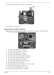
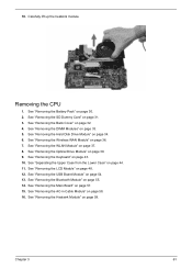
... 58. 16. See "Removing the AC-in Cable Module" on page 54. 13. See "Removing the WLAN Module" on page 43. 10. See "Removing the Keyboard" on page 37. 8. Carefully lift up the heatsink module. Removing the CPU 1. See "Removing the LCD Module" on page 59. See "Removing the Heatsink Module...
... 58. 16. See "Removing the AC-in Cable Module" on page 54. 13. See "Removing the WLAN Module" on page 43. 10. See "Removing the Keyboard" on page 37. 8. Carefully lift up the heatsink module. Removing the CPU 1. See "Removing the LCD Module" on page 59. See "Removing the Heatsink Module...
Service Guide
Page 40
... shown. Remove the two screws (A) from the bottom of the LCD module. 13. See "Removing the Optical Drive Module" on page 37. 8. See "Removing the Keyboard" on page 48. 12. See "Removing the LCD Module" on page 43. 10. Size (Quantity) M2.5 x L5 Chapter 3 Color Torque 3.0 kgf-cm Part No. 86...
... shown. Remove the two screws (A) from the bottom of the LCD module. 13. See "Removing the Optical Drive Module" on page 37. 8. See "Removing the Keyboard" on page 48. 12. See "Removing the LCD Module" on page 43. 10. Size (Quantity) M2.5 x L5 Chapter 3 Color Torque 3.0 kgf-cm Part No. 86...
Service Guide
Page 42
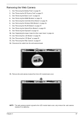
... Camera" on page 30. 2. Chapter 3 67 See "Removing the DIMM Modules" on page 37. 8. See "Removing the WLAN Module" on page 33. 5. See "Removing the Keyboard" on page 31. 3. Removing the Web Camera 1. NOTE: The web camera module is glued to the LCD module back cover, only remove the web camera...
... Camera" on page 30. 2. Chapter 3 67 See "Removing the DIMM Modules" on page 37. 8. See "Removing the WLAN Module" on page 33. 5. See "Removing the Keyboard" on page 31. 3. Removing the Web Camera 1. NOTE: The web camera module is glued to the LCD module back cover, only remove the web camera...

Service Guide
Page 43
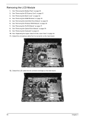
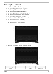
See "Removing the Battery Pack" on page 34. 6. See "Removing the Hard Disk Drive Module" on page 30. 2. See "Removing the Keyboard" on page 48. 12. See "Removing the LCD Module" on page 43. 10. Remove the six screws (D) securing the LCD panel with the Brackets 1. See "...
See "Removing the Battery Pack" on page 34. 6. See "Removing the Hard Disk Drive Module" on page 30. 2. See "Removing the Keyboard" on page 48. 12. See "Removing the LCD Module" on page 43. 10. Remove the six screws (D) securing the LCD panel with the Brackets 1. See "...

Service Guide
Page 44
See "Removing the Keyboard" on page 67. 14. See "Removing the Web Camera" on page 43. 10. Chapter 3 69 See "Removing the SD Dummy Card" on page 32. 4. See "...
See "Removing the Keyboard" on page 67. 14. See "Removing the Web Camera" on page 43. 10. Chapter 3 69 See "Removing the SD Dummy Card" on page 32. 4. See "...


