
Acer Aspire 1410 and Aspire 1680 Service Guide
Page 8
... 1 System Block Diagram 3 Board Layout 4 Top View 4 Bottom View 5 An Aspire Tour 7 Front View 7 Closed Front View 8 Left View 9 Right View 10 Rear Panel 11 Bottom Panel 12 Indicators 13 Using the Keyboard 15 Lock Keys 15 Embedded Numeric Keypad 16 Windows Keys 17 Hot Keys 18 Special...Utility 37 Information 38 Main 39 Advanced 41 Security 43 Boot 47 Exit 48 BIOS Flash Utility 49 Chapter 3 Machine Disassembly and Replacement 50 General Information 51 Before You Begin 51 Disassembly Procedure Flowchart 53 Removing the Battery Pack 55 Removing the HDD Module/the ...
... 1 System Block Diagram 3 Board Layout 4 Top View 4 Bottom View 5 An Aspire Tour 7 Front View 7 Closed Front View 8 Left View 9 Right View 10 Rear Panel 11 Bottom Panel 12 Indicators 13 Using the Keyboard 15 Lock Keys 15 Embedded Numeric Keypad 16 Windows Keys 17 Hot Keys 18 Special...Utility 37 Information 38 Main 39 Advanced 41 Security 43 Boot 47 Exit 48 BIOS Flash Utility 49 Chapter 3 Machine Disassembly and Replacement 50 General Information 51 Before You Begin 51 Disassembly Procedure Flowchart 53 Removing the Battery Pack 55 Removing the HDD Module/the ...
Acer Aspire 1410 and Aspire 1680 Service Guide
Page 9
...Optical Drive Module 66 Chapter 4 Troubleshooting 68 System Check Procedures 69 External Diskette Drive Check 69 External CD-ROM Drive Check 69 Keyboard or Auxiliary Input Device Check 69 Memory check 70 Power System Check 70 Touchpad Check 72 Power-On Self-Test (POST) ...Recovery 83 Disk to Disk Recovery 86 Chapter 5 Jumper and Connector Locations 90 Top View 90 Bottom View 92 Chapter 6 FRU (Field Replaceable Unit) List 94 Exploded Diagram 95 Appendix A Model Definition and Configuration 108 Model Name Definition 108 Appendix B Test Compatible Components 110 ...
...Optical Drive Module 66 Chapter 4 Troubleshooting 68 System Check Procedures 69 External Diskette Drive Check 69 External CD-ROM Drive Check 69 Keyboard or Auxiliary Input Device Check 69 Memory check 70 Power System Check 70 Touchpad Check 72 Power-On Self-Test (POST) ...Recovery 83 Disk to Disk Recovery 86 Chapter 5 Jumper and Connector Locations 90 Top View 90 Bottom View 92 Chapter 6 FRU (Field Replaceable Unit) List 94 Exploded Diagram 95 Appendix A Model Definition and Configuration 108 Model Name Definition 108 Appendix B Test Compatible Components 110 ...

Acer Aspire 1410 and Aspire 1680 Service Guide
Page 79
... the external diskette drive/DVD-ROM module. 2. External CD-ROM Drive Check Do the following to select the test device. 1. Replace the keyboard. 3. Replace the main board. If an error occurs with the internal diskette drive, reconnect the diskette connector on the System board. Do not... replace a non-defective FRU: 1. Follow the instructions in the message window. Do the following to isolate the problem to a controller, driver...
... the external diskette drive/DVD-ROM module. 2. External CD-ROM Drive Check Do the following to select the test device. 1. Replace the keyboard. 3. Replace the main board. If an error occurs with the internal diskette drive, reconnect the diskette connector on the System board. Do not... replace a non-defective FRU: 1. Follow the instructions in the message window. Do the following to isolate the problem to a controller, driver...
Acer Aspire 1410 and Aspire 1680 Service Guide
Page 84
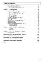
... 4 short beeps then shut down system, not show . Thermal critical High In this situation BIOS will show message. Keyboard Controller Failed see "Keyboard or Auxiliary Input Device Check" on page 69. Error Message List Error Messages FRU/Action in BIOS Setup Utility. ...battery Run BIOS Setup Utility to reconfigure system time, then reboot system. Keyboard locked - Incorrect password is dead - Keyboard error see "Keyboard or Auxiliary Input Device Check" on page 69. Replace and run Setup Replace RTC battery and Run BIOS Setup Utility to reconfigure system time, then...
... 4 short beeps then shut down system, not show . Thermal critical High In this situation BIOS will show message. Keyboard Controller Failed see "Keyboard or Auxiliary Input Device Check" on page 69. Error Message List Error Messages FRU/Action in BIOS Setup Utility. ...battery Run BIOS Setup Utility to reconfigure system time, then reboot system. Keyboard locked - Incorrect password is dead - Keyboard error see "Keyboard or Auxiliary Input Device Check" on page 69. Replace and run Setup Replace RTC battery and Run BIOS Setup Utility to reconfigure system time, then...

Acer Aspire 1410, 1810T, and 1810TZ Service Guide
Page 7
...Tour 5 Front View 5 Left View 7 Right View 7 Base View 8 Rear View 8 Indicators 9 TouchPad Basics 10 Using the Keyboard 11 Lock Keys and embedded numeric keypad 11 Windows Keys 12 Hot Keys 13 Special Keys 14 Hardware Specifications and Configurations 15 System ... HDD/BIOS Password Utilities 36 Removing BIOS Passwords 37 Miscellaneous Utilities 38 Machine Disassembly and Replacement 41 Disassembly Requirements 41 Related Information 41 Replacement Requirements 41 Pre-disassembly Instructions 42 Disassembly Process 43 External Module Disassembly Process 44 External ...
...Tour 5 Front View 5 Left View 7 Right View 7 Base View 8 Rear View 8 Indicators 9 TouchPad Basics 10 Using the Keyboard 11 Lock Keys and embedded numeric keypad 11 Windows Keys 12 Hot Keys 13 Special Keys 14 Hardware Specifications and Configurations 15 System ... HDD/BIOS Password Utilities 36 Removing BIOS Passwords 37 Miscellaneous Utilities 38 Machine Disassembly and Replacement 41 Disassembly Requirements 41 Related Information 41 Replacement Requirements 41 Pre-disassembly Instructions 42 Disassembly Process 43 External Module Disassembly Process 44 External ...
Acer Aspire 1410, 1810T, and 1810TZ Service Guide
Page 8
... Replacing the Speaker Modules 101 Replacing the RTC Battery 103 Replacing the Thermal Module 104 Replacing the CRT Board 105 Replacing the Main Board 106 Replacing the I/O Card 108 Replacing the Bluetooth Module 110 Replacing the LED Board 111 Replacing the LCD Module 113 Replacing the Button Board 115 Replacing the Upper Cover 118 Replacing the Keyboard 121 Replacing the Wireless LAN Module 122 Replacing...
... Replacing the Speaker Modules 101 Replacing the RTC Battery 103 Replacing the Thermal Module 104 Replacing the CRT Board 105 Replacing the Main Board 106 Replacing the I/O Card 108 Replacing the Bluetooth Module 110 Replacing the LED Board 111 Replacing the LCD Module 113 Replacing the Button Board 115 Replacing the Upper Cover 118 Replacing the Keyboard 121 Replacing the Wireless LAN Module 122 Replacing...

Acer Aspire 1410, 1810T, and 1810TZ Service Guide
Page 64
NOTE: The product previews seen in the same position. Main Unit Disassembly Flowchart Remove External Modules before proceeding Remove Keyboard Remove Upper Cover Remove Button Board Remove LCD Module Remove I/O Board Remove Bluetooth Module Remove LED Board Remove Mainboard Remove Speaker Module Remove CRT ... 54 Chapter 3 Main Unit Disassembly Process IMPORTANT: Cable paths and positioning may not represent the final product color or configuration. During the removal and replacement of components, ensure all available cable channels and clips are used and that the cables are...
NOTE: The product previews seen in the same position. Main Unit Disassembly Flowchart Remove External Modules before proceeding Remove Keyboard Remove Upper Cover Remove Button Board Remove LCD Module Remove I/O Board Remove Bluetooth Module Remove LED Board Remove Mainboard Remove Speaker Module Remove CRT ... 54 Chapter 3 Main Unit Disassembly Process IMPORTANT: Cable paths and positioning may not represent the final product color or configuration. During the removal and replacement of components, ensure all available cable channels and clips are used and that the cables are...

Acer Aspire 1410, 1810T, and 1810TZ Service Guide
Page 131
Replacing the Keyboard 1. Connect the FCC to the mainboard. 2. Push down the top edge ensuring the four latches across the top are fully secured. Turn the keyboard over and insert the bottom edge in. 3. Chapter 3 121
Replacing the Keyboard 1. Connect the FCC to the mainboard. 2. Push down the top edge ensuring the four latches across the top are fully secured. Turn the keyboard over and insert the bottom edge in. 3. Chapter 3 121

Acer Aspire 1410, 1810T, and 1810TZ Service Guide
Page 146
No Replace Keyboard Replace mainboard 136 Chapter 4 No Disconnect and reconnect Keyboard functioning? Built-In Keyboard Failure If the built-in Keyboard fails, perform the following actions one at a time to correct the problem. Do not replace non-defective FRUs: Start Keyboard properly connected?
No Replace Keyboard Replace mainboard 136 Chapter 4 No Disconnect and reconnect Keyboard functioning? Built-In Keyboard Failure If the built-in Keyboard fails, perform the following actions one at a time to correct the problem. Do not replace non-defective FRUs: Start Keyboard properly connected?

Acer Aspire 1410, 1810T, and 1810TZ Service Guide
Page 235
... display hotkeys 13 E Euro Key 14 External Module Disassembly Index Flowchart 44 F Features 1 FLASH Utility 33 Flash Utility 33 FRU (Field Replaceable Unit) List 151 H Hard Disk Drive Module Removing 47 Hibernation mode hotkey 13 Hot Keys 11 I Indicators 9 Intermittent Problems 142 Internal ...Microphone Failure 139 Internal Speaker Failure 138 J Jumper and Connector Locations 147 K Keyboard Removing 56 Keyboard Failure 136 L LCD Bezel Removing 79, 98 LCD Brackets Removing 86 LCD Cable Removing 86 LCD Failure 135 LCD Module Removing...
... display hotkeys 13 E Euro Key 14 External Module Disassembly Index Flowchart 44 F Features 1 FLASH Utility 33 Flash Utility 33 FRU (Field Replaceable Unit) List 151 H Hard Disk Drive Module Removing 47 Hibernation mode hotkey 13 Hot Keys 11 I Indicators 9 Intermittent Problems 142 Internal ...Microphone Failure 139 Internal Speaker Failure 138 J Jumper and Connector Locations 147 K Keyboard Removing 56 Keyboard Failure 136 L LCD Bezel Removing 79, 98 LCD Brackets Removing 86 LCD Cable Removing 86 LCD Failure 135 LCD Module Removing...


