Acer Aspire 1410 and Aspire 1680 Service Guide
Page 9
... Disassembling the LCD Module 64 Disassembling the External Modules 66 Disassembling the Optical Drive Module 66 Chapter 4 Troubleshooting 68 System Check Procedures 69 External Diskette Drive Check 69 External CD-ROM Drive Check 69 Keyboard or Auxiliary Input Device Check 69 Memory check 70 Power System...Error Message 78 Intermittent Problems 81 Undetermined Problems 82 Use NAPP CD to Build Master Hard Disc Drive 83 CD to Disk Recovery 83 Disk to Disk Recovery 86 Chapter 5 Jumper and Connector Locations 90 Top View 90 Bottom View 92 Chapter 6 FRU (Field Replaceable Unit)...
... Disassembling the LCD Module 64 Disassembling the External Modules 66 Disassembling the Optical Drive Module 66 Chapter 4 Troubleshooting 68 System Check Procedures 69 External Diskette Drive Check 69 External CD-ROM Drive Check 69 Keyboard or Auxiliary Input Device Check 69 Memory check 70 Power System...Error Message 78 Intermittent Problems 81 Undetermined Problems 82 Use NAPP CD to Build Master Hard Disc Drive 83 CD to Disk Recovery 83 Disk to Disk Recovery 86 Chapter 5 Jumper and Connector Locations 90 Top View 90 Bottom View 92 Chapter 6 FRU (Field Replaceable Unit)...

Acer Aspire 1410 and Aspire 1680 Service Guide
Page 37
...II Specification 3-in-1 card reader Item Chipset Protocol Specification TI PC7411 support Smart Media, Multi-Media Card and Security Digital Hard Disk Drive Interface Item Vendor & Model Name Capacity (MB) Bytes per sector Data heads HGST HTS424030M9AT00/ Toshiba Pluto MK3025GAS/ 30000... 27 Modem Interface Item Data modem data baud rate (bps) Supports modem protocol Modem connector type Modem connector location Bluetooth Interface Item Chipset Data throughput Protocol Interface Connector type 56K V.90/V.92 RJ11 Right panel Specification Specification Broadcom BCM2035 723 bps(full speed...
...II Specification 3-in-1 card reader Item Chipset Protocol Specification TI PC7411 support Smart Media, Multi-Media Card and Security Digital Hard Disk Drive Interface Item Vendor & Model Name Capacity (MB) Bytes per sector Data heads HGST HTS424030M9AT00/ Toshiba Pluto MK3025GAS/ 30000... 27 Modem Interface Item Data modem data baud rate (bps) Supports modem protocol Modem connector type Modem connector location Bluetooth Interface Item Chipset Data throughput Protocol Interface Connector type 56K V.90/V.92 RJ11 Right panel Specification Specification Broadcom BCM2035 723 bps(full speed...

Acer Aspire 1410 and Aspire 1680 Service Guide
Page 76
Detach the ODD holder. 5. Disconnect the ODD connector board then remove it. Push the ODD holder as the picture shows. 2. Remove another two screws holding the HDD bracket on the other side. 3. Chapter 3 66 Remove the two screws holding the HDD bracket on one side. 2. Disassembling the Optical Drive Module 1. Remove the two screws that secure the optical disc drive and the ODD holder. 3. Remove the four screws as shown. 4. Then take the hard disc drive out from the HDD bracket. Disassembling the External Modules Disassembling the HDD Module 1.
Detach the ODD holder. 5. Disconnect the ODD connector board then remove it. Push the ODD holder as the picture shows. 2. Remove another two screws holding the HDD bracket on the other side. 3. Chapter 3 66 Remove the two screws holding the HDD bracket on one side. 2. Disassembling the Optical Drive Module 1. Remove the two screws that secure the optical disc drive and the ODD holder. 3. Remove the four screws as shown. 4. Then take the hard disc drive out from the HDD bracket. Disassembling the External Modules Disassembling the HDD Module 1.
Acer Aspire 1410 and Aspire 1680 Service Guide
Page 84
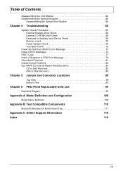
Error Message List Error Messages FRU/Action in BIOS Setup Utility. "Load Default Settings" in Sequence Failure Fixed Disk Reconnect hard disk drive connector. Keyboard Controller Failed see "Keyboard or Auxiliary Input Device Check" on page 69. Run Setup Run "Load Default Settings" ...2. Incorrect password is dead - System timer error RTC battery Run BIOS Setup Utility to reconfigure system time, then reboot system. Hard disk drive System board Stuck Key see "Keyboard or Auxiliary Input Device Check" on page 69. Keyboard locked - IDE Primary Channel Master...
Error Message List Error Messages FRU/Action in BIOS Setup Utility. "Load Default Settings" in Sequence Failure Fixed Disk Reconnect hard disk drive connector. Keyboard Controller Failed see "Keyboard or Auxiliary Input Device Check" on page 69. Run Setup Run "Load Default Settings" ...2. Incorrect password is dead - System timer error RTC battery Run BIOS Setup Utility to reconfigure system time, then reboot system. Hard disk drive System board Stuck Key see "Keyboard or Auxiliary Input Device Check" on page 69. Keyboard locked - IDE Primary Channel Master...
Acer Aspire 1410 and Aspire 1680 Service Guide
Page 86
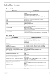
...adapter). Reconnect the DIMM. No beep, power-on indicator turns on LCD during POST but system runs correctly. Reconnect the LCD connectors. Ensure every connector is connected tightly and correctly. Speaker System board Chapter 4 76 LED board. System board. Power source (battery pack and power ...you can see POST on and LCD is blank. System board No beep during POST. Ensure every connector is connected tightly and correctly. Reconnect the LCD connector Hard disk drive LCD inverter ID LCD cable LCD Inverter LCD System board No beep, power-on indicator turns on an...
...adapter). Reconnect the DIMM. No beep, power-on indicator turns on LCD during POST but system runs correctly. Reconnect the LCD connectors. Ensure every connector is connected tightly and correctly. Speaker System board Chapter 4 76 LED board. System board. Power source (battery pack and power ...you can see POST on and LCD is blank. System board No beep during POST. Ensure every connector is connected tightly and correctly. Reconnect the LCD connector Hard disk drive LCD inverter ID LCD cable LCD Inverter LCD System board No beep, power-on indicator turns on an...

Acer Aspire 1410 and Aspire 1680 Service Guide
Page 88
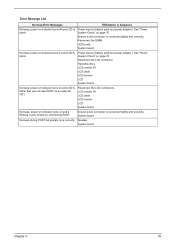
... / Error LCD backlight doesn't work ). Battery pack Power adapter Hard drive & battery connection board System board Power source (battery pack and power adapter). See "Power System Check" on page 70. LCD inverter ID LCD cable LCD inverter LCD System board Reconnect the LCD connector LCD inverter ID LCD cable LCD inverter LCD System...
... / Error LCD backlight doesn't work ). Battery pack Power adapter Hard drive & battery connection board System board Power source (battery pack and power adapter). See "Power System Check" on page 70. LCD inverter ID LCD cable LCD inverter LCD System board Reconnect the LCD connector LCD inverter ID LCD cable LCD inverter LCD System...

Acer Aspire 1410, 1810T, and 1810TZ Service Guide
Page 235
...14 External Module Disassembly Index Flowchart 44 F Features 1 FLASH Utility 33 Flash Utility 33 FRU (Field Replaceable Unit) List 151 H Hard Disk Drive Module Removing 47 Hibernation mode hotkey 13 Hot Keys 11 I Indicators 9 Intermittent Problems 142 Internal Microphone Failure 139 Internal Speaker Failure 138... J Jumper and Connector Locations 147 K Keyboard Removing 56 Keyboard Failure 136 L LCD Bezel Removing 79, 98 LCD ...
...14 External Module Disassembly Index Flowchart 44 F Features 1 FLASH Utility 33 Flash Utility 33 FRU (Field Replaceable Unit) List 151 H Hard Disk Drive Module Removing 47 Hibernation mode hotkey 13 Hot Keys 11 I Indicators 9 Intermittent Problems 142 Internal Microphone Failure 139 Internal Speaker Failure 138... J Jumper and Connector Locations 147 K Keyboard Removing 56 Keyboard Failure 136 L LCD Bezel Removing 79, 98 LCD ...


