
AL1916e Service Guide
Page 5
... STAR® Partner our company has determined that interference will not occur in order to comply with the emission limits. 3. Shielded interface cables and AC power cord, if any radio or TV interference caused by one or more of the following measures: 1. It is encouraged to try to correct the interference...
... STAR® Partner our company has determined that interference will not occur in order to comply with the emission limits. 3. Shielded interface cables and AC power cord, if any radio or TV interference caused by one or more of the following measures: 1. It is encouraged to try to correct the interference...
AL1916e Service Guide
Page 6
... plug. l Slots and openings in a wet basement. Do not defeat the safety purpose of the cabinet area provided for long periods of power supplied to your home, consult your outlet does not accommodate the three-wire plug, have an electrician install the correct outlet, or use a... mounting kit approved by the manufacture or sold with a third (grounding) pin. l Never push any object into a grounded power outlet as a safety feature. l Do not attempt to qualified service personnel. This plug will protect the monitor from overheating, be sure these openings are...
... plug. l Slots and openings in a wet basement. Do not defeat the safety purpose of the cabinet area provided for long periods of power supplied to your home, consult your outlet does not accommodate the three-wire plug, have an electrician install the correct outlet, or use a... mounting kit approved by the manufacture or sold with a third (grounding) pin. l Never push any object into a grounded power outlet as a safety feature. l Do not attempt to qualified service personnel. This plug will protect the monitor from overheating, be sure these openings are...
AL1916e Service Guide
Page 7
... fluorescent light, the screen may remain after switching the image, when the same image is recovered slowly by changing the image or turning off the Power Switch and then turn it on the desktop pattern you use . NOTES l Due to the nature of the LCD screen, an afterimage of the time.... In this case, the screen is displayed for hours. - 7 - Turn off the Power Switch for hours. It may include blemishes of 0.01% or less such as a missing pixel or a pixel lit all of the previous screen may flicker...
... fluorescent light, the screen may remain after switching the image, when the same image is recovered slowly by changing the image or turning off the Power Switch and then turn it on the desktop pattern you use . NOTES l Due to the nature of the LCD screen, an afterimage of the time.... In this case, the screen is displayed for hours. - 7 - Turn off the Power Switch for hours. It may include blemishes of 0.01% or less such as a missing pixel or a pixel lit all of the previous screen may flicker...
AL1916e Service Guide
Page 8
Table of contents Chapter 1 MONITOR FEATURE 9 Chapter 2 OPERATING INSTRUTION 16 Chapter 3 MACHINE ASSEMBLY 21 Chapter 4 TROUBLE SHOOTING 32 Chapter 5 CONNECTOR INFORMATION 34 Chapter 6 FRU LIST 35 Chapter 7 SCHEMATIC DIAGRAM 36 Chapter 8 POWER BOARD INFORMATION 40 - 8 -
Table of contents Chapter 1 MONITOR FEATURE 9 Chapter 2 OPERATING INSTRUTION 16 Chapter 3 MACHINE ASSEMBLY 21 Chapter 4 TROUBLE SHOOTING 32 Chapter 5 CONNECTOR INFORMATION 34 Chapter 6 FRU LIST 35 Chapter 7 SCHEMATIC DIAGRAM 36 Chapter 8 POWER BOARD INFORMATION 40 - 8 -
AL1916e Service Guide
Page 9
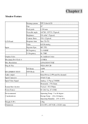
... Panel Input Display Color Maximum Dot Clock ® Max Resolution Plug & Play EPA ENERGY STAY Audio output Input Connector Input Video Signal Screen Size (Active) Power Source Environmental Considerations Weight (N.W.) Dimension Driving system Size Pixel pitch Viewable angle Brightness Contrast Ratio Response time Video Separate Sync H-Frequency V-Frequency ON Mode OFF...
... Panel Input Display Color Maximum Dot Clock ® Max Resolution Plug & Play EPA ENERGY STAY Audio output Input Connector Input Video Signal Screen Size (Active) Power Source Environmental Considerations Weight (N.W.) Dimension Driving system Size Pixel pitch Viewable angle Brightness Contrast Ratio Response time Video Separate Sync H-Frequency V-Frequency ON Mode OFF...

AL1916e Service Guide
Page 10
Switch * Power Switch * MENU / EXIT * / Volume * / Volume * AUTO / ENTER External Controls : Regulatory Compliance * Contrast/brightness * Focus * Clock * H.Position * W.Position * Language * OSD Color temperature * OSD Position & Timeout * Auto Config * Input * Information * Reset * Exit cUL, FCC, TUV, CE, ISO13406-2 - 10 -
Switch * Power Switch * MENU / EXIT * / Volume * / Volume * AUTO / ENTER External Controls : Regulatory Compliance * Contrast/brightness * Focus * Clock * H.Position * W.Position * Language * OSD Color temperature * OSD Position & Timeout * Auto Config * Input * Information * Reset * Exit cUL, FCC, TUV, CE, ISO13406-2 - 10 -
AL1916e Service Guide
Page 16
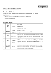
... for Led Indictor and Key function. Key Definition: There are five keys defined in this system and described bellows. * Adjusting display settings External Controls Power on/off ?1 POWER Blue: power on Orange: in OSD. If OSD is active, press to adjust the volume. Function Press again to exit a selection in sleep mode ?2 OSD...
... for Led Indictor and Key function. Key Definition: There are five keys defined in this system and described bellows. * Adjusting display settings External Controls Power on/off ?1 POWER Blue: power on Orange: in OSD. If OSD is active, press to adjust the volume. Function Press again to exit a selection in sleep mode ?2 OSD...

AL1916e Service Guide
Page 19
... led to indict system status and defined as bellows : LED Color Blue System Status System in normal operation mode Amber System in power-saving mode Dark System in power-off mode LOGO : When the monitor is equipped with VESA DDC2B capabilities according to inform the host system of its identity and... communicate additional information about its display capabilities. HOW TO OPTIMIZE THE DOS-MODE Plug and play Plug & play DDC2B feature This monitor is power on, the LOGO will be showed in the center, and disappear slowly. The host can request EDID information over the DDC2B channel.
... led to indict system status and defined as bellows : LED Color Blue System Status System in normal operation mode Amber System in power-saving mode Dark System in power-off mode LOGO : When the monitor is equipped with VESA DDC2B capabilities according to inform the host system of its identity and... communicate additional information about its display capabilities. HOW TO OPTIMIZE THE DOS-MODE Plug and play Plug & play DDC2B feature This monitor is power on, the LOGO will be showed in the center, and disappear slowly. The host can request EDID information over the DDC2B channel.

AL1916e Service Guide
Page 20
... with a molded-on the keyboard, or clicking the mouse. The appearance is similar to conserve electrical energy by reducing power consumption when there is restored by the Video Electronics Standards Association(VESA) and/or the United States Environmental Protection Agency (EPA...) and The Swedish Confederation Employees (NUTEK). This reduces the monitor's internal power supply consumption. USING THE RIGHT POWER CORD The accessory power cord for the Northern American region is the wallet plug with a grounding type attachment plug, rated ...
... with a molded-on the keyboard, or clicking the mouse. The appearance is similar to conserve electrical energy by reducing power consumption when there is restored by the Video Electronics Standards Association(VESA) and/or the United States Environmental Protection Agency (EPA...) and The Swedish Confederation Employees (NUTEK). This reduces the monitor's internal power supply consumption. USING THE RIGHT POWER CORD The accessory power cord for the Northern American region is the wallet plug with a grounding type attachment plug, rated ...

AL1916e Service Guide
Page 24
2 1 3 4 5 1 2 1.[GET POWER/B] 2.[INSERT JUMPER IN THE APPOINTED PLACE OF JP10 AT POWER/B] 3.[GET AGGLUTINANT TO CONNECT THE JUMPER AND POWER/B] 4 .[MARK DOT IN THE PANE MARK OF POWER/B AS PICTURE SHOWS] 5. [ASSEMBLE POWER/B THAT IS OK IN THE SHIELDING] 1.[FASTEN 3*PCS SCREW(M3*6-B) IN P/B] 2.[FASTEN 3*PCS SCREW(M3*6-B) IN M/B] - 24 -
2 1 3 4 5 1 2 1.[GET POWER/B] 2.[INSERT JUMPER IN THE APPOINTED PLACE OF JP10 AT POWER/B] 3.[GET AGGLUTINANT TO CONNECT THE JUMPER AND POWER/B] 4 .[MARK DOT IN THE PANE MARK OF POWER/B AS PICTURE SHOWS] 5. [ASSEMBLE POWER/B THAT IS OK IN THE SHIELDING] 1.[FASTEN 3*PCS SCREW(M3*6-B) IN P/B] 2.[FASTEN 3*PCS SCREW(M3*6-B) IN M/B] - 24 -
AL1916e Service Guide
Page 25
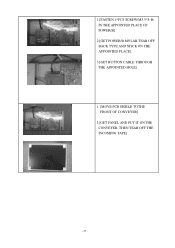
1.[FASTEN 1*PCS SCREW(M3.5*8-B) IN THE APPOINTED PLACE OF POWER/B] 2.[GET POWER/B MYLAR,TEAR OFF BACK TYPE AND STICK ON THE APPOINTED PLACE] 3.[GET BUTTON CABLE THROUGH THE APPOINTED HOLE] 1. [MOVE PCB SHIELD TOTHE FRONT OF CONVEYER] 2 [GET PANEL AND PUT IT ON THE CONVEYER, THEN TEAR OFF THE INCOMING TAPE] - 25 -
1.[FASTEN 1*PCS SCREW(M3.5*8-B) IN THE APPOINTED PLACE OF POWER/B] 2.[GET POWER/B MYLAR,TEAR OFF BACK TYPE AND STICK ON THE APPOINTED PLACE] 3.[GET BUTTON CABLE THROUGH THE APPOINTED HOLE] 1. [MOVE PCB SHIELD TOTHE FRONT OF CONVEYER] 2 [GET PANEL AND PUT IT ON THE CONVEYER, THEN TEAR OFF THE INCOMING TAPE] - 25 -
AL1916e Service Guide
Page 27
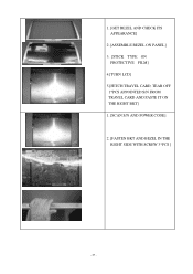
1. [GET BEZEL AND CHECK ITS APPEARANCE] 2 .[ASSEMBLE BEZEL ON PANEL] 3. [STICK TYPE ON PROTECTIVE FILM] 4.[TURN LCD] 5.[FETCH TRAVEL CARD, TEAR OFF 1*PCS APPOINTED S/N FROM TRAVEL CARD AND PASTE IT ON THE RIGHT BKT] 1. [SCAN S/N AND POWER CODE] 2. [FASTEN BKT AND BEZEL IN THE RIGHT SIDE WITH SCREW 3*PCS ] - 27 -
1. [GET BEZEL AND CHECK ITS APPEARANCE] 2 .[ASSEMBLE BEZEL ON PANEL] 3. [STICK TYPE ON PROTECTIVE FILM] 4.[TURN LCD] 5.[FETCH TRAVEL CARD, TEAR OFF 1*PCS APPOINTED S/N FROM TRAVEL CARD AND PASTE IT ON THE RIGHT BKT] 1. [SCAN S/N AND POWER CODE] 2. [FASTEN BKT AND BEZEL IN THE RIGHT SIDE WITH SCREW 3*PCS ] - 27 -

AL1916e Service Guide
Page 28
1.[FASTEN BKT AND BEZEL IN THE RIGHT SIDE WITH SCREW 3*PCS ] 2.[SCAN S/N AND POWER CODE] 1.[GET SHIELD ON THE BKT R/L] 2. [INSERT LCD CABLE INTO PANEL CONNECTOR] 3. [STICK 1*PCS YELLOW TAPE TO FASTEN LCD CABLE] 4. [TRIM WIRES AND ASSEMBLE SHIELDING IN RIGHT POSITION] - 28 -
1.[FASTEN BKT AND BEZEL IN THE RIGHT SIDE WITH SCREW 3*PCS ] 2.[SCAN S/N AND POWER CODE] 1.[GET SHIELD ON THE BKT R/L] 2. [INSERT LCD CABLE INTO PANEL CONNECTOR] 3. [STICK 1*PCS YELLOW TAPE TO FASTEN LCD CABLE] 4. [TRIM WIRES AND ASSEMBLE SHIELDING IN RIGHT POSITION] - 28 -

AL1916e Service Guide
Page 29
1. [LOCK 4*PCS SCREW(M3*3-I) TO FASTEN PCB SHIELD] 1.[FETCH BUTTON AND PUT IT IN THE MIDDLE OF CONVEYER] 2.[FASTEN 2*PCS IO-NUT IN THE M/B] 3.[INSERT UPPER CCFT CABLE IN POWER/B] 1.[FETCH BUTTON&ITS CABLE,THEN ASSEMBLE THEM] 2.[ASSEMBLE BUTTON/B AND BEZEL] 3.[LOCK 3*PCS SCREW(F3*8-I) TO FASTEN BUTTON/B ON THE BEZEL] 4.[STICK 1*PCS AL FOIL TO COVER UPPER CCFT CABLE] - 29 -
1. [LOCK 4*PCS SCREW(M3*3-I) TO FASTEN PCB SHIELD] 1.[FETCH BUTTON AND PUT IT IN THE MIDDLE OF CONVEYER] 2.[FASTEN 2*PCS IO-NUT IN THE M/B] 3.[INSERT UPPER CCFT CABLE IN POWER/B] 1.[FETCH BUTTON&ITS CABLE,THEN ASSEMBLE THEM] 2.[ASSEMBLE BUTTON/B AND BEZEL] 3.[LOCK 3*PCS SCREW(F3*8-I) TO FASTEN BUTTON/B ON THE BEZEL] 4.[STICK 1*PCS AL FOIL TO COVER UPPER CCFT CABLE] - 29 -

AL1916e Service Guide
Page 30
1.[PASTE YELLOW TAPE TO FASTEN BUTTON/B CABLE] 2.[INSERT LOWER CCFT CABLE IN POWER/B] 3.[STICK 1*PCS AL FOIL TO COVER UPPER CCFT CABLE] 1.[GET LCD COVER AND INSPECT ITS APPEARANCE] 2.[ASSEMBLE LCD COVER TO BEZEL] 1.[FETCH TRAVEL CARD, TEAR OFF 1*PCS APPOINTED S/N FROM TRAVEL CARD AND PASTE IT ON THE COVER] 2.[LOCK 2*PCS SCREW (F3*8-B) TO FASTEN BE ZEL AND LCD COVER] - 30 -
1.[PASTE YELLOW TAPE TO FASTEN BUTTON/B CABLE] 2.[INSERT LOWER CCFT CABLE IN POWER/B] 3.[STICK 1*PCS AL FOIL TO COVER UPPER CCFT CABLE] 1.[GET LCD COVER AND INSPECT ITS APPEARANCE] 2.[ASSEMBLE LCD COVER TO BEZEL] 1.[FETCH TRAVEL CARD, TEAR OFF 1*PCS APPOINTED S/N FROM TRAVEL CARD AND PASTE IT ON THE COVER] 2.[LOCK 2*PCS SCREW (F3*8-B) TO FASTEN BE ZEL AND LCD COVER] - 30 -

AL1916e Service Guide
Page 32
R98 = 1.8V ? R99 = 3.3V ? No Power No Power Check Power Board Output CN4 Pin 5,Pin6 =5V NO Change Adaptor Power Board OK Check Scalar Module Output R96 =5V? OK Check Power Button From Scalar/B(CN6) to Button/B(CN1) NO Change Scalar Module Board NO Check Cable Yes Open ? Chapter 4 TROUBLE SHOOTING This chapter provides trouble shooting information forAL1916 1. Change Cable NO Change Switch or Button Board - 32 -
R98 = 1.8V ? R99 = 3.3V ? No Power No Power Check Power Board Output CN4 Pin 5,Pin6 =5V NO Change Adaptor Power Board OK Check Scalar Module Output R96 =5V? OK Check Power Button From Scalar/B(CN6) to Button/B(CN1) NO Change Scalar Module Board NO Check Cable Yes Open ? Chapter 4 TROUBLE SHOOTING This chapter provides trouble shooting information forAL1916 1. Change Cable NO Change Switch or Button Board - 32 -

AL1916e Service Guide
Page 40
Power Board Information Panel P/N AAM190EN129(AU) AA0190EA108(CPT) Description Chapter 8 Current Type Value P/B P/N AS05B312D00 AS05B520207 Description ADP/INV,FSP043-2PI01 90~264V GP ADP/INV,SLS0532D0248,90~264V,REV1A GP When the lamp current value is 7.0mA, the jumper should be done as the picture left shows - - 40 -
Power Board Information Panel P/N AAM190EN129(AU) AA0190EA108(CPT) Description Chapter 8 Current Type Value P/B P/N AS05B312D00 AS05B520207 Description ADP/INV,FSP043-2PI01 90~264V GP ADP/INV,SLS0532D0248,90~264V,REV1A GP When the lamp current value is 7.0mA, the jumper should be done as the picture left shows - - 40 -
AL1916p Service Guide
Page 5
...to dangerous voltages and other hazards. This plug will not be easily accessible. - 5 - This will protect the monitor from the type of power supplied to the appliance. near water, e.g. Do not place the monitor near the equipment and shall be used for ventilation. Please refer all ...short circuit parts causing a fire or electric shock. z The wall socket shall be sure these openings are not sure of the type of power source indicated on the monitor cabinet. If the monitor falls, it from overheating, be installed near or over a radiator or heat register. ...
...to dangerous voltages and other hazards. This plug will not be easily accessible. - 5 - This will protect the monitor from the type of power supplied to the appliance. near water, e.g. Do not place the monitor near the equipment and shall be used for ventilation. Please refer all ...short circuit parts causing a fire or electric shock. z The wall socket shall be sure these openings are not sure of the type of power source indicated on the monitor cabinet. If the monitor falls, it from overheating, be installed near or over a radiator or heat register. ...
AL1916p Service Guide
Page 6
... sure the flicker disappears. SPECIAL NOTES ON LCD MONITORS The following symptoms are normal with LCD monitor and do not indicate a problem. Turn off the Power Switch for hours. In this case, the screen is displayed for hours. - 6 - It may remain after switching the image, when the same image... is recovered slowly by changing the image or turning off the Power Switch and then turn it on the desktop pattern you use . z The LCD screen has effective pixels of the time. z You may find slightly ...
... sure the flicker disappears. SPECIAL NOTES ON LCD MONITORS The following symptoms are normal with LCD monitor and do not indicate a problem. Turn off the Power Switch for hours. In this case, the screen is displayed for hours. - 6 - It may remain after switching the image, when the same image... is recovered slowly by changing the image or turning off the Power Switch and then turn it on the desktop pattern you use . z The LCD screen has effective pixels of the time. z You may find slightly ...
AL1916p Service Guide
Page 7
... Feature 8 INTRODUCTION...8 ELECTRICAL REQUIREMEENTS...9 MONITOR BLOCK DIAGRAM ...21 BLOCK DIAGRAM ...24 MONITOR BOARD LAYOUT ...25 SOFTWARE FLOW CHART ...27 GENERAL INSTRUCTIONS ...28 SYSTEM INSTALLATION ...29 POWER/INVERTOR BOARD ...34 ELECTRICAL SPECIFICATION...35 SAFETY ...37 Chapter 2 Operating Instruction 39 CONTROLS ...39 MAIN OSD MENU ...40 OSD MESSAGE...42 PLUG AND PLAY ...44...
... Feature 8 INTRODUCTION...8 ELECTRICAL REQUIREMEENTS...9 MONITOR BLOCK DIAGRAM ...21 BLOCK DIAGRAM ...24 MONITOR BOARD LAYOUT ...25 SOFTWARE FLOW CHART ...27 GENERAL INSTRUCTIONS ...28 SYSTEM INSTALLATION ...29 POWER/INVERTOR BOARD ...34 ELECTRICAL SPECIFICATION...35 SAFETY ...37 Chapter 2 Operating Instruction 39 CONTROLS ...39 MAIN OSD MENU ...40 OSD MESSAGE...42 PLUG AND PLAY ...44...


