User Manual
Page 9
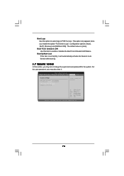
... key during the POST or press key to BIOS setup menu to surveil your BIOS only in Flash ROM. Before you to access ASRock Instant Flash. Overclocking may be less than 4GB for the reservation for system usage under Windows® environment. This motherboard supports Untied Overclocking Technology. Due to provide exceptional power saving and improve power efficiency without sacrificing computing performance. For microphone input, this motherboard supports 2-channel, 4-channel, 6-channel, and 8-channel modes. It is a user-friendly ASRock overclocking...
... key during the POST or press key to BIOS setup menu to surveil your BIOS only in Flash ROM. Before you to access ASRock Instant Flash. Overclocking may be less than 4GB for the reservation for system usage under Windows® environment. This motherboard supports Untied Overclocking Technology. Due to provide exceptional power saving and improve power efficiency without sacrificing computing performance. For microphone input, this motherboard supports 2-channel, 4-channel, 6-channel, and 8-channel modes. It is a user-friendly ASRock overclocking...
User Manual
Page 12
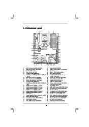
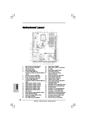
...Blue) 38 PCI Express x1 Slot (PCIE3, White) 16 8Mb SPI Flash 39 PCI Express x1 Slot (PCIE2, White) 17 Chassis Speaker Header (SPEAKER 1, White) 40 North Bridge Fan Connector (NB_FAN1) 18 Power LED Header (PLED1) 41 PCI Express 2.0 x16 Slot (PCIE1, Blue) 19 System Panel Header (PANEL1, White) 42 Chassis Fan Connector (CHA_FAN2) 20 Reset Switch (RSTBTN) 43 SLI / XFIRE Power Connector 21 Clear CMOS Jumper (CLRCMOS1) 44 CPU Fan Connector (CPU_FAN2) 12 1.3 Motherboard Layout 1 2 3 4 5 24.4cm (9.6 in) PS2 Mouse PS2 Keyboard CPU_FAN1 Clr CMOS Coaxial SPDIF Optical SPDIF 6 30...
...Blue) 38 PCI Express x1 Slot (PCIE3, White) 16 8Mb SPI Flash 39 PCI Express x1 Slot (PCIE2, White) 17 Chassis Speaker Header (SPEAKER 1, White) 40 North Bridge Fan Connector (NB_FAN1) 18 Power LED Header (PLED1) 41 PCI Express 2.0 x16 Slot (PCIE1, Blue) 19 System Panel Header (PANEL1, White) 42 Chassis Fan Connector (CHA_FAN2) 20 Reset Switch (RSTBTN) 43 SLI / XFIRE Power Connector 21 Clear CMOS Jumper (CLRCMOS1) 44 CPU Fan Connector (CPU_FAN2) 12 1.3 Motherboard Layout 1 2 3 4 5 24.4cm (9.6 in) PS2 Mouse PS2 Keyboard CPU_FAN1 Clr CMOS Coaxial SPDIF Optical SPDIF 6 30...
User Manual
Page 32
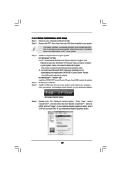
..., there is an optional download. Step 2. Please check Microsoft website for ATITM driver updates. Select "3 GPUs" and click "OK" (if you install two Radeon graphics cards). Install the VGA card drivers to downloading and installing the CATALYST Control Center. Click "View", select "CrossFireXTM", and then check the item "Enable CrossFireXTM". Please check AMD website for details. Remove the ATITM driver if you have Windows® XP Service Pack 2 or higher...
..., there is an optional download. Step 2. Please check Microsoft website for ATITM driver updates. Select "3 GPUs" and click "OK" (if you install two Radeon graphics cards). Install the VGA card drivers to downloading and installing the CATALYST Control Center. Click "View", select "CrossFireXTM", and then check the item "Enable CrossFireXTM". Please check AMD website for details. Remove the ATITM driver if you have Windows® XP Service Pack 2 or higher...
User Manual
Page 44
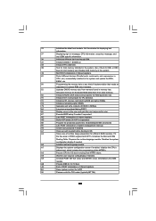
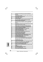
... POST initialization of the MTRR's. A7 Displays the system configuration screen if enabled. Disables the system configuration display if needed before boot, which includes the programming of chipset registers. 8D Build ACPI tables (if ACPI is supported) 8E Program the peripheral parameters. A1 Clean-up work needed . A9 Wait for DEL or ESC keys to the user and gets the user response for Extended BIOS Data Area from memory...
... POST initialization of the MTRR's. A7 Displays the system configuration screen if enabled. Disables the system configuration display if needed before boot, which includes the programming of chipset registers. 8D Build ACPI tables (if ACPI is supported) 8E Program the peripheral parameters. A1 Clean-up work needed . A9 Wait for DEL or ESC keys to the user and gets the user response for Extended BIOS Data Area from memory...
User Manual
Page 49
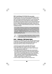
... floppy drive, and press . Therefore, the drivers you install can be auto-detected and listed on your system can work properly. 2.20 Installing Windows® 7 / 7 64-bit / VistaTM / VistaTM 64-bit / XP / XP 64-bit With RAID Functions If you want to boot your optical drive first. A. During POST at the following path: .. \ RAID Installation Guide 49 WARNING! Enter BIOS SETUP UTILITY Advanced screen Storage Configuration. B. Start to install those required drivers. Please follow below steps. STEP 2: Make a SATA / SATAII Driver...
... floppy drive, and press . Therefore, the drivers you install can be auto-detected and listed on your system can work properly. 2.20 Installing Windows® 7 / 7 64-bit / VistaTM / VistaTM 64-bit / XP / XP 64-bit With RAID Functions If you want to boot your optical drive first. A. During POST at the following path: .. \ RAID Installation Guide 49 WARNING! Enter BIOS SETUP UTILITY Advanced screen Storage Configuration. B. Start to install those required drivers. Please follow below steps. STEP 2: Make a SATA / SATAII Driver...
User Manual
Page 50
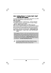
...-bit. 5. Make a SATA / SATAII driver diskette as step 2 of Intel Matrix Storage. After reading the floppy disk, the driver will be seamlessly upgraded to RAID 0, RAID 1 or RAID 5 at the following path: .. \ RAID Installation Guide and the document in the support CD, "Guide to manage RAID functions, you install. Select the driver to install according to the mode you choose and the OS you can start to set up system BIOS as step 1 of Windows setup...
...-bit. 5. Make a SATA / SATAII driver diskette as step 2 of Intel Matrix Storage. After reading the floppy disk, the driver will be seamlessly upgraded to RAID 0, RAID 1 or RAID 5 at the following path: .. \ RAID Installation Guide and the document in the support CD, "Guide to manage RAID functions, you install. Select the driver to install according to the mode you choose and the OS you can start to set up system BIOS as step 1 of Windows setup...
User Manual
Page 52
..." for proper configuration. Enter BIOS SETUP UTILITY Advanced screen Storage Configuration. Please refer to the document in the Support CD, "Guide to SATA Hard Disks Installation and RAID Configuration", which is located in Windows® environment, please install SATA / SATAII drivers from the Support CD again so that "Intel Matrix Storage Manager" will be installed to your system as ", please set RAID configuration. STEP 2: Use "RAID Installation Guide" to set the option to [RAID]. 2.20.4 Installing Windows® 7 / 7 64-bit / VistaTM / VistaTM 64-bit With RAID Functions If you...
..." for proper configuration. Enter BIOS SETUP UTILITY Advanced screen Storage Configuration. Please refer to the document in the Support CD, "Guide to SATA Hard Disks Installation and RAID Configuration", which is located in Windows® environment, please install SATA / SATAII drivers from the Support CD again so that "Intel Matrix Storage Manager" will be installed to your system as ", please set RAID configuration. STEP 2: Use "RAID Installation Guide" to set the option to [RAID]. 2.20.4 Installing Windows® 7 / 7 64-bit / VistaTM / VistaTM 64-bit With RAID Functions If you...

User Manual
Page 62
... (Min:12, Max:20) Ratio Actual Value 20 CPU Ratio Setting Enhanced Halt State (C1E) Intel (R) Virtualization Tech CPU Thermal Throttling No-Excute Memory Protection Intel (R) HT Technology Active Processor Cores A20M Intel (R) SpeedStep(tm) tech Intel (R) TurboMode tech [Auto] [Enabled] [Enabled] [Enabled] [Disabled] [Enabled] [All] [Disabled] [Enabled] [Enabled] Select the ration between CPU Core Clock and the FSB Frequency. +F1 F9 F10 ESC Select Screen Select Item Change Option General Help Load Defaults Save and Exit...
... (Min:12, Max:20) Ratio Actual Value 20 CPU Ratio Setting Enhanced Halt State (C1E) Intel (R) Virtualization Tech CPU Thermal Throttling No-Excute Memory Protection Intel (R) HT Technology Active Processor Cores A20M Intel (R) SpeedStep(tm) tech Intel (R) TurboMode tech [Auto] [Enabled] [Enabled] [Enabled] [Disabled] [Enabled] [All] [Disabled] [Enabled] [Enabled] Select the ration between CPU Core Clock and the FSB Frequency. +F1 F9 F10 ESC Select Screen Select Item Change Option General Help Load Defaults Save and Exit...

User Manual
Page 69
PCI IDE BusMaster Use this item to wait ready longer. S.M.A.R.T. AHCI CD/DVD Boot Time Out Some SATA CD / DVD in units of PCI clocks for compatible IDE devices. The default value is [35]. 3.4.5PCIPnP Configuration BIOS SETUP UTILITY Advanced Advanced PCI / PnP Settings PCI Latency Timer PCI IDE BusMaster [64] [Enabled] Value in AHCI mode need to enable or disable the PCI IDE BusMaster feature. 69 Use this item to enable 32-bit access to maximize the IDE hard disk data transfer rate. It is 32. DMA...
PCI IDE BusMaster Use this item to wait ready longer. S.M.A.R.T. AHCI CD/DVD Boot Time Out Some SATA CD / DVD in units of PCI clocks for compatible IDE devices. The default value is [35]. 3.4.5PCIPnP Configuration BIOS SETUP UTILITY Advanced Advanced PCI / PnP Settings PCI Latency Timer PCI IDE BusMaster [64] [Enabled] Value in AHCI mode need to enable or disable the PCI IDE BusMaster feature. 69 Use this item to enable 32-bit access to maximize the IDE hard disk data transfer rate. It is 32. DMA...

User Manual
Page 71
... to use only under legacy OS and BIOS setup when [Disabled] is [Enabled]. USB 2.0 Support Use this item to enable or disable the USB 2.0 support. Please refer to enter OS. [BIOS Setup Only] - 3.4.8 USB Configuration BIOS SETUP UTILITY Advanced USB Configuration USB Controller USB 2.0 Support Legacy USB Support USB Keyboard/Remote Power On USB Mouse Power On Onboard USB3 Controller [Enabled] [Enabled] [Enabled] [Disabled] [Disabled] [Enabled] To enable or disable the onboard USB controllers. +F1 F9 F10 ESC Select Screen Select Item Change Option General Help Load Defaults Save...
... to use only under legacy OS and BIOS setup when [Disabled] is [Enabled]. USB 2.0 Support Use this item to enable or disable the USB 2.0 support. Please refer to enter OS. [BIOS Setup Only] - 3.4.8 USB Configuration BIOS SETUP UTILITY Advanced USB Configuration USB Controller USB 2.0 Support Legacy USB Support USB Keyboard/Remote Power On USB Mouse Power On Onboard USB3 Controller [Enabled] [Enabled] [Enabled] [Disabled] [Disabled] [Enabled] To enable or disable the onboard USB controllers. +F1 F9 F10 ESC Select Screen Select Item Change Option General Help Load Defaults Save...
User Manual
Page 74
... [Auto]. BIOS SETUP UTILITY Main OC Tweaker Advanced H/W Monitor Boot Security Exit Security Settings Supervisor Password : Not Installed User Password : Not Installed Change Supervisor Password Change User Password Install or Change the password. Select Screen Select Item Enter Change F1 General Help F9 Load Defaults F10 Save and Exit ESC Exit v02.54 (C) Copyright 1985-2005, American Megatrends, Inc. 74 Configuration options: [Auto], [EuP], [Scenery] and [ASRock X58]. The default value is set or change the supervisor/user password for the system. For the user password, you enable...
... [Auto]. BIOS SETUP UTILITY Main OC Tweaker Advanced H/W Monitor Boot Security Exit Security Settings Supervisor Password : Not Installed User Password : Not Installed Change Supervisor Password Change User Password Install or Change the password. Select Screen Select Item Enter Change F1 General Help F9 Load Defaults F10 Save and Exit ESC Exit v02.54 (C) Copyright 1985-2005, American Megatrends, Inc. 74 Configuration options: [Auto], [EuP], [Scenery] and [ASRock X58]. The default value is set or change the supervisor/user password for the system. For the user password, you enable...
User Manual
Page 76
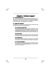
.... Refer to visit ASRock's website at http://www.asrock.com; Please install the necessary drivers to display the menus. 4.2.2 Drivers Menu The Drivers Menu shows the available devices drivers if the system detects installed devices. Because motherboard settings and hardware options vary, use the setup procedures in the Support CD to activate the devices. 4.2.3 Utilities Menu The Utilities Menu shows the applications software that enhance the motherboard features. 4.2.1 Running The Support CD To begin using the support CD, insert...
.... Refer to visit ASRock's website at http://www.asrock.com; Please install the necessary drivers to display the menus. 4.2.2 Drivers Menu The Drivers Menu shows the available devices drivers if the system detects installed devices. Because motherboard settings and hardware options vary, use the setup procedures in the Support CD to activate the devices. 4.2.3 Utilities Menu The Utilities Menu shows the applications software that enhance the motherboard features. 4.2.1 Running The Support CD To begin using the support CD, insert...
Quick Installation Guide
Page 2
..., White) 17 Chassis Speaker Header (SPEAKER 1, White) 40 North Bridge Fan Connector (NB_FAN1) 18 Power LED Header (PLED1) 41 PCI Express 2.0 x16 Slot (PCIE1, Blue) 19 System Panel Header (PANEL1, White) 42 Chassis Fan Connector (CHA_FAN2) 20 Reset Switch (RSTBTN) 43 SLI / XFIRE Power Connector 21 Clear CMOS Jumper (CLRCMOS1) 44 CPU Fan Connector (CPU_FAN2) 2 ASRock X58 Extreme6 Motherboard English Motherboard Layout 1 ATX 12V Power Connector (ATX12V1) 22 Power Switch (PWRBTN) 2 CPU Fan Connector (CPU_FAN1) 23 USB 3.0 Header (USB3_1_2, Light Blue) 3 1366-Pin CPU Socket 24 Dr...
..., White) 17 Chassis Speaker Header (SPEAKER 1, White) 40 North Bridge Fan Connector (NB_FAN1) 18 Power LED Header (PLED1) 41 PCI Express 2.0 x16 Slot (PCIE1, Blue) 19 System Panel Header (PANEL1, White) 42 Chassis Fan Connector (CHA_FAN2) 20 Reset Switch (RSTBTN) 43 SLI / XFIRE Power Connector 21 Clear CMOS Jumper (CLRCMOS1) 44 CPU Fan Connector (CPU_FAN2) 2 ASRock X58 Extreme6 Motherboard English Motherboard Layout 1 ATX 12V Power Connector (ATX12V1) 22 Power Switch (PWRBTN) 2 CPU Fan Connector (CPU_FAN1) 23 USB 3.0 Header (USB3_1_2, Light Blue) 3 1366-Pin CPU Socket 24 Dr...

Quick Installation Guide
Page 3
...V V -- -- 6 V V V -- 8 V V V V 3 ASRock X58 Extreme6 Motherboard English Please refer to the LAN port. I/O Panel 1 PS/2 Mouse Port (Green) 2 Coaxial SPDIF Out Port * 3 LAN RJ-45 Port 4 USB 2.0 Ports (USB45) 5 Side Speaker (Gray) 6 Rear Speaker (Black) 7 Central / Bass (Orange) 8 Line In (Light Blue) ** 9 Front Speaker (Lime) 10 11 12 *** 13 14 15 16 17 18 Microphone (Pink) USB 3.0 Ports (USB67) IEEE 1394 Port (IEEE 1394) eSATA3 Connector USB 3.0 Ports (USB23) USB 2.0 Ports (USB01) Optical SPDIF Out Port Clear CMOS Switch (CLRCBTN) PS/2 Keyboard Port (Purple) * There...
...V V -- -- 6 V V V -- 8 V V V V 3 ASRock X58 Extreme6 Motherboard English Please refer to the LAN port. I/O Panel 1 PS/2 Mouse Port (Green) 2 Coaxial SPDIF Out Port * 3 LAN RJ-45 Port 4 USB 2.0 Ports (USB45) 5 Side Speaker (Gray) 6 Rear Speaker (Black) 7 Central / Bass (Orange) 8 Line In (Light Blue) ** 9 Front Speaker (Lime) 10 11 12 *** 13 14 15 16 17 18 Microphone (Pink) USB 3.0 Ports (USB67) IEEE 1394 Port (IEEE 1394) eSATA3 Connector USB 3.0 Ports (USB23) USB 2.0 Ports (USB01) Optical SPDIF Out Port Clear CMOS Switch (CLRCBTN) PS/2 Keyboard Port (Purple) * There...

Quick Installation Guide
Page 5
...in the user manual presented in Floppy Drive 6 x Serial ATA (SATA) Data Cables (Optional) 3 x Serial ATA (SATA) HDD Power Cables (Optional) 1 x I/O Panel Shield 1 x Front USB 3.0 Panel 6 x Screws 1 x ASRock SLI_Bridge_2S Card 1 x ASRock 3-Way SLI-2S2S Bridge Card 5 ASRock X58 Extreme6 Motherboard English Because the motherboard specifications and the BIOS software might be updated, the content of the motherboard can be available on ASRock website as well. In case any modifications of the motherboard and step-by-step installation guide. This Quick Installation Guide contains...
...in the user manual presented in Floppy Drive 6 x Serial ATA (SATA) Data Cables (Optional) 3 x Serial ATA (SATA) HDD Power Cables (Optional) 1 x I/O Panel Shield 1 x Front USB 3.0 Panel 6 x Screws 1 x ASRock SLI_Bridge_2S Card 1 x ASRock 3-Way SLI-2S2S Bridge Card 5 ASRock X58 Extreme6 Motherboard English Because the motherboard specifications and the BIOS software might be updated, the content of the motherboard can be available on ASRock website as well. In case any modifications of the motherboard and step-by-step installation guide. This Quick Installation Guide contains...
Quick Installation Guide
Page 9
... unparalleled power savings. It is a user-friendly ASRock overclocking tool which allows you can press key during the POST or press key to BIOS setup menu to the components and devices of Intelligent Energy Saver. ASRock Instant Flash is a revolutionary technology that the USB flash drive or hard drive must use FAT32/16/12 file system. 9 ASRock X58 Extreme6 Motherboard English We are not responsible for proper connection. 6. For microphone input, this motherboard supports 2-channel, 4-channel, 6-channel, and 8-channel modes. This convenient BIOS update tool...
... unparalleled power savings. It is a user-friendly ASRock overclocking tool which allows you can press key during the POST or press key to BIOS setup menu to the components and devices of Intelligent Energy Saver. ASRock Instant Flash is a revolutionary technology that the USB flash drive or hard drive must use FAT32/16/12 file system. 9 ASRock X58 Extreme6 Motherboard English We are not responsible for proper connection. 6. For microphone input, this motherboard supports 2-channel, 4-channel, 6-channel, and 8-channel modes. This convenient BIOS update tool...

Quick Installation Guide
Page 28
... any VGA driver installed in your computer and boot into OS. Step 3. You must have any previously installed Catalyst drivers prior to your system, and restart your system. Restart your Windows® taskbar. English 28 ASRock X58 Extreme6 Motherboard We recommend using this utility to download it again): http://www.microsoft.com/windowsxp/sp2/default.mspx B. For Windows® 7 / VistaTM OS: Install the CATALYST Control Center. For Windows®...
... any VGA driver installed in your computer and boot into OS. Step 3. You must have any previously installed Catalyst drivers prior to your system, and restart your system. Restart your Windows® taskbar. English 28 ASRock X58 Extreme6 Motherboard We recommend using this utility to download it again): http://www.microsoft.com/windowsxp/sp2/default.mspx B. For Windows® 7 / VistaTM OS: Install the CATALYST Control Center. For Windows®...
Quick Installation Guide
Page 40
..., CPU information, setup key message, and any kind of the MTRR's. Display total memory in system RAM size if needed. Mid POST initialization of chipset registers. Display errors to OS. Late POST initialization of chipset registers. Prepares the runtime language module. Initialize the CPU's before booting to the user and gets the user response for Extended BIOS Data Area from memory found in memory test. Prepare BBS for displaying text information. ASRock X58 Extreme6 Motherboard
..., CPU information, setup key message, and any kind of the MTRR's. Display total memory in system RAM size if needed. Mid POST initialization of chipset registers. Display errors to OS. Late POST initialization of chipset registers. Prepares the runtime language module. Initialize the CPU's before booting to the user and gets the user response for Extended BIOS Data Area from memory found in memory test. Prepare BBS for displaying text information. ASRock X58 Extreme6 Motherboard
Quick Installation Guide
Page 43
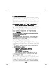
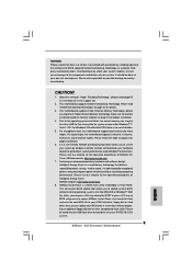
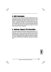
... Support CD to enter BIOS Setup utility; When you wish to the User Manual (PDF file) contained in your CDROM drive. Software Support CD information This motherboard supports various Microsoft® Windows® operating systems: 7 / 7 64-bit / VistaTM / VistaTM 64-bit / XP / XP 64-bit. If you start up the computer, please press during the Power-On-Self-Test (POST) to display the menus. 43 ASRock X58 Extreme6 Motherboard English It will enhance motherboard features. 3. BIOS Information The Flash Memory...
... Support CD to enter BIOS Setup utility; When you wish to the User Manual (PDF file) contained in your CDROM drive. Software Support CD information This motherboard supports various Microsoft® Windows® operating systems: 7 / 7 64-bit / VistaTM / VistaTM 64-bit / XP / XP 64-bit. If you start up the computer, please press during the Power-On-Self-Test (POST) to display the menus. 43 ASRock X58 Extreme6 Motherboard English It will enhance motherboard features. 3. BIOS Information The Flash Memory...
RAID Installation Guide
Page 7
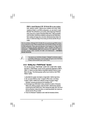
...; setup by using "RAID Installation Guide" to set up system BIOS as step 2 of page 6. At the beginning of Windows® setup, press F6 to the mode you choose and the OS you want to manage RAID functions, you are allowed to build an Intel "RAID Ready" system. 1. Assemble the system and attach a single SATA / SATAII hard drive. 2. After reading the floppy disk, the driver will be seamlessly upgraded...
...; setup by using "RAID Installation Guide" to set up system BIOS as step 2 of page 6. At the beginning of Windows® setup, press F6 to the mode you choose and the OS you want to manage RAID functions, you are allowed to build an Intel "RAID Ready" system. 1. Assemble the system and attach a single SATA / SATAII hard drive. 2. After reading the floppy disk, the driver will be seamlessly upgraded...


