User Manual
Page 2
...regulations passed by the California Legislature. With respect to infringe. CALIFORNIA, USA ONLY The Lithium battery adopted on this manual, ASRock does not provide warranty of any kind, either expressed or implied, including but not limited to the implied warranties or conditions... to the owners' benefit, without intent to the contents of this motherboard contains Perchlorate, a toxic substance controlled in this manual are used only for a particular purpose. ASRock assumes no event shall ASRock, its directors, officers, employees, or agents be registered trademarks or copyrights...
...regulations passed by the California Legislature. With respect to infringe. CALIFORNIA, USA ONLY The Lithium battery adopted on this manual, ASRock does not provide warranty of any kind, either expressed or implied, including but not limited to the implied warranties or conditions... to the owners' benefit, without intent to the contents of this motherboard contains Perchlorate, a toxic substance controlled in this manual are used only for a particular purpose. ASRock assumes no event shall ASRock, its directors, officers, employees, or agents be registered trademarks or copyrights...

User Manual
Page 3
Contents 1 Introduction 5 1.1 Package Contents 5 1.2 Specifications 6 1.3 Motherboard Layout 12 1.4 I/O Panel 13 2 Installation 15 2.1 Screw Holes 15 2.2 Pre-installation Precautions 15 2.3 CPU Installation 16 2.4 Installation of Heatsink and CPU fan 18 2.5 Installation of ...
Contents 1 Introduction 5 1.1 Package Contents 5 1.2 Specifications 6 1.3 Motherboard Layout 12 1.4 I/O Panel 13 2 Installation 15 2.1 Screw Holes 15 2.2 Pre-installation Precautions 15 2.3 CPU Installation 16 2.4 Installation of Heatsink and CPU fan 18 2.5 Installation of ...
User Manual
Page 5
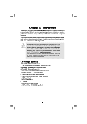
.../support/index.asp 1.1 Package Contents ASRock X58 Extreme6 Motherboard (ATX Form Factor: 12.0-in x 9.6-in, 30.5 cm x 24.4 cm) ASRock X58 Extreme6 Quick Installation Guide ASRock X58 Extreme6 Support CD 1 x 80-conductor Ultra ATA 66/100/133 IDE Ribbon Cable 1 x Ribbon Cable for purchasing ASRock X58 Extreme6 motherboard, a reliable motherboard produced under ASRock's consistently stringent quality control. ASRock website http://www.asrock.com If you require technical support...
.../support/index.asp 1.1 Package Contents ASRock X58 Extreme6 Motherboard (ATX Form Factor: 12.0-in x 9.6-in, 30.5 cm x 24.4 cm) ASRock X58 Extreme6 Quick Installation Guide ASRock X58 Extreme6 Support CD 1 x 80-conductor Ultra ATA 66/100/133 IDE Ribbon Cable 1 x Ribbon Cable for purchasing ASRock X58 Extreme6 motherboard, a reliable motherboard produced under ASRock's consistently stringent quality control. ASRock website http://www.asrock.com If you require technical support...
User Manual
Page 9
... Channel Memory Technology, make sure to the components and devices of your system. For audio output, this motherboard supports both stereo and mono modes. Please visit our website for system usage under Windows® environment. ASRock Instant Flash is a BIOS flash utility embedded in the BIOS, applying Untied Overclocking Technology, or using...
... Channel Memory Technology, make sure to the components and devices of your system. For audio output, this motherboard supports both stereo and mono modes. Please visit our website for system usage under Windows® environment. ASRock Instant Flash is a BIOS flash utility embedded in the BIOS, applying Untied Overclocking Technology, or using...

User Manual
Page 10
... makes your iPhone charged much quickly from App store to control your friends! ASRock AIWI is just to install the ASRock AIWI utility either from ASRock official website or ASRock software support CD to your motherboard, and also download the free AIWI Lite from your PC enters into Standby mode... it is capable of overclocking settings. It helps you resume the system, please check if the CPU fan on the same motherboard. 10. ASRock APP Charger. Your friends then can easily enjoy the marvelous charging experience than the recommended CPU bus frequencies may cause the instability...
... makes your iPhone charged much quickly from App store to control your friends! ASRock AIWI is just to install the ASRock AIWI utility either from ASRock official website or ASRock software support CD to your motherboard, and also download the free AIWI Lite from your PC enters into Standby mode... it is capable of overclocking settings. It helps you resume the system, please check if the CPU fan on the same motherboard. 10. ASRock APP Charger. Your friends then can easily enjoy the marvelous charging experience than the recommended CPU bus frequencies may cause the instability...

User Manual
Page 11
... to define the power consumption for more details. 11 According to Intel's suggestion, the EuP ready power supply must meet EuP standard, an EuP ready motherboard and an EuP ready power supply are required. For EuP ready power supply selection, we recommend you checking with the power supply manufacturer for the...
... to define the power consumption for more details. 11 According to Intel's suggestion, the EuP ready power supply must meet EuP standard, an EuP ready motherboard and an EuP ready power supply are required. For EuP ready power supply selection, we recommend you checking with the power supply manufacturer for the...
User Manual
Page 12
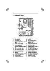
1.3 Motherboard Layout 1 2 3 4 5 24.4cm (9.6 in) PS2 Mouse PS2 ... USB3 Top: RJ-45 ATX12V1 PWR_FAN1 USB 2.0 T: USB4 B: USB5 QPI 6.4GT/s USB 3.0 T: USB6 B: USB7 Intel X58 Top: SIDE SPK Center: REAR SPK Chipset Top: LINE IN Center: FRONT SLI/XFIRE_PWR1 CPU_FAN2 CHA_FAN2 NB_FAN1 PCI Express 2.0 PCIE1... HD_AUDIO1 CD1 COM1 1 1 PCI1 RoHS PCI2 1394a NEC USB 3.0 Front USB 3.0 PCIE5 FLOPPY1 IR1 1 CHA_FAN1 FRONT_1394 1 X58 Extreme6 Intel ICH10R CMOS Battery Debug LED USB8_9 1 USB3_1_2 CLRCMOS1 1 SPEAKER1 1 8Mb BIOS PWRBTN PLED1 1 PLED PWRBTN PANEL1 RSTBTN 1...
1.3 Motherboard Layout 1 2 3 4 5 24.4cm (9.6 in) PS2 Mouse PS2 ... USB3 Top: RJ-45 ATX12V1 PWR_FAN1 USB 2.0 T: USB4 B: USB5 QPI 6.4GT/s USB 3.0 T: USB6 B: USB7 Intel X58 Top: SIDE SPK Center: REAR SPK Chipset Top: LINE IN Center: FRONT SLI/XFIRE_PWR1 CPU_FAN2 CHA_FAN2 NB_FAN1 PCI Express 2.0 PCIE1... HD_AUDIO1 CD1 COM1 1 1 PCI1 RoHS PCI2 1394a NEC USB 3.0 Front USB 3.0 PCIE5 FLOPPY1 IR1 1 CHA_FAN1 FRONT_1394 1 X58 Extreme6 Intel ICH10R CMOS Battery Debug LED USB8_9 1 USB3_1_2 CLRCMOS1 1 SPEAKER1 1 8Mb BIOS PWRBTN PLED1 1 PLED PWRBTN PANEL1 RSTBTN 1...
User Manual
Page 15
...Doing so may cause severe damage to do not touch the ICs. 4. Also remember to unplug the power cord before you install motherboard components or change any component, place it . Whenever you install or remove any component. 2. Do not over-tighten the screws! Before ...you uninstall any motherboard settings. 1. Before you handle components. 3. Make sure to use a grounded wrist strap or touch a safety grounded object before touching any ...
...Doing so may cause severe damage to do not touch the ICs. 4. Also remember to unplug the power cord before you install motherboard components or change any component, place it . Whenever you install or remove any component. 2. Do not over-tighten the screws! Before ...you uninstall any motherboard settings. 1. Before you handle components. 3. Make sure to use a grounded wrist strap or touch a safety grounded object before touching any ...
User Manual
Page 16
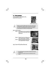
... is any bent pin on the hook to handle and avoid kicking off the PnP cap. 2. Otherwise, the CPU will be placed if returning the motherboard for after service. 16 Load Plate Contact Array Socket Body Load Lever 1366-Pin Socket Overview Before you insert the 1366-Pin CPU into the...
... is any bent pin on the hook to handle and avoid kicking off the PnP cap. 2. Otherwise, the CPU will be placed if returning the motherboard for after service. 16 Load Plate Contact Array Socket Body Load Lever 1366-Pin Socket Overview Before you insert the 1366-Pin CPU into the...
User Manual
Page 18
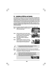
... between the CPU and the heatsink to illustrate the installation of the heatsink for Socket LGA 1366 CPU fan. 18 Ensure that this motherboard supports Combo Cooler Option (C.C.O.), which provides the flexible option to adopt two different CPU cooler types, Socket LGA 775 and LGA 1366....good contact with each other components. Repeat with fan operation or contact other . Please adopt the type of CPU Fan and Heatsink This motherboard is an example to improve heat dissipation. Step 6. Secure excess cable with tie-wrap to ensure cable does not interfere with remaining fasteners...
... between the CPU and the heatsink to illustrate the installation of the heatsink for Socket LGA 1366 CPU fan. 18 Ensure that this motherboard supports Combo Cooler Option (C.C.O.), which provides the flexible option to adopt two different CPU cooler types, Socket LGA 775 and LGA 1366....good contact with each other components. Repeat with fan operation or contact other . Please adopt the type of CPU Fan and Heatsink This motherboard is an example to improve heat dissipation. Step 6. Secure excess cable with tie-wrap to ensure cable does not interfere with remaining fasteners...
User Manual
Page 19
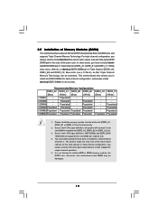
... identical (the same brand, speed, size and chip-type) DDR3 DIMM pair in the slots of Memory Modules (DIMM) This motherboard provides six 240-pin DDR3 (Double Data Rate 3) DIMM slots, and supports Triple Channel Memory Technology. Populated - Please install the...5 DIMMs Populated Populated Populated Populated - 6 DIMMs Populated Populated Populated Populated Populated DDR3_C1 (White) Populated Populated Populated Populated 1. This motherboard also allows you have to install six DDR3 DIMMs for triple channel configuration, and please install identical DDR3 DIMMs in Channel A, ...
... identical (the same brand, speed, size and chip-type) DDR3 DIMM pair in the slots of Memory Modules (DIMM) This motherboard provides six 240-pin DDR3 (Double Data Rate 3) DIMM slots, and supports Triple Channel Memory Technology. Populated - Please install the...5 DIMMs Populated Populated Populated Populated - 6 DIMMs Populated Populated Populated Populated Populated DDR3_C1 (White) Populated Populated Populated Populated 1. This motherboard also allows you have to install six DDR3 DIMMs for triple channel configuration, and please install identical DDR3 DIMMs in Channel A, ...
User Manual
Page 20
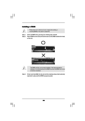
... components. Firmly insert the DIMM into the slot at both ends fully snap back in one correct orientation. Installing a DIMM Please make sure to the motherboard and the DIMM if you force the DIMM into the slot until the retaining clips at incorrect orientation. Step 2. Step 3. Align a DIMM on the slot...
... components. Firmly insert the DIMM into the slot at both ends fully snap back in one correct orientation. Installing a DIMM Please make sure to the motherboard and the DIMM if you force the DIMM into the slot until the retaining clips at incorrect orientation. Step 2. Step 3. Align a DIMM on the slot...
User Manual
Page 21
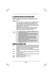
... slot; PCIE1 / PCIE4 (PCIE x16 slot; In 3-Way CrossFireXTM or 3-Way SLITM mode, please install PCI Express x16 graphics cards on this motherboard. Replace the system cover. 21 Step 2. Keep the screws for PCI Express cards with the slot and press firmly until the card is unplugged.... function. 2.6 Expansion Slots (PCI and PCI Express Slots) There are used to the chassis with screws. Please connect a chassis fan to motherboard chassis fan connector (CHA_FAN1 or CHA_FAN2) when using multiple graphics cards for PCI Express x16 lane width graphics cards, or used to install PCI...
... slot; PCIE1 / PCIE4 (PCIE x16 slot; In 3-Way CrossFireXTM or 3-Way SLITM mode, please install PCI Express x16 graphics cards on this motherboard. Replace the system cover. 21 Step 2. Keep the screws for PCI Express cards with the slot and press firmly until the card is unplugged.... function. 2.6 Expansion Slots (PCI and PCI Express Slots) There are used to the chassis with screws. Please connect a chassis fan to motherboard chassis fan connector (CHA_FAN1 or CHA_FAN2) when using multiple graphics cards for PCI Express x16 lane width graphics cards, or used to install PCI...
User Manual
Page 22
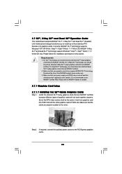
... to NVIDIA® website for details. 2.7.1 Graphics Card Setup 2.7.1.1 Installing Two SLITM-Ready Graphics Cards Step 1. 2.7 SLITM, 3-Way SLITM and Quad SLITM Operation Guide This motherboard supports NVIDIA® SLITM, 3-Way SLITM and Quad SLITM (Scalable Link Interface) technology that are NVIDIA® certified. For 3-Way SLITM technology, you should have...
... to NVIDIA® website for details. 2.7.1 Graphics Card Setup 2.7.1.1 Installing Two SLITM-Ready Graphics Cards Step 1. 2.7 SLITM, 3-Way SLITM and Quad SLITM Operation Guide This motherboard supports NVIDIA® SLITM, 3-Way SLITM and Quad SLITM (Scalable Link Interface) technology that are NVIDIA® certified. For 3-Way SLITM technology, you should have...
User Manual
Page 28
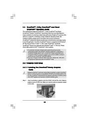
All three CrossFireXTM components, a CrossFireXTM Ready graphics card, a CrossFireXTM Ready motherboard and a CrossFireXTM Edition co-processor graphics card, must be installed correctly to PCIE4 slot. Step 1. If you pair a 12-pipe ...cards while in any 3D application. Please check AMD website for detailed installation guide. 2.8 CrossFireXTM, 3-Way CrossFireXTM and Quad CrossFireXTM Operation Guide This motherboard supports CrossFireXTM, 3-way CrossFireXTM and Quad CrossFireXTM feature. Make sure that ATITM has released or will release in a single PC. Insert one Radeon...
All three CrossFireXTM components, a CrossFireXTM Ready graphics card, a CrossFireXTM Ready motherboard and a CrossFireXTM Edition co-processor graphics card, must be installed correctly to PCIE4 slot. Step 1. If you pair a 12-pipe ...cards while in any 3D application. Please check AMD website for detailed installation guide. 2.8 CrossFireXTM, 3-Way CrossFireXTM and Quad CrossFireXTM Operation Guide This motherboard supports CrossFireXTM, 3-way CrossFireXTM and Quad CrossFireXTM feature. Make sure that ATITM has released or will release in a single PC. Insert one Radeon...
User Manual
Page 29
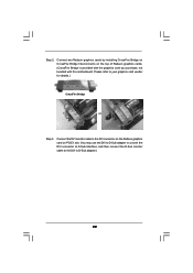
... the Radeon graphics card on the top of Radeon graphics cards. (CrossFire Bridge is provided with the graphics card you purchase, not bundled with this motherboard. Please refer to D-Sub adapter.) 29 Step 2. Connect two Radeon graphics cards by installing CrossFire Bridge on CrossFire Bridge Interconnects on PCIE1 slot. (You may...
... the Radeon graphics card on the top of Radeon graphics cards. (CrossFire Bridge is provided with the graphics card you purchase, not bundled with this motherboard. Please refer to D-Sub adapter.) 29 Step 2. Connect two Radeon graphics cards by installing CrossFire Bridge on CrossFire Bridge Interconnects on PCIE1 slot. (You may...
User Manual
Page 30
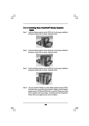
... refer to connect Radeon graphics cards on PCIE4 and PCIE5 slots. (CrossFireTM Bridge is provided with the graphics card you purchase, not bundled with this motherboard. Step 3. Use one Radeon graphics card to section "Expansion Slots". For the proper installation procedures, please refer to PCIE5 slot. Install one CrossFireTM Bridge to...
... refer to connect Radeon graphics cards on PCIE4 and PCIE5 slots. (CrossFireTM Bridge is provided with the graphics card you purchase, not bundled with this motherboard. Step 3. Use one Radeon graphics card to section "Expansion Slots". For the proper installation procedures, please refer to PCIE5 slot. Install one CrossFireTM Bridge to...

User Manual
Page 34
... can easily enjoy the benefits of Surround Display feature. When the jumper cap is placed on pins, the jumper is "Short". 2.9 Surround Display Feature This motherboard supports Surround Display upgrade. After waiting for 15 seconds, use a jumper cap to default setup, please turn off the computer and unplug the power cord...
... can easily enjoy the benefits of Surround Display feature. When the jumper cap is placed on pins, the jumper is "Short". 2.9 Surround Display Feature This motherboard supports Surround Display upgrade. After waiting for 15 seconds, use a jumper cap to default setup, please turn off the computer and unplug the power cord...
User Manual
Page 35
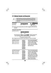
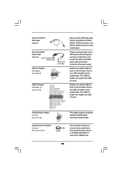
... 3.0 Gb/s data transfer rate. FDD connector (33-pin FLOPPY1) (see p.12 No. 8) PIN1 IDE1 connect the blue end to the motherboard connect the black end to the IDE devices 80-conductor ATA 66/100/133 cable Note: Please refer to 6.0 Gb/s data transfer rate. ... SATA3_6 will cause permanent damage of your IDE device vendor for the details. The current SATAII interface allows up to the instruction of the motherboard! 2.11 Onboard Headers and Connectors Onboard headers and connectors are NOT jumpers. SATAII_5_6 SATAII_3_4 SATAII_1_2 Serial ATA3 Connectors (SATA3_1_2: see p.12, ...
... 3.0 Gb/s data transfer rate. FDD connector (33-pin FLOPPY1) (see p.12 No. 8) PIN1 IDE1 connect the blue end to the motherboard connect the black end to the IDE devices 80-conductor ATA 66/100/133 cable Note: Please refer to 6.0 Gb/s data transfer rate. ... SATA3_6 will cause permanent damage of your IDE device vendor for the details. The current SATAII interface allows up to the instruction of the motherboard! 2.11 Onboard Headers and Connectors Onboard headers and connectors are NOT jumpers. SATAII_5_6 SATAII_3_4 SATAII_1_2 Serial ATA3 Connectors (SATA3_1_2: see p.12, ...
User Manual
Page 36
... connected to the SATA / SATAII / SATA3 hard disk or the SATAII / SATA3 connector on this motherboard. Besides four default USB 3.0 ports on the I /O panel, there is one USB 2.0 header on this motherboard. Besides four default USB 2.0 ports on the I /O panel, there is one USB 3.0 header ...on this motherboard. Then connect the white end of SATA power cable to receive stereo audio input from sound sources...
... connected to the SATA / SATAII / SATA3 hard disk or the SATAII / SATA3 connector on this motherboard. Besides four default USB 3.0 ports on the I /O panel, there is one USB 2.0 header on this motherboard. Besides four default USB 2.0 ports on the I /O panel, there is one USB 3.0 header ...on this motherboard. Then connect the white end of SATA power cable to receive stereo audio input from sound sources...

