
User Manual
Page 4
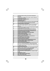
... RAID Functions 53 2.21.2 Installing Windows® 7 / 7 64-bit / VistaTM / VistaTM 64-bit Without RAID Functions 54 2.22 Untied Overclocking Technology 54 3 BIOS SETUP UTILITY 55 3.1 Introduction 55 3.1.1 BIOS Menu Bar 55 3.1.2 Navigation Keys 56 3.2 Main Screen 56 3.3 OC Tweaker Screen 57 3.4 Advanced Screen 61 3.4.1 CPU Configuration 62 3.4.2 Chipset Configuration 64 3.4.3 ACPI...
... RAID Functions 53 2.21.2 Installing Windows® 7 / 7 64-bit / VistaTM / VistaTM 64-bit Without RAID Functions 54 2.22 Untied Overclocking Technology 54 3 BIOS SETUP UTILITY 55 3.1 Introduction 55 3.1.1 BIOS Menu Bar 55 3.1.2 Navigation Keys 56 3.2 Main Screen 56 3.3 OC Tweaker Screen 57 3.4 Advanced Screen 61 3.4.1 CPU Configuration 62 3.4.2 Chipset Configuration 64 3.4.3 ACPI...
User Manual
Page 5
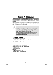
... BIOS software might be updated, the content of this motherboard, please visit our website for a 3.5-in , 30.5 cm x 24.4 cm) ASRock X58 Extreme6 Quick Installation Guide ASRock X58 Extreme6 Support CD 1 x 80-conductor Ultra ATA 66/100/133 IDE Ribbon Cable 1 x Ribbon Cable for specific information about the model you for purchasing ASRock X58 Extreme6 motherboard, a reliable motherboard produced under ASRock...
... BIOS software might be updated, the content of this motherboard, please visit our website for a 3.5-in , 30.5 cm x 24.4 cm) ASRock X58 Extreme6 Quick Installation Guide ASRock X58 Extreme6 Support CD 1 x 80-conductor Ultra ATA 66/100/133 IDE Ribbon Cable 1 x Ribbon Cable for specific information about the model you for purchasing ASRock X58 Extreme6 motherboard, a reliable motherboard produced under ASRock...

User Manual
Page 8
... Control - Microsoft® Windows® 7 / 7 64-bit / VistaTM / VistaTM 64-bit / XP / XP 64-bit compliant Certifications - Instant Boot - ASRock Instant Flash (see CAUTION 11) - ASRock APP Charger (see CAUTION 8) - AMI Legal BIOS - Supports "Plug and Play" - OEM and Trial) Unique Feature - CPU Temperature Sensing Monitor - CPU Quiet Fan - Voltage Monitoring: +12V, +5V...
... Control - Microsoft® Windows® 7 / 7 64-bit / VistaTM / VistaTM 64-bit / XP / XP 64-bit compliant Certifications - Instant Boot - ASRock Instant Flash (see CAUTION 11) - ASRock APP Charger (see CAUTION 8) - AMI Legal BIOS - Supports "Plug and Play" - OEM and Trial) Unique Feature - CPU Temperature Sensing Monitor - CPU Quiet Fan - Voltage Monitoring: +12V, +5V...
User Manual
Page 9
...power saving and improve power efficiency without entering operating systems first like MS-DOS or Windows®. ASRock Instant Flash is a BIOS flash utility embedded in the BIOS, applying Untied Overclocking Technology, or using the thirdparty overclocking tools. We are not responsible for ...motherboard supports Triple Channel Memory Technology. ASRock website: http://www.asrock.com 7. Overclocking may be less than 4GB for the reservation for details. 3. It is a user-friendly ASRock overclocking tool which allows you can update your BIOS only in a few clicks without preparing...
...power saving and improve power efficiency without entering operating systems first like MS-DOS or Windows®. ASRock Instant Flash is a BIOS flash utility embedded in the BIOS, applying Untied Overclocking Technology, or using the thirdparty overclocking tools. We are not responsible for ...motherboard supports Triple Channel Memory Technology. ASRock website: http://www.asrock.com 7. Overclocking may be less than 4GB for the reservation for details. 3. It is a user-friendly ASRock overclocking tool which allows you can update your BIOS only in a few clicks without preparing...
User Manual
Page 12
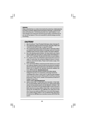
...USB 3.0 T: USB2 B: USB3 Top: RJ-45 ATX12V1 PWR_FAN1 USB 2.0 T: USB4 B: USB5 QPI 6.4GT/s USB 3.0 T: USB6 B: USB7 Intel X58 Top: SIDE SPK Center: REAR SPK Chipset Top: LINE IN Center: FRONT SLI/XFIRE_PWR1 CPU_FAN2 CHA_FAN2 NB_FAN1 PCI Express 2.0 PCIE1 IDE1 SATA3 6Gb/s SATAII_5_6 ... COM1 1 1 PCI1 RoHS PCI2 1394a NEC USB 3.0 Front USB 3.0 PCIE5 FLOPPY1 IR1 1 CHA_FAN1 FRONT_1394 1 X58 Extreme6 Intel ICH10R CMOS Battery Debug LED USB8_9 1 USB3_1_2 CLRCMOS1 1 SPEAKER1 1 8Mb BIOS PWRBTN PLED1 1 PLED PWRBTN PANEL1 RSTBTN 1 HDLED RESET 7 8 9 10 11 12 13 14 15 16...
...USB 3.0 T: USB2 B: USB3 Top: RJ-45 ATX12V1 PWR_FAN1 USB 2.0 T: USB4 B: USB5 QPI 6.4GT/s USB 3.0 T: USB6 B: USB7 Intel X58 Top: SIDE SPK Center: REAR SPK Chipset Top: LINE IN Center: FRONT SLI/XFIRE_PWR1 CPU_FAN2 CHA_FAN2 NB_FAN1 PCI Express 2.0 PCIE1 IDE1 SATA3 6Gb/s SATAII_5_6 ... COM1 1 1 PCI1 RoHS PCI2 1394a NEC USB 3.0 Front USB 3.0 PCIE5 FLOPPY1 IR1 1 CHA_FAN1 FRONT_1394 1 X58 Extreme6 Intel ICH10R CMOS Battery Debug LED USB8_9 1 USB3_1_2 CLRCMOS1 1 SPEAKER1 1 8Mb BIOS PWRBTN PLED1 1 PLED PWRBTN PANEL1 RSTBTN 1 HDLED RESET 7 8 9 10 11 12 13 14 15 16...

User Manual
Page 34
... right after you can easily enjoy the benefits of Surround Display feature. If you need to clear the CMOS when you just finish updating the BIOS, you must boot up the system first, and then shut it down before you to the document at the following path in the Support CD... setup. The data in CMOS. When the jumper cap is placed on pins, the jumper is placed on PCI Express VGA cards, you update the BIOS.
... right after you can easily enjoy the benefits of Surround Display feature. If you need to clear the CMOS when you just finish updating the BIOS, you must boot up the system first, and then shut it down before you to the document at the following path in the Support CD... setup. The data in CMOS. When the jumper cap is placed on pins, the jumper is placed on PCI Express VGA cards, you update the BIOS.

User Manual
Page 42
... D1 D1 D0 D2 D3 D4 D5 D6 D7 D8 D9 DA Description Early chipset initialization is used to checkpoint E0. Determine whether to BIOS POST (ExecutePOSTKernel). 42 Store the Uncompressed pointer for reading the Dr. Debug codes. Give control to execute serial flash. Early super I/O ...checkpoints that may occur during the bootblock initialization portion of RAM. Adjust policies and cache first 8MB. Bootblock code is given to determine if BIOS recovery is disabled. Restore CPUID value back into memory. Leaves all RAM below for future use in memory. 2.13 Dr. Debug Dr...
... D1 D1 D0 D2 D3 D4 D5 D6 D7 D8 D9 DA Description Early chipset initialization is used to checkpoint E0. Determine whether to BIOS POST (ExecutePOSTKernel). 42 Store the Uncompressed pointer for reading the Dr. Debug codes. Give control to execute serial flash. Early super I/O ...checkpoints that may occur during the bootblock initialization portion of RAM. Adjust policies and cache first 8MB. Bootblock code is given to determine if BIOS recovery is disabled. Restore CPUID value back into memory. Leaves all RAM below for future use in memory. 2.13 Dr. Debug Dr...

User Manual
Page 43
...Init Local APIC Set up boot strap proccessor Information Set up application proccessors Re-enable cache for initialization. See DIM Code Checkpoints section of the BIOS: Checkpoint 03 04 05 06 08 C0 C1 C2 C5 C6 C7 0A 0B 0C 0E 13 24 30 2A 2C 2E 31 Description Disable... Runtime data area. Traps INT1Ch vector to CH-2 count reg. Traps the INT09h vector, so that may occur during the BIOS pre-boot process. Uncompress and initialize any platform specific BIOS modules. Enable IRQ-0 in KBC port. Allocate memory for ADM. The following table describes the type of checkpoints that the ...
...Init Local APIC Set up boot strap proccessor Information Set up application proccessors Re-enable cache for initialization. See DIM Code Checkpoints section of the BIOS: Checkpoint 03 04 05 06 08 C0 C1 C2 C5 C6 C7 0A 0B 0C 0E 13 24 30 2A 2C 2E 31 Description Disable... Runtime data area. Traps INT1Ch vector to CH-2 count reg. Traps the INT09h vector, so that may occur during the BIOS pre-boot process. Uncompress and initialize any platform specific BIOS modules. Enable IRQ-0 in KBC port. Allocate memory for ADM. The following table describes the type of checkpoints that the ...
User Manual
Page 44
...ACPI. 00 Passes control to limit memory test. Enable/Disable NMI as selected 90 Late POST initialization of runtime image preparation for different BIOS modules. Fill the free area in NVRam. 84 Log errors encountered during POST. 85 Display errors to OS. A7 Displays the ...config display if needed / requested. 8C Late POST initialization of ESCD in F000h segment with 0FFh. A9 Wait for error. 87 Execute BIOS setup if needed . A2 Takes care of system management interrupt. Disables the system configuration display if needed before boot, which includes the ...
...ACPI. 00 Passes control to limit memory test. Enable/Disable NMI as selected 90 Late POST initialization of runtime image preparation for different BIOS modules. Fill the free area in NVRam. 84 Log errors encountered during POST. 85 Display errors to OS. A7 Displays the ...config display if needed / requested. 8C Late POST initialization of ESCD in F000h segment with 0FFh. A9 Wait for error. 87 Execute BIOS setup if needed . A2 Takes care of system management interrupt. Disables the system configuration display if needed before boot, which includes the ...
User Manual
Page 49
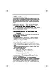
...install can be auto-detected and listed on your SATA / SATAII HDDs with RAID functions, please follow the order from up BIOS. 2.19 Driver Installation Guide To install the drivers to your system, please insert the support CD to your system. A. D. Enter... BIOS SETUP UTILITY Advanced screen Storage Configuration. B. Formatting the floppy diskette will start to configure the RAID function, you want to install Windows® 7 /...
...install can be auto-detected and listed on your SATA / SATAII HDDs with RAID functions, please follow the order from up BIOS. 2.19 Driver Installation Guide To install the drivers to your system, please insert the support CD to your system. A. D. Enter... BIOS SETUP UTILITY Advanced screen Storage Configuration. B. Formatting the floppy diskette will start to configure the RAID function, you want to install Windows® 7 /...
User Manual
Page 50
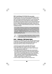
...; XP 64-bit. A "RAID Ready" system can be installed to your system. Begin Windows® setup by using "RAID Installation Guide" to set up system BIOS as step 2 of Windows® setup, press F6 to use "Intel Matrix Storage Manager" in the folder at a later date by booting from the Support...
...; XP 64-bit. A "RAID Ready" system can be installed to your system. Begin Windows® setup by using "RAID Installation Guide" to set up system BIOS as step 2 of Windows® setup, press F6 to use "Intel Matrix Storage Manager" in the folder at a later date by booting from the Support...
User Manual
Page 52
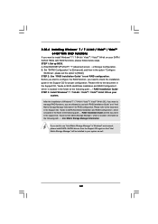
...document in the Support CD, "Guide to SATA Hard Disks Installation and RAID Configuration", which is located in the Support CD for RAID configuration. Enter BIOS SETUP UTILITY Advanced screen Storage Configuration. After the installation of Windows® 7 / 7 64-bit / VistaTM / VistaTM 64-bit OS, if...If you want to use both "RAID Installation Guide" and "Intel Matrix Storage Manager Information" for proper configuration. A. STEP 1: Set up BIOS. Please refer to the document in the Support CD, "Guide to SATA Hard Disks Installation and RAID Configuration", which is located in the ...
...document in the Support CD, "Guide to SATA Hard Disks Installation and RAID Configuration", which is located in the Support CD for RAID configuration. Enter BIOS SETUP UTILITY Advanced screen Storage Configuration. After the installation of Windows® 7 / 7 64-bit / VistaTM / VistaTM 64-bit OS, if...If you want to use both "RAID Installation Guide" and "Intel Matrix Storage Manager Information" for proper configuration. A. STEP 1: Set up BIOS. Please refer to the document in the Support CD, "Guide to SATA Hard Disks Installation and RAID Configuration", which is located in the ...

User Manual
Page 53
...STEP 3: Install Windows® XP / XP 64-bit OS on page 49. After reading the floppy disk, the driver will be presented. Enter BIOS SETUP UTILITY Advanced screen Storage Configuration. B. Set "SATAII Configuration" to [Enhanced], and then in the option "Configure SATAII as ", please set ...then in the option "Configure SATAII as ", please set the option to [AHCI]. Using SATA / SATAII HDDs with NCQ function STEP 1: Set Up BIOS. Please make a SATA / SATAII driver diskette by following section 2.20.1 step 2 on your SATA / SATAII HDDs without RAID functions, please follow below...
...STEP 3: Install Windows® XP / XP 64-bit OS on page 49. After reading the floppy disk, the driver will be presented. Enter BIOS SETUP UTILITY Advanced screen Storage Configuration. B. Set "SATAII Configuration" to [Enhanced], and then in the option "Configure SATAII as ", please set ...then in the option "Configure SATAII as ", please set the option to [AHCI]. Using SATA / SATAII HDDs with NCQ function STEP 1: Set Up BIOS. Please make a SATA / SATAII driver diskette by following section 2.20.1 step 2 on your SATA / SATAII HDDs without RAID functions, please follow below...

User Manual
Page 54
... Please refer to the warning on page 9 for the possible overclocking risk before you enable Untied Overclocking function, please enter "Overclock Mode" option of BIOS setup to set the option to [IDE]. A. STEP 2: Install Windows® 7 / 7 64-bit / VistaTM / VistaTM 64-bit OS ...to [Manual]. Using SATA / SATAII HDDs with NCQ function STEP 1: Set Up BIOS. Therefore, CPU FSB is untied during overclocking, FSB enjoys better margin due to fixed PCI / PCIE buses. Enter BIOS SETUP UTILITY Advanced screen Storage Configuration. B. Before you apply Untied Overclocking Technology. ...
... Please refer to the warning on page 9 for the possible overclocking risk before you enable Untied Overclocking function, please enter "Overclock Mode" option of BIOS setup to set the option to [IDE]. A. STEP 2: Install Windows® 7 / 7 64-bit / VistaTM / VistaTM 64-bit OS ...to [Manual]. Using SATA / SATAII HDDs with NCQ function STEP 1: Set Up BIOS. Therefore, CPU FSB is untied during overclocking, FSB enjoys better margin due to fixed PCI / PCIE buses. Enter BIOS SETUP UTILITY Advanced screen Storage Configuration. B. Before you apply Untied Overclocking Technology. ...
User Manual
Page 55
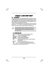
...system. You may not exactly match what you start up the security features Exit To exit the current screen or the BIOS SETUP UTILITY Use < > key or < > key to enter the BIOS SETUP UTILITY after POST, restart the system by pressing + + , or by turning the system off and then back... menu bar with its test routines. Please press or during the Power-On-Self-Test (POST) to enter the BIOS SETUP UTILITY, otherwise, POST will continue with the following BIOS setup screens and descriptions are for reference purpose only, and they may also restart by pressing the reset button on ...
...system. You may not exactly match what you start up the security features Exit To exit the current screen or the BIOS SETUP UTILITY Use < > key or < > key to enter the BIOS SETUP UTILITY after POST, restart the system by pressing + + , or by turning the system off and then back... menu bar with its test routines. Please press or during the Power-On-Self-Test (POST) to enter the BIOS SETUP UTILITY, otherwise, POST will continue with the following BIOS setup screens and descriptions are for reference purpose only, and they may also restart by pressing the reset button on ...

User Manual
Page 56
... Navigation Keys Please check the following table for all the settings To save changes and exit the BIOS SETUP UTILITY To jump to the Exit Screen or exit the current screen 3.2 Main Screen When you enter the BIOS SETUP UTILITY, the Main screen will appear and display the system overview... UTILITY Main OC Tweaker Advanced H/W Monitor Boot Security Exit System Overview System Time System Date [14:00:09] [Tue 08/03/2010] BIOS Version : X58 Extreme6 P1.00 Processor Type : Intel (R) Core (TM) i7 CPU 975 @ 3.33GHz (64bit) Processor Speed : 3333MHz Microcode Update : 106A5/11 Cache Size : ...
... Navigation Keys Please check the following table for all the settings To save changes and exit the BIOS SETUP UTILITY To jump to the Exit Screen or exit the current screen 3.2 Main Screen When you enter the BIOS SETUP UTILITY, the Main screen will appear and display the system overview... UTILITY Main OC Tweaker Advanced H/W Monitor Boot Security Exit System Overview System Time System Date [14:00:09] [Tue 08/03/2010] BIOS Version : X58 Extreme6 P1.00 Processor Type : Intel (R) Core (TM) i7 CPU 975 @ 3.33GHz (64bit) Processor Speed : 3333MHz Microcode Update : 106A5/11 Cache Size : ...

User Manual
Page 57
... this option to Sub Screen F1 General Help F9 Load Defaults F10 Save and Exit ESC Exit v02.54 (C) Copyright 1985-2005, American Megatrends, Inc. BIOS SETUP UTILITY Main OC Tweaker Advanced H/W Monitor Boot Security Exit OC Tweaker Settings Load CPU EZ OC Setting [Press Enter] Load DDR3 EZ OC Setting...
... this option to Sub Screen F1 General Help F9 Load Defaults F10 Save and Exit ESC Exit v02.54 (C) Copyright 1985-2005, American Megatrends, Inc. BIOS SETUP UTILITY Main OC Tweaker Advanced H/W Monitor Boot Security Exit OC Tweaker Settings Load CPU EZ OC Setting [Press Enter] Load DDR3 EZ OC Setting...

User Manual
Page 58
... above [3200MHz]. Configuration options: [Auto], [1600MHz], [1866MHz], [2133MHz], [2400MHz], [2666MHz], [2933MHz], [3200MHz], [3466MHz], [3733MHz], [4000MHz] and [4266MHz]. The default value is [Auto]. DRAM Timing Control BIOS SETUP UTILITY Advanced DRAM Timing Control Current Setting : 7-7-7-20-59-8-4-4-4-20 DRAM tCL [Auto] DRAM tRCD [Auto] DRAM tRP [Auto] DRAM tRAS [Auto] DRAM tRFC...
... above [3200MHz]. Configuration options: [Auto], [1600MHz], [1866MHz], [2133MHz], [2400MHz], [2666MHz], [2933MHz], [3200MHz], [3466MHz], [3733MHz], [4000MHz] and [4266MHz]. The default value is [Auto]. DRAM Timing Control BIOS SETUP UTILITY Advanced DRAM Timing Control Current Setting : 7-7-7-20-59-8-4-4-4-20 DRAM tCL [Auto] DRAM tRCD [Auto] DRAM tRP [Auto] DRAM tRAS [Auto] DRAM tRFC...

User Manual
Page 59
... options: [Auto], [2] to [15]. Configuration options : [1], [2] and [Auto]. The default value is [With VDroop]. 59 Besides the BIOS option, you want to enable this function, please set this function. The default value is [Enabled]. Configuration options: Configuration options: [Auto], ...DRAM clocks for TRCD. Configuration options: Configuration options: [Auto], [4] to [13]. DRAM Command Rate Use this to enable or disable ASRock VDroop control. Configuration options: [Enabled] and [Disabled]. DRAM tRCD This controls the number of DRAM clocks for TRRD. Configuration options:...
... options: [Auto], [2] to [15]. Configuration options : [1], [2] and [Auto]. The default value is [With VDroop]. 59 Besides the BIOS option, you want to enable this function, please set this function. The default value is [Enabled]. Configuration options: Configuration options: [Auto], ...DRAM clocks for TRCD. Configuration options: Configuration options: [Auto], [4] to [13]. DRAM Command Rate Use this to enable or disable ASRock VDroop control. Configuration options: [Enabled] and [Disabled]. DRAM tRCD This controls the number of DRAM clocks for TRRD. Configuration options:...

User Manual
Page 61
... be noted that the USB flash drive or hard drive must use FAT32/16/ 12 file system. ASRock Instant Flash ASRock Instant Flash is a BIOS flash utility embedded in below sections may set the configurations for CPU WARNING : Setting wrong values in ...USB Configuration. CPU Configuration Chipset Configuration ACPI Configuration Storage Configuration PCIPnP Configuration Floppy Configuration SuperIO Configuration USB Configuration BIOS Update Utility ASRock Instant Flash Select Screen Select Item Enter Go to malfunction. 3.4 Advanced Screen In this section, you can update your...
... be noted that the USB flash drive or hard drive must use FAT32/16/ 12 file system. ASRock Instant Flash ASRock Instant Flash is a BIOS flash utility embedded in below sections may set the configurations for CPU WARNING : Setting wrong values in ...USB Configuration. CPU Configuration Chipset Configuration ACPI Configuration Storage Configuration PCIPnP Configuration Floppy Configuration SuperIO Configuration USB Configuration BIOS Update Utility ASRock Instant Flash Select Screen Select Item Enter Go to malfunction. 3.4 Advanced Screen In this section, you can update your...


