User Manual
Page 3
...Motherboard Layout 12 1.4 I/O Panel 13 2 Installation 14 2.1 Screw Holes 14 2.2 Pre-installation Precautions 14 2.3 CPU Installation 15 2.4 Installation of Heatsink and CPU fan 17 2.5 Installation of Memory Modules (DIMM 18 2.6 Expansion Slots (PCI Express Slots 19 2.7 Dual Monitor and Surround Display Features 20 2.8 Jumpers Setup 23 2.9 Onboard Headers and Connectors 24 2.10 Serial ATA (SATA) / Serial ATAII (SATAII) Hard Disks Installation 28 2.11 Hot Plug Function for SATA / SATAII HDDs 28 2.12 SATA / SATAII HDD Hot Plug Feature and Operation Guide 29 2.13 Driver Installation...
...Motherboard Layout 12 1.4 I/O Panel 13 2 Installation 14 2.1 Screw Holes 14 2.2 Pre-installation Precautions 14 2.3 CPU Installation 15 2.4 Installation of Heatsink and CPU fan 17 2.5 Installation of Memory Modules (DIMM 18 2.6 Expansion Slots (PCI Express Slots 19 2.7 Dual Monitor and Surround Display Features 20 2.8 Jumpers Setup 23 2.9 Onboard Headers and Connectors 24 2.10 Serial ATA (SATA) / Serial ATAII (SATAII) Hard Disks Installation 28 2.11 Hot Plug Function for SATA / SATAII HDDs 28 2.12 SATA / SATAII HDD Hot Plug Feature and Operation Guide 29 2.13 Driver Installation...

User Manual
Page 6
... 3D, Intel® Clear Video HD Technology, Intel® InsiderTM, Intel® HD Graphics 2500/4000 with Intel® Ivy Bridge CPU. Max. Supports Intel® Rapid Start Technology and Smart Connect Technology - Supports Intel® Extreme Memory Profile (XMP) 1.3 / 1.2 with Intel® Ivy Bridge CPU - 1 x PCI Express 3.0 x16 slot (blue @ x16 mode) * PCIE 3.0 is only supported with Intel® Ivy Bridge CPU - Max. Solid Capacitor for CPU power - Supports K-Series unlocked CPU - Supports DDR3 1600/1333/1066...
... 3D, Intel® Clear Video HD Technology, Intel® InsiderTM, Intel® HD Graphics 2500/4000 with Intel® Ivy Bridge CPU. Max. Supports Intel® Rapid Start Technology and Smart Connect Technology - Supports Intel® Extreme Memory Profile (XMP) 1.3 / 1.2 with Intel® Ivy Bridge CPU - 1 x PCI Express 3.0 x16 slot (blue @ x16 mode) * PCIE 3.0 is only supported with Intel® Ivy Bridge CPU - Max. Solid Capacitor for CPU power - Supports K-Series unlocked CPU - Supports DDR3 1600/1333/1066...
User Manual
Page 9
... installation. 3. Before you can press key during the POST or press key to BIOS setup menu to utilize the memory that the USB flash drive or hard drive must use . 4. In IES (Intelligent Energy Saver), the voltage regulator can use ASRock XFast RAM to access ASRock Instant Flash. ASRock website: http://www.asrock.com 6. Please check Intel® website for you can load the OC profile to their own system to change. In Fan Control...
... installation. 3. Before you can press key during the POST or press key to BIOS setup menu to utilize the memory that the USB flash drive or hard drive must use . 4. In IES (Intelligent Energy Saver), the voltage regulator can use ASRock XFast RAM to access ASRock Instant Flash. ASRock website: http://www.asrock.com 6. Please check Intel® website for you can load the OC profile to their own system to change. In Fan Control...
User Manual
Page 10
... HD video and download files simultaneously. Traffic Shaping: You can boost USB storage device performance. Real-Time Analysis of Your Data: With the status window, you - ASRock XFast RAM fully utilizes the memory space that cannot be used under Windows® OS 32-bit CPU. ASRock APP Charger. SmartView, a new function of internet browser, is that it reduces the frequency of ASRock XFast RAM is the smart start...
... HD video and download files simultaneously. Traffic Shaping: You can boost USB storage device performance. Real-Time Analysis of Your Data: With the status window, you - ASRock XFast RAM fully utilizes the memory space that cannot be used under Windows® OS 32-bit CPU. ASRock APP Charger. SmartView, a new function of internet browser, is that it reduces the frequency of ASRock XFast RAM is the smart start...

User Manual
Page 12
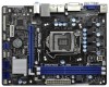
...) 13 Chassis Speaker Header (SPEAKER 1, White) 14 System Panel Header (PANEL1, White) 15 USB 2.0 Header (USB6_7, Blue) 16 USB 2.0 Header (USB8_9, Blue) 17 COM Port Header (COM1) 18 Print Port Header (LPT1, White) 19 Front Panel Audio Header (HD_AUDIO1, White) 20 PCI Express 2.0 x1 Slot (PCIE2, White) 21 Clear CMOS Jumper (CLRCMOS1) 22 PCI Express 3.0 x16 Slot (PCIE1, Blue) 23 Power Fan Connector (PWR_FAN1) 12 D G S PWR_FAN1 LAN PHY 5 22 PCIE1 Designed in ) DDR3_B1 (64 bit, 240-pin module) DDR3_A1 (64 bit, 240-pin module...
...) 13 Chassis Speaker Header (SPEAKER 1, White) 14 System Panel Header (PANEL1, White) 15 USB 2.0 Header (USB6_7, Blue) 16 USB 2.0 Header (USB8_9, Blue) 17 COM Port Header (COM1) 18 Print Port Header (LPT1, White) 19 Front Panel Audio Header (HD_AUDIO1, White) 20 PCI Express 2.0 x1 Slot (PCIE2, White) 21 Clear CMOS Jumper (CLRCMOS1) 22 PCI Express 3.0 x16 Slot (PCIE1, Blue) 23 Power Fan Connector (PWR_FAN1) 12 D G S PWR_FAN1 LAN PHY 5 22 PCIE1 Designed in ) DDR3_B1 (64 bit, 240-pin module) DDR3_A1 (64 bit, 240-pin module...

User Manual
Page 20
..., please install onboard VGA driver from our support CD to support dual VGA output so that DVI-D and D-sub can freely enjoy the benefits of dual monitor feature without installing any add-on the I/O panel. D-Sub port DVI-D port 2. 2.7 Dual Monitor and Surround Display Features Dual Monitor Feature This motherboard supports dual monitor feature. Connect DVI-D monitor cable to DVI-D port on the I/O panel, and connect D-Sub monitor cable to D-Sub port on VGA card to your system and restart your system boots.
..., please install onboard VGA driver from our support CD to support dual VGA output so that DVI-D and D-sub can freely enjoy the benefits of dual monitor feature without installing any add-on the I/O panel. D-Sub port DVI-D port 2. 2.7 Dual Monitor and Surround Display Features Dual Monitor Feature This motherboard supports dual monitor feature. Connect DVI-D monitor cable to DVI-D port on the I/O panel, and connect D-Sub monitor cable to D-Sub port on VGA card to your system and restart your system boots.

User Manual
Page 21
... steps to the corresponding connectors of surround display feature. Then connect other monitor cables to set up a multi-monitor display. Boot your primary monitor, and then select "Primary". Click the "Identify" button to enter UEFI setup. Click "Extend my Windows desktop onto this motherboard. 4. Install the PCI Express VGA card on PCI Express VGA cards, you can adjust the parameters of D-sub. B. Press or to display a large number on the I /O panel, and connect D-Sub monitor cable to your card, one , two, three...
... steps to the corresponding connectors of surround display feature. Then connect other monitor cables to set up a multi-monitor display. Boot your primary monitor, and then select "Primary". Click the "Identify" button to enter UEFI setup. Click "Extend my Windows desktop onto this motherboard. 4. Install the PCI Express VGA card on PCI Express VGA cards, you can adjust the parameters of D-sub. B. Press or to display a large number on the I /O panel, and connect D-Sub monitor cable to your card, one , two, three...

User Manual
Page 31
... install Windows® XP / XP 64-bit OS on your system. Therefore, the drivers you install can be auto-detected and listed on your optical drive first. Using SATA / SATAII HDDs with NCQ function STEP 1: Set Up UEFI. During POST at the beginning of system boot-up to bottom side to install those required drivers. A. B. Set the option "SATA Mode Selection" to format and copy files [YN]? Insert the Support...
... install Windows® XP / XP 64-bit OS on your system. Therefore, the drivers you install can be auto-detected and listed on your optical drive first. Using SATA / SATAII HDDs with NCQ function STEP 1: Set Up UEFI. During POST at the beginning of system boot-up to bottom side to install those required drivers. A. B. Set the option "SATA Mode Selection" to format and copy files [YN]? Insert the Support...

User Manual
Page 40
... [Auto]. CPU C6 State Support Use this technology, such as Microsoft® Windows® XP / VistaTM / 7 is an enhancement 40 Enhance Halt State (C1E) All processors support the Halt State (C1). Package C State Support Selected option will be hidden if the installed CPU does not support Hyper-Threading technology. Set to [Enabled] if using Microsoft® Windows® XP, VistaTM, 7, or Linux kernel version 2.4.18 or higher. No-Execute Memory...
... [Auto]. CPU C6 State Support Use this technology, such as Microsoft® Windows® XP / VistaTM / 7 is an enhancement 40 Enhance Halt State (C1E) All processors support the Halt State (C1). Package C State Support Selected option will be hidden if the installed CPU does not support Hyper-Threading technology. Set to [Enabled] if using Microsoft® Windows® XP, VistaTM, 7, or Linux kernel version 2.4.18 or higher. No-Execute Memory...

User Manual
Page 49
...legacy OS and UEFI setup when [Disabled] is selected. There are connected. [Disabled] - Enables support for the details of USB 2.0 controller. If you have USB compatibility issues, it is [Enabled]. USB devices are not allowed to below descriptions for legacy USB. [Auto] - Enables legacy support if USB devices are four configuration options: [Enabled], [Auto], [Disabled] and [UEFI Setup Only]. 3.4.9 USB Configuration USB 2.0 Controller Use this option to use under UEFI setup and Windows / Linux OS. 49 Legacy USB Support Use this item to enter OS. [UEFI Setup...
...legacy OS and UEFI setup when [Disabled] is selected. There are connected. [Disabled] - Enables support for the details of USB 2.0 controller. If you have USB compatibility issues, it is [Enabled]. USB devices are not allowed to below descriptions for legacy USB. [Auto] - Enables legacy support if USB devices are four configuration options: [Enabled], [Auto], [Disabled] and [UEFI Setup Only]. 3.4.9 USB Configuration USB 2.0 Controller Use this option to use under UEFI setup and Windows / Linux OS. 49 Legacy USB Support Use this item to enter OS. [UEFI Setup...

User Manual
Page 54
Because motherboard settings and hardware options vary, use the setup procedures in the Support CD to display the menus. 4.2.2 Drivers Menu The Drivers Menu shows the available devices drivers if the system detects installed devices. Click on the file "ASSETUP.EXE" from the BIN folder in this chapter for general reference only. If the Main Menu did not appear automatically, locate and double click on a specific item...
Because motherboard settings and hardware options vary, use the setup procedures in the Support CD to display the menus. 4.2.2 Drivers Menu The Drivers Menu shows the available devices drivers if the system detects installed devices. Click on the file "ASSETUP.EXE" from the BIN folder in this chapter for general reference only. If the Main Menu did not appear automatically, locate and double click on a specific item...

Quick Installation Guide
Page 2
...) 13 Chassis Speaker Header (SPEAKER 1, White) 14 System Panel Header (PANEL1, White) 15 USB 2.0 Header (USB6_7, Blue) 16 USB 2.0 Header (USB8_9, Blue) 17 COM Port Header (COM1) 18 Print Port Header (LPT1, White) 19 Front Panel Audio Header (HD_AUDIO1, White) 20 PCI Express 2.0 x1 Slot (PCIE2, White) 21 Clear CMOS Jumper (CLRCMOS1) 22 PCI Express 3.0 x16 Slot (PCIE1, Blue) 23 Power Fan Connector (PWR_FAN1) 2 ASRock H71M-DGS Motherboard English D G S PWR_FAN1 LAN PHY 5 22 PCIE1 Designed in ) DDR3_B1 (64 bit, 240-pin module) DDR3_A1 (64 bit, 240-pin module...
...) 13 Chassis Speaker Header (SPEAKER 1, White) 14 System Panel Header (PANEL1, White) 15 USB 2.0 Header (USB6_7, Blue) 16 USB 2.0 Header (USB8_9, Blue) 17 COM Port Header (COM1) 18 Print Port Header (LPT1, White) 19 Front Panel Audio Header (HD_AUDIO1, White) 20 PCI Express 2.0 x1 Slot (PCIE2, White) 21 Clear CMOS Jumper (CLRCMOS1) 22 PCI Express 3.0 x16 Slot (PCIE1, Blue) 23 Power Fan Connector (PWR_FAN1) 2 ASRock H71M-DGS Motherboard English D G S PWR_FAN1 LAN PHY 5 22 PCIE1 Designed in ) DDR3_B1 (64 bit, 240-pin module) DDR3_A1 (64 bit, 240-pin module...
Quick Installation Guide
Page 4
... case any modifications of the motherboard and step-bystep installation guide. Introduction Thank you are using. To get better performance in Windows® 7 / 7 64-bit / VistaTM / VistaTM 64bit, it is recommended to set the BIOS option in the Support CD. For the BIOS setup, please refer to the "User Manual" in , 22.6 cm x 17.3 cm) ASRock H71M-DGS Quick Installation Guide ASRock H71M-DGS Support CD 2 x Serial ATA (SATA) Data Cables (Optional) 1 x I/O Panel Shield ASRock Reminds You... www.asrock...
... case any modifications of the motherboard and step-bystep installation guide. Introduction Thank you are using. To get better performance in Windows® 7 / 7 64-bit / VistaTM / VistaTM 64bit, it is recommended to set the BIOS option in the Support CD. For the BIOS setup, please refer to the "User Manual" in , 22.6 cm x 17.3 cm) ASRock H71M-DGS Quick Installation Guide ASRock H71M-DGS Support CD 2 x Serial ATA (SATA) Data Cables (Optional) 1 x I/O Panel Shield ASRock Reminds You... www.asrock...

Quick Installation Guide
Page 5
...; Ivy Bridge CPU. Max. shared memory 1759MB with processors which are GPU integrated. - Max. Dual Channel DDR3 Memory Technology (see CAUTION 4) 5 ASRock H71M-DGS Motherboard English 1.2 Specifications Platform CPU Chipset Memory Expansion Slot Graphics - Micro ATX Form Factor: 8.9-in x 6.8-in LGA1155 Package - Intel® H61 - Supports Intel® Rapid Start Technology and Smart Connect Technology - Max. Supports Intel® HD Graphics Built-in Visuals: Intel® Quick Sync Video 2.0, Intel® InTruTM 3D, Intel® Clear Video HD Technology, Intel®...
...; Ivy Bridge CPU. Max. shared memory 1759MB with processors which are GPU integrated. - Max. Dual Channel DDR3 Memory Technology (see CAUTION 4) 5 ASRock H71M-DGS Motherboard English 1.2 Specifications Platform CPU Chipset Memory Expansion Slot Graphics - Micro ATX Form Factor: 8.9-in x 6.8-in LGA1155 Package - Intel® H61 - Supports Intel® Rapid Start Technology and Smart Connect Technology - Max. Supports Intel® HD Graphics Built-in Visuals: Intel® Quick Sync Video 2.0, Intel® InTruTM 3D, Intel® Clear Video HD Technology, Intel®...
Quick Installation Guide
Page 8
... settings as a profile and share with 64-bit CPU, there is subject to adjust. This convenient BIOS update tool allows you can update your friends. In OC DNA, you can press key during the POST or press key to BIOS setup menu to the operating system limitation, the actual memory size may be noted that Windows® cannot use FAT32/16/12 file system. 8 ASRock H71M-DGS Motherboard...
... settings as a profile and share with 64-bit CPU, there is subject to adjust. This convenient BIOS update tool allows you can update your friends. In OC DNA, you can press key during the POST or press key to BIOS setup menu to the operating system limitation, the actual memory size may be noted that Windows® cannot use FAT32/16/12 file system. 8 ASRock H71M-DGS Motherboard...

Quick Installation Guide
Page 9
... unplug the power cord, then plug it can be used . 9 ASRock H71M-DGS Motherboard English The performance may depend on the property of Adobe Photoshop 5 times faster. It also shortens the loading time of internet browser, is Windows® 7 / 7 64 bit / VistaTM / VistaTM 64 bit, and your PC enters into an enhanced view for IE that it reduces the frequency of accessing your application...
... unplug the power cord, then plug it can be used . 9 ASRock H71M-DGS Motherboard English The performance may depend on the property of Adobe Photoshop 5 times faster. It also shortens the loading time of internet browser, is Windows® 7 / 7 64 bit / VistaTM / VistaTM 64 bit, and your PC enters into an enhanced view for IE that it reduces the frequency of accessing your application...

Quick Installation Guide
Page 16
... 16 ASRock H71M-DGS Motherboard If you can easily enjoy the benefits of dual monitor function after your computer. To enable dual monitor feature, please follow the below steps: 1. Connect DVI-D monitor cable to your system and restart your system boots. With the internal VGA output support (DVI-D and D-Sub), you have installed onboard VGA driver from our support CD to DVI-D port on the I /O panel. 2.5 Dual Monitor and Surround Display Features Dual Monitor Feature This motherboard supports dual monitor...
... 16 ASRock H71M-DGS Motherboard If you can easily enjoy the benefits of dual monitor function after your computer. To enable dual monitor feature, please follow the below steps: 1. Connect DVI-D monitor cable to your system and restart your system boots. With the internal VGA output support (DVI-D and D-Sub), you have installed onboard VGA driver from our support CD to DVI-D port on the I /O panel. 2.5 Dual Monitor and Surround Display Features Dual Monitor Feature This motherboard supports dual monitor...

Quick Installation Guide
Page 17
... on PCI Express VGA card driver to set up a multi-monitor display. Click "Extend my Windows desktop onto this motherboard. 4. F. Click "Apply" or "OK" to enter UEFI setup. A. When you use multiple monitors with your system. D. If you select is inserted to page 15 for proper expansion card installation procedures for the diaplay icon identified by the number 2. Then connect other monitor cables to enable the function of the system memory. Boot...
... on PCI Express VGA card driver to set up a multi-monitor display. Click "Extend my Windows desktop onto this motherboard. 4. F. Click "Apply" or "OK" to enter UEFI setup. A. When you use multiple monitors with your system. D. If you select is inserted to page 15 for proper expansion card installation procedures for the diaplay icon identified by the number 2. Then connect other monitor cables to enable the function of the system memory. Boot...

Quick Installation Guide
Page 24
... up UEFI. Therefore, the drivers you install can be auto-detected and listed on your SATA / SATAII HDDs without RAID functions, please follow below steps. Set the option "SATA Mode Selection" to [IDE]. Please follow below steps. 2.8 Driver Installation Guide To install the drivers to your system, please insert the support CD to install those required drivers. Then, the drivers compatible to install Windows® 7 / 7 64-bit / VistaTM / VistaTM 64-bit OS on your system. 24 ASRock H71M-DGS Motherboard English...
... up UEFI. Therefore, the drivers you install can be auto-detected and listed on your SATA / SATAII HDDs without RAID functions, please follow below steps. Set the option "SATA Mode Selection" to [IDE]. Please follow below steps. 2.8 Driver Installation Guide To install the drivers to your system, please insert the support CD to install those required drivers. Then, the drivers compatible to install Windows® 7 / 7 64-bit / VistaTM / VistaTM 64-bit OS on your system. 24 ASRock H71M-DGS Motherboard English...
Quick Installation Guide
Page 25
... reset button on your CD-ROM drive. A. If you start up the computer, please press or during the Power-On-Self-Test (POST) to enter BIOS Setup utility; It will enhance motherboard features. Enter UEFI SETUP UTILITY Advanced screen Storage Configuration. It is enabled in your computer. For the detailed information about BIOS Setup, please refer to the User Manual (PDF file) contained in the Support CD to display the menus. 25 ASRock H71M-DGS Motherboard English Software Support...
... reset button on your CD-ROM drive. A. If you start up the computer, please press or during the Power-On-Self-Test (POST) to enter BIOS Setup utility; It will enhance motherboard features. Enter UEFI SETUP UTILITY Advanced screen Storage Configuration. It is enabled in your computer. For the detailed information about BIOS Setup, please refer to the User Manual (PDF file) contained in the Support CD to display the menus. 25 ASRock H71M-DGS Motherboard English Software Support...


