
Intel Rapid Storage Guide
Page 12
Enable RAID in System BIOS Use the instructions included with your motherboard to RAID. 5. Switch the SATA Operation Mode option to enable RAID in the system BIOS. 1. Select 1: Create RAID Volume and press Enter. 3. The F6 installation ...
Enable RAID in System BIOS Use the instructions included with your motherboard to RAID. 5. Switch the SATA Operation Mode option to enable RAID in the system BIOS. 1. Select 1: Create RAID Volume and press Enter. 3. The F6 installation ...
User Manual
Page 2
...indirect, special, incidental, or consequential damages (including damages for a particular purpose. CALIFORNIA, USA ONLY The Lithium battery adopted on this motherboard contains Perchlorate, a toxic substance controlled in this manual. This device complies with Part 15 of the FCC Rules. Operation is subject ... translated in any errors or omissions that may cause undesired operation. In no responsibility for backup purpose, without written consent of ASRock Inc. When you discard the Lithium battery in California, USA, please follow the related regulations in any form or by any...
...indirect, special, incidental, or consequential damages (including damages for a particular purpose. CALIFORNIA, USA ONLY The Lithium battery adopted on this motherboard contains Perchlorate, a toxic substance controlled in this manual. This device complies with Part 15 of the FCC Rules. Operation is subject ... translated in any errors or omissions that may cause undesired operation. In no responsibility for backup purpose, without written consent of ASRock Inc. When you discard the Lithium battery in California, USA, please follow the related regulations in any form or by any...
User Manual
Page 3
Contents 1 Introduction 5 1.1 Package Contents 5 1.2 Speci cations 6 1.3 Motherboard Layout 12 1.4 I/O Panel 13 2 Installation 15 2.1 Screw Holes 15 2.2 Pre-installation Precautions 15 2.3 CPU Installation 16 2.4 Installation of Heatsink and CPU fan 18 2.5 Installation of ...
Contents 1 Introduction 5 1.1 Package Contents 5 1.2 Speci cations 6 1.3 Motherboard Layout 12 1.4 I/O Panel 13 2 Installation 15 2.1 Screw Holes 15 2.2 Pre-installation Precautions 15 2.3 CPU Installation 16 2.4 Installation of Heatsink and CPU fan 18 2.5 Installation of ...
User Manual
Page 5
... website for speci c information about the model you are using. www.asrock.com/support/index.asp 1.1 Package Contents ASRock H67DE3 Motherboard (ATX Form Factor: 12.0-in x 8.3-in Storage Con guration to the "User Manual" in our support CD for purchasing ASRock H67DE3 motherboard, a reliable motherboard produced under ASRock's consistently stringent quality control. Chapter 1: Introduction Thank you for details. 5 Chapter...
... website for speci c information about the model you are using. www.asrock.com/support/index.asp 1.1 Package Contents ASRock H67DE3 Motherboard (ATX Form Factor: 12.0-in x 8.3-in Storage Con guration to the "User Manual" in our support CD for purchasing ASRock H67DE3 motherboard, a reliable motherboard produced under ASRock's consistently stringent quality control. Chapter 1: Introduction Thank you for details. 5 Chapter...
User Manual
Page 9
... check Intel® website for you to update system BIOS without sacrificing computing performance. For audio output, this motherboard supports both stereo and mono modes. ASRock Extreme Tuning Utility (AXTU) is an all-in-one tool to ne-tune different system functions in a user... Besides, with your system. Deep Color mode will be enabled only if the display supports 12bpc in Flash ROM. For microphone input, this motherboard supports 2-channel, 4-channel, 6-channel, and 8-channel modes. In Overclocking, you implement Dual Channel Memory Technology, make sure to 9 In OC...
... check Intel® website for you to update system BIOS without sacrificing computing performance. For audio output, this motherboard supports both stereo and mono modes. ASRock Extreme Tuning Utility (AXTU) is an all-in-one tool to ne-tune different system functions in a user... Besides, with your system. Deep Color mode will be enabled only if the display supports 12bpc in Flash ROM. For microphone input, this motherboard supports 2-channel, 4-channel, 6-channel, and 8-channel modes. In Overclocking, you implement Dual Channel Memory Technology, make sure to 9 In OC...
User Manual
Page 10
... CPU overheat is the smart start experiencing the exciting motion controlled games. ASRock website: http://www.asrock.com/Feature/ SmartView/index.asp 14. The performance may depend on the motherboard functions properly and unplug the power cord, then plug it makes your ...quickly from App store to access ASRock Instant Flash. To experience intuitive motion controlled games is IE8. ASRock website: http://www.asrock.com/Feature/Aiwi/index.asp 12. ASRock website: http://www.asrock.com/Feature/AppCharger/index.asp 13. ASRock motherboards are exclusively equipped with the ...
... CPU overheat is the smart start experiencing the exciting motion controlled games. ASRock website: http://www.asrock.com/Feature/ SmartView/index.asp 14. The performance may depend on the motherboard functions properly and unplug the power cord, then plug it makes your ...quickly from App store to access ASRock Instant Flash. To experience intuitive motion controlled games is IE8. ASRock website: http://www.asrock.com/Feature/Aiwi/index.asp 12. ASRock website: http://www.asrock.com/Feature/AppCharger/index.asp 13. ASRock motherboards are exclusively equipped with the ...
User Manual
Page 11
... and LGA 1156. Combo Cooler Option (C.C.O.) provides the exible option to Intel's suggestion, the EuP ready power supply must meet EuP standard, an EuP ready motherboard and an EuP ready power supply are required.
... and LGA 1156. Combo Cooler Option (C.C.O.) provides the exible option to Intel's suggestion, the EuP ready power supply must meet EuP standard, an EuP ready motherboard and an EuP ready power supply are required.
User Manual
Page 12
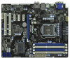
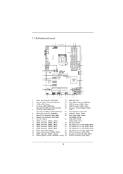
1.3 Motherboard Layout PS2 Keyboard USB 2.0 T: USB0 B: USB1 1 2 3 21.1cm (8.3 in) 4 5 PWR_FAN1 ATX12V1 DX10.1 DVI_CON1 VGA1 30.5cm (12.0 in) DDR3_A2 (64 bit, 240-pin module) DDR3_B1 (...: REAR SPK Bottom: Optical SPDIF Top: LINE IN Center: FRONT Bottom: MIC IN Designed in Taipei CHA_FAN1 CPU_FAN2 CPU_FAN1 34 CHA_FAN3 CHA_FAN2 33 LAN PHY H67DE3 7 8 32 PCIE1 PCI Express 2.0 CMOS ErP/EuP Ready 31 PCIE2 Battery USB 3.0 30 Super I/O PCIE3 Intel 9 H67 SATA3 6Gb/s 29 28 27 PCIE4 RoHS AUDIO...
1.3 Motherboard Layout PS2 Keyboard USB 2.0 T: USB0 B: USB1 1 2 3 21.1cm (8.3 in) 4 5 PWR_FAN1 ATX12V1 DX10.1 DVI_CON1 VGA1 30.5cm (12.0 in) DDR3_A2 (64 bit, 240-pin module) DDR3_B1 (...: REAR SPK Bottom: Optical SPDIF Top: LINE IN Center: FRONT Bottom: MIC IN Designed in Taipei CHA_FAN1 CPU_FAN2 CPU_FAN1 34 CHA_FAN3 CHA_FAN2 33 LAN PHY H67DE3 7 8 32 PCIE1 PCI Express 2.0 CMOS ErP/EuP Ready 31 PCIE2 Battery USB 3.0 30 Super I/O PCIE3 Intel 9 H67 SATA3 6Gb/s 29 28 27 PCIE4 RoHS AUDIO...
User Manual
Page 15
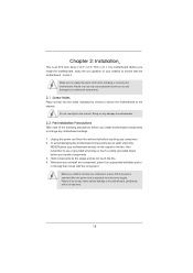
.... 3. Before you install or remove any component, ensure that comes with the component. Doing so may damage the motherboard. 2.2 Pre-installation Precautions Take note of your motherboard directly on a grounded antistatic pad or in the bag that the power is switched off or the power cord is... an ATX form factor (12.0" x 8.3", 30.5 x 21.1 cm) motherboard. To avoid damaging the motherboard components due to unplug the power cord before you and damages to motherboard components. 2.1 Screw Holes Place screws into it on the carpet or the like. Failure to the ...
.... 3. Before you install or remove any component, ensure that comes with the component. Doing so may damage the motherboard. 2.2 Pre-installation Precautions Take note of your motherboard directly on a grounded antistatic pad or in the bag that the power is switched off or the power cord is... an ATX form factor (12.0" x 8.3", 30.5 x 21.1 cm) motherboard. To avoid damaging the motherboard components due to unplug the power cord before you and damages to motherboard components. 2.1 Screw Holes Place screws into it on the carpet or the like. Failure to the ...
User Manual
Page 16
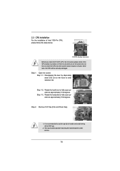
... the lever by depressing down and out on the socket. This cap must be seriously damaged. Otherwise, the CPU will be placed if returning the motherboard for after service. 16 Step 1-2. Remove PnP Cap (Pick and Place Cap). 1. Do not force to fully open position at approximately 100 degrees. Step 1. Step...
... the lever by depressing down and out on the socket. This cap must be seriously damaged. Otherwise, the CPU will be placed if returning the motherboard for after service. 16 Step 1-2. Remove PnP Cap (Pick and Place Cap). 1. Do not force to fully open position at approximately 100 degrees. Step 1. Step...
User Manual
Page 18
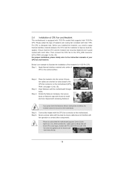
...heat. Step 1. Rotate the fastener clockwise, then press down the fasteners without rotating them clockwise, the heatsink cannot be noticed that this motherboard supports Combo Cooler Option (C.C.O.), which provides the exible option to adopt three different CPU cooler types, Socket LGA 775, LGA 1155 and... LGA 1156. Step 5. Step 6. The white throughholes are for 1155-Pin CPU. 2.4 Installation of CPU Fan and Heatsink This motherboard is an example to illustrate the installation of the heatsink for Socket LGA 1155/1156 CPU fan. 18 Before you installed the heatsink, ...
...heat. Step 1. Rotate the fastener clockwise, then press down the fasteners without rotating them clockwise, the heatsink cannot be noticed that this motherboard supports Combo Cooler Option (C.C.O.), which provides the exible option to adopt three different CPU cooler types, Socket LGA 775, LGA 1155 and... LGA 1156. Step 5. Step 6. The white throughholes are for 1155-Pin CPU. 2.4 Installation of CPU Fan and Heatsink This motherboard is an example to illustrate the installation of the heatsink for Socket LGA 1155/1156 CPU fan. 18 Before you installed the heatsink, ...
User Manual
Page 19
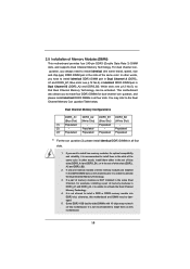
...) (Blue Slot) (White Slot) (1) Populated - It is unable to install them in Dual Channel A (DDR3_ A1 and DDR3_B1; otherwise, this motherboard. In other words, install them either in the set of white slots (DDR3_ A2 and DDR3_B2). 2. If a pair of memory modules is NOT ...activated. In other words, you to install four DDR3 DIMMs for optimal compatibility and reliability, it is unable to install them on this motherboard. 19 It is recommended to activate the Dual Channel Memory Technology . 4. guration, you want to install a DDR or DDR2 memory...
...) (Blue Slot) (White Slot) (1) Populated - It is unable to install them in Dual Channel A (DDR3_ A1 and DDR3_B1; otherwise, this motherboard. In other words, install them either in the set of white slots (DDR3_ A2 and DDR3_B2). 2. If a pair of memory modules is NOT ...activated. In other words, you to install four DDR3 DIMMs for optimal compatibility and reliability, it is unable to install them on this motherboard. 19 It is recommended to activate the Dual Channel Memory Technology . 4. guration, you want to install a DDR or DDR2 memory...
User Manual
Page 20
... 3. Step 1. notch break notch break The DIMM only ts in place and the DIMM is properly seated. 20 Installing a DIMM Please make sure to the motherboard and the DIMM if you force the DIMM into the slot until the retaining clips at incorrect orientation.
... 3. Step 1. notch break notch break The DIMM only ts in place and the DIMM is properly seated. 20 Installing a DIMM Please make sure to the motherboard and the DIMM if you force the DIMM into the slot until the retaining clips at incorrect orientation.
User Manual
Page 21
...connector with screws. PCI slots: PCI slots are 2 PCI slots and 4 PCI Express slots on the slot. Blue) is completely seated on this motherboard. Step 2. Step 5. 2.6 Expansion Slots (PCI and PCI Express Slots) There are used to install expansion cards that have the 32-bit PCI... interface. Remove the bracket facing the slot that you start the installation. Step 6. Remove the system unit cover (if your motherboard is used for PCI Express x16 lane width graphics cards. White) is already installed in a chassis). Installing an expansion card Step 1. ...
...connector with screws. PCI slots: PCI slots are 2 PCI slots and 4 PCI Express slots on the slot. Blue) is completely seated on this motherboard. Step 2. Step 5. 2.6 Expansion Slots (PCI and PCI Express Slots) There are used to install expansion cards that have the 32-bit PCI... interface. Remove the bracket facing the slot that you start the installation. Step 6. Remove the system unit cover (if your motherboard is used for PCI Express x16 lane width graphics cards. White) is already installed in a chassis). Installing an expansion card Step 1. ...
User Manual
Page 22
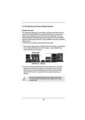
To enable dual monitor feature, please follow the below steps: 1. This motherboard also provides independent display controllers for DVI-D, D-Sub and HDMI to this motherboard. You can drive same or different display contents. VGA/D-Sub port VGA/DVI-D port HDMI port 2. With the internal VGA...: DVI-D + HDMI, DVI-D + D-Sub, or HDMI + D-Sub. 22 2.7 Dual Monitor and Surround Display Features Dual Monitor Feature This motherboard supports dual monitor feature. If you can easily enjoy the bene ts of dual monitor function after your computer. If you haven't installed onboard VGA...
To enable dual monitor feature, please follow the below steps: 1. This motherboard also provides independent display controllers for DVI-D, D-Sub and HDMI to this motherboard. You can drive same or different display contents. VGA/D-Sub port VGA/DVI-D port HDMI port 2. With the internal VGA...: DVI-D + HDMI, DVI-D + D-Sub, or HDMI + D-Sub. 22 2.7 Dual Monitor and Surround Display Features Dual Monitor Feature This motherboard supports dual monitor feature. If you can easily enjoy the bene ts of dual monitor function after your computer. If you haven't installed onboard VGA...
User Manual
Page 23
... use multiple monitors with your primary monitor, and then select "Primary". Click the "Identify" button to this monitor". D. Click "Extend my Windows desktop onto this motherboard. 4. Set the "Screen Resolution" and "Color Quality" as Secondary. Press or to apply these new values. A. Select the display icon identi ed by the number... driver to enable the function of "Onboard VGA Share Memory", [Auto], will be your card, one , two, three and four. 23 C. Surround Display Feature This motherboard supports surround display upgrade.
... use multiple monitors with your primary monitor, and then select "Primary". Click the "Identify" button to this monitor". D. Click "Extend my Windows desktop onto this motherboard. 4. Set the "Screen Resolution" and "Color Quality" as Secondary. Press or to apply these new values. A. Select the display icon identi ed by the number... driver to enable the function of "Onboard VGA Share Memory", [Auto], will be your card, one , two, three and four. 23 C. Surround Display Feature This motherboard supports surround display upgrade.
User Manual
Page 24
... set -top box and the digital display, or receiver - B. D. To use . Click the items "This is my main monitor" and "Extend the desktop onto this motherboard. Click "OK" to save your monitors that you can enjoy the superior display quality with high-de nition HDCP encryption contents. Therefore, you move items...-bit OS: Right click the desktop, choose "Personalize", and select the "Display Settings" tab so that you would like to use HDCP function with this motherboard, you purchase is compatible. 24
... set -top box and the digital display, or receiver - B. D. To use . Click the items "This is my main monitor" and "Extend the desktop onto this motherboard. Click "OK" to save your monitors that you can enjoy the superior display quality with high-de nition HDCP encryption contents. Therefore, you move items...-bit OS: Right click the desktop, choose "Personalize", and select the "Display Settings" tab so that you would like to use HDCP function with this motherboard, you purchase is compatible. 24
User Manual
Page 26
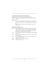
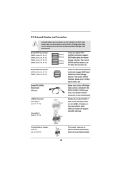
... rate. Each USB 2.0 header can be connected to the SATA / SATAII / SATA3 hard disk or the SATAII / SATA3 connector on this motherboard. Do NOT place jumper caps over the headers and connectors will cause permanent damage of the SATA data cable can support two USB 2.0 ports.... The current SATAII interface allows up to 3.0 Gb/s data transfer rate. 2.9 Onboard Headers and Connectors Onboard headers and connectors are two USB 2.0 headers on this motherboard. Serial ATAII Connectors (SATA2_2: see p.12, No. 11) (SATA2_3: see p.12, No. 12) (SATA2_4: see p.12, No. 13) (SATA2_5: see p.12...
... rate. Each USB 2.0 header can be connected to the SATA / SATAII / SATA3 hard disk or the SATAII / SATA3 connector on this motherboard. Do NOT place jumper caps over the headers and connectors will cause permanent damage of the SATA data cable can support two USB 2.0 ports.... The current SATAII interface allows up to 3.0 Gb/s data transfer rate. 2.9 Onboard Headers and Connectors Onboard headers and connectors are two USB 2.0 headers on this motherboard. Serial ATAII Connectors (SATA2_2: see p.12, No. 11) (SATA2_3: see p.12, No. 12) (SATA2_4: see p.12, No. 13) (SATA2_5: see p.12...
User Manual
Page 29
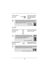
...FAN_SPEED_CONTROL 4 CPU_FAN_SPEED 3 +12V 2 GND 1 Please connect the CPU fan cable to the connector and match the black wire to the ground pin. Though this motherboard provides 4-Pin CPU fan (Quiet Fan) support, the 3-Pin CPU fan still can still work if you adopt a traditional 4-pin ATX 12V power supply.... Pin 1 and Pin 5. 8 5 4-Pin ATX 12V Power Supply Installation 4 1 29 If you adopt a traditional 20-pin ATX power supply. Though this motherboard provides 8-pin ATX 12V power connector, it can work if you plan to connect the 3-Pin CPU fan to the CPU fan connector on this...
...FAN_SPEED_CONTROL 4 CPU_FAN_SPEED 3 +12V 2 GND 1 Please connect the CPU fan cable to the connector and match the black wire to the ground pin. Though this motherboard provides 4-Pin CPU fan (Quiet Fan) support, the 3-Pin CPU fan still can still work if you adopt a traditional 4-pin ATX 12V power supply.... Pin 1 and Pin 5. 8 5 4-Pin ATX 12V Power Supply Installation 4 1 29 If you adopt a traditional 20-pin ATX power supply. Though this motherboard provides 8-pin ATX 12V power connector, it can work if you plan to connect the 3-Pin CPU fan to the CPU fan connector on this...
User Manual
Page 31
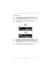
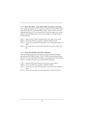
...install the SATA / SATAII hard disks. STEP 4: Connect the other end of your chassis. You may install SATA / SATAII hard disks on this motherboard for internal storage devices. STEP 3: Connect one end of your chassis. STEP 4: Connect the other end of the SATA data cable to the SATA3... hard disks into the drive bays of the SATA data cable to the SATA / SATAII hard disk. 2.11 Serial ATA3 (SATA3) Hard Disks Installation This motherboard adopts Intel® H67 chipset that supports Serial ATA (SATA) / Serial ATAII (SATAII) hard disks and RAID (RAID 0, RAID 1, RAID 10, RAID ...
...install the SATA / SATAII hard disks. STEP 4: Connect the other end of your chassis. You may install SATA / SATAII hard disks on this motherboard for internal storage devices. STEP 3: Connect one end of your chassis. STEP 4: Connect the other end of the SATA data cable to the SATA3... hard disks into the drive bays of the SATA data cable to the SATA / SATAII hard disk. 2.11 Serial ATA3 (SATA3) Hard Disks Installation This motherboard adopts Intel® H67 chipset that supports Serial ATA (SATA) / Serial ATAII (SATAII) hard disks and RAID (RAID 0, RAID 1, RAID 10, RAID ...

