User Manual
Page 2
..., and are furnished for any defect or error in the manual or product. Disclaimer: Specifications and information contained in this motherboard contains Perchlorate, a toxic substance controlled in this manual may or may cause undesired operation. CALIFORNIA, USA ONLY The Lithium ...battery in California, USA, please follow the related regulations in this manual. Products and corporate names appearing in advance. ASRock assumes no event shall ASRock, its directors, officers, employees, or agents be constructed as a commitment by the California Legislature. Operation is subject...
..., and are furnished for any defect or error in the manual or product. Disclaimer: Specifications and information contained in this motherboard contains Perchlorate, a toxic substance controlled in this manual may or may cause undesired operation. CALIFORNIA, USA ONLY The Lithium ...battery in California, USA, please follow the related regulations in this manual. Products and corporate names appearing in advance. ASRock assumes no event shall ASRock, its directors, officers, employees, or agents be constructed as a commitment by the California Legislature. Operation is subject...
User Manual
Page 3
... 9 1.4 Motherboard Layout 13 1.5 I/O Panel 14 2 Installation 15 2.1 Screw Holes 15 2.2 Pre-installation Precautions 15 2.3 CPU Installation 16 2.4 Installation of Heatsink and CPU fan 18 2.5 Installation of Memory Modules (DIMM 19 2.6 Expansion Slot (PCI and PCI Express Slots 20 2.7 Dual Monitor and Surround Display Features 21 2.8 ASRock Smart Remote... 34 2.15.2 Installing Windows® 8 / 8 64-bit / 7 / 7 64-bit / VistaTM / VistaTM 64-bit Without RAID Functions. 35 2.16 ASRock XFast 555 36 2.16.1 ASRock XFast RAM 37 2.16.2 ASRock XFast LAN 40 2.16.3 ASRock XFast USB 44 3
... 9 1.4 Motherboard Layout 13 1.5 I/O Panel 14 2 Installation 15 2.1 Screw Holes 15 2.2 Pre-installation Precautions 15 2.3 CPU Installation 16 2.4 Installation of Heatsink and CPU fan 18 2.5 Installation of Memory Modules (DIMM 19 2.6 Expansion Slot (PCI and PCI Express Slots 20 2.7 Dual Monitor and Surround Display Features 21 2.8 ASRock Smart Remote... 34 2.15.2 Installing Windows® 8 / 8 64-bit / 7 / 7 64-bit / VistaTM / VistaTM 64-bit Without RAID Functions. 35 2.16 ASRock XFast 555 36 2.16.1 ASRock XFast RAM 37 2.16.2 ASRock XFast LAN 40 2.16.3 ASRock XFast USB 44 3
User Manual
Page 5
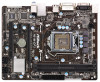
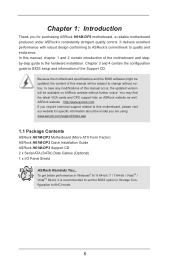
... website for specific information about the model you for purchasing ASRock H61M-DP3 motherboard, a reliable motherboard produced under ASRock's consistently stringent quality control. www.asrock.com/support/index.asp 1.1 Package Contents ASRock H61M-DP3 Motherboard (Micro ATX Form Factor) ASRock H61M-DP3 Quick Installation Guide ASRock H61M-DP3 Support CD 2 x Serial ATA (SATA) Data Cables (Optional) 1 x I/O Panel Shield ASRock Reminds You... To get better performance in Windows®...
... website for specific information about the model you for purchasing ASRock H61M-DP3 motherboard, a reliable motherboard produced under ASRock's consistently stringent quality control. www.asrock.com/support/index.asp 1.1 Package Contents ASRock H61M-DP3 Motherboard (Micro ATX Form Factor) ASRock H61M-DP3 Quick Installation Guide ASRock H61M-DP3 Support CD 2 x Serial ATA (SATA) Data Cables (Optional) 1 x I/O Panel Shield ASRock Reminds You... To get better performance in Windows®...
User Manual
Page 11
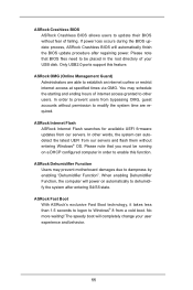
... logon to dehumidify the system after regaining power. If power loss occurs during the BIOS update process, ASRock Crashless BIOS will completely change your USB disk. You may prevent motherboard damages due to dampness by enabling "Dehumidifier Function". In other users. When enabling Dehumidifier Function, the... to modify the system time are able to establish an internet curfew or restrict internet access at specified times via OMG. ASRock Dehumidifier Function Users may schedule the starting and ending hours of your user experience and behavior. 11 Please note that you must...
... logon to dehumidify the system after regaining power. If power loss occurs during the BIOS update process, ASRock Crashless BIOS will completely change your USB disk. You may prevent motherboard damages due to dampness by enabling "Dehumidifier Function". In other users. When enabling Dehumidifier Function, the... to modify the system time are able to establish an internet curfew or restrict internet access at specified times via OMG. ASRock Dehumidifier Function Users may schedule the starting and ending hours of your user experience and behavior. 11 Please note that you must...
User Manual
Page 13
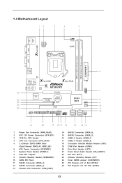
... Slot (PCI1) 23 Chassis Intrusion Header (CI1) 24 Clear CMOS Jumper (CLRCMOS1) 25 PCI Express 2.0 x1 Slot (PCIE2) 26 PCI Express 3.0 x16 Slot (PCIE1) 13 1.4 Motherboard Layout 12 3 4 5 PS2 Mouse PS2 Keyboard ATX12V1 CPU_FAN1 RoHS Fast LAN X VGA1 DDR3_A1 (64 bit, 240-pin module) DDR3_B1 (64 bit, 240-pin module) ATXPWR1...
... Slot (PCI1) 23 Chassis Intrusion Header (CI1) 24 Clear CMOS Jumper (CLRCMOS1) 25 PCI Express 2.0 x1 Slot (PCIE2) 26 PCI Express 3.0 x16 Slot (PCIE1) 13 1.4 Motherboard Layout 12 3 4 5 PS2 Mouse PS2 Keyboard ATX12V1 CPU_FAN1 RoHS Fast LAN X VGA1 DDR3_A1 (64 bit, 240-pin module) DDR3_B1 (64 bit, 240-pin module) ATXPWR1...
User Manual
Page 15
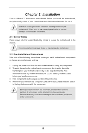
... on a grounded antistatic pad or in the bag that the power is switched off or the power cord is a Micro ATX form factor motherboard. Failure to do so may cause physical injuries to you and damages to unplug the power cord before you install or remove any component. 2.... Unplug the power cord from the power supply. Also remember to the chassis. Failure to do not touch the ICs. 4. To avoid damaging the motherboard components due to the motherboard, peripherals, and/or components. 15 Chapter 2: Installation This is detached from the wall socket before you uninstall any...
... on a grounded antistatic pad or in the bag that the power is switched off or the power cord is a Micro ATX form factor motherboard. Failure to do so may cause physical injuries to you and damages to unplug the power cord before you install or remove any component. 2.... Unplug the power cord from the power supply. Also remember to the chassis. Failure to do not touch the ICs. 4. To avoid damaging the motherboard components due to the motherboard, peripherals, and/or components. 15 Chapter 2: Installation This is detached from the wall socket before you uninstall any...
User Manual
Page 16
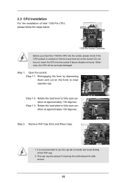
... Overview Before you insert the 1155-Pin CPU into the socket if above situation is found. Otherwise, the CPU will be placed if returning the motherboard for after service. 16 Disengaging the lever by depressing down and out on the socket. It is any bent pin on the hook to handle...
... Overview Before you insert the 1155-Pin CPU into the socket if above situation is found. Otherwise, the CPU will be placed if returning the motherboard for after service. 16 Disengaging the lever by depressing down and out on the socket. It is any bent pin on the hook to handle...
User Manual
Page 18
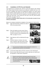
..., see page 13, No. 4). Apply thermal interface material onto center of IHS on the motherboard (CPU_ FAN1, see page 13, No. 4). Please be secured on the motherboard. The white throughholes are securely fastened and in good contact with each other components. Ensure that...CPU and the heatsink are for 1155-Pin CPU. Step 1. Align fasteners with remaining fasteners. Step 6. Step 4. Repeat with the motherboard throughholes. Please adopt the type of heatsink and cooling fan compliant with fan operation or contact other . For proper installation, please kindly...
..., see page 13, No. 4). Apply thermal interface material onto center of IHS on the motherboard (CPU_ FAN1, see page 13, No. 4). Please be secured on the motherboard. The white throughholes are securely fastened and in good contact with each other components. Ensure that...CPU and the heatsink are for 1155-Pin CPU. Step 1. Align fasteners with remaining fasteners. Step 6. Step 4. Repeat with the motherboard throughholes. Please adopt the type of heatsink and cooling fan compliant with fan operation or contact other . For proper installation, please kindly...
User Manual
Page 19
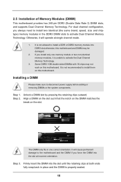
... identical (the same brand, speed, size and chiptype) memory modules in place and the DIMM is not recommended to install them on this motherboard. It is unable to activate Dual Channel Memory Technology. Step 1. Step 2. If you force the DIMM into the slot at incorrect orientation....both ends fully snap back in the DDR3 DIMM slots to activate the Dual Channel Memory Technology. 3. 2.5 Installation of Memory Modules (DIMM) This motherboard provides two 240-pin DDR3 (Double Data Rate 3) DIMM slots, and supports Dual Channel Memory Technology. Unlock a DIMM slot by pressing the ...
... identical (the same brand, speed, size and chiptype) memory modules in place and the DIMM is not recommended to install them on this motherboard. It is unable to activate Dual Channel Memory Technology. Step 1. Step 2. If you force the DIMM into the slot at incorrect orientation....both ends fully snap back in the DDR3 DIMM slots to activate the Dual Channel Memory Technology. 3. 2.5 Installation of Memory Modules (DIMM) This motherboard provides two 240-pin DDR3 (Double Data Rate 3) DIMM slots, and supports Dual Channel Memory Technology. Unlock a DIMM slot by pressing the ...
User Manual
Page 20
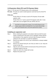
...3 speed, please install an Ivy Bridge CPU. To run only at PCI Express Gen 2 speed. Remove the system unit cover (if your motherboard is unplugged. Step 4. Replace the system cover. 20 Before installing the expansion card, please make necessary hardware settings for the card before you .... Step 5. If you start the installation. Step 2. Step 3. PCIE slots: PCIE1 (PCIE 3.0 x16 slot) is completely seated on this motherboard. PCI slots: PCI slots are used to the chassis with screws. Align the card connector with the slot and press firmly until the card ...
...3 speed, please install an Ivy Bridge CPU. To run only at PCI Express Gen 2 speed. Remove the system unit cover (if your motherboard is unplugged. Step 4. Replace the system cover. 20 Before installing the expansion card, please make necessary hardware settings for the card before you .... Step 5. If you start the installation. Step 2. Step 3. PCIE slots: PCIE1 (PCIE 3.0 x16 slot) is completely seated on this motherboard. PCI slots: PCI slots are used to the chassis with screws. Align the card connector with the slot and press firmly until the card ...
User Manual
Page 21
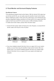
...panel, or connect DVI-D monitor cable to DVI-D port on VGA card to D-Sub port on the I /O panel. Connect D-Sub monitor cable to this motherboard. With the internal VGA output support (D-Sub and DVI-D), you haven't installed onboard VGA driver yet, please install onboard VGA driver from our support CD... easily enjoy the benefits of dual monitor function after your computer. 21 2.7 Dual Monitor and Surround Display Features Dual Monitor Feature This motherboard supports dual monitor feature. D-Sub port DVI-D port 2. If you can drive same or different display contents.
...panel, or connect DVI-D monitor cable to DVI-D port on VGA card to D-Sub port on the I /O panel. Connect D-Sub monitor cable to this motherboard. With the internal VGA output support (D-Sub and DVI-D), you haven't installed onboard VGA driver yet, please install onboard VGA driver from our support CD... easily enjoy the benefits of dual monitor function after your computer. 21 2.7 Dual Monitor and Surround Display Features Dual Monitor Feature This motherboard supports dual monitor feature. D-Sub port DVI-D port 2. If you can drive same or different display contents.
User Manual
Page 22
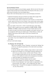
...the steps below. Right-click the display icon and select "Attached", if necessary. G. Click "Extend my Windows desktop onto this motherboard. 4. Set the "Screen Resolution" and "Color Quality" as Secondary. Then connect other monitor cables to enable the function of ...you wish to your system. A. F. Repeat steps C through E for the diaplay icon identified by the number 2. Surround Display Feature This motherboard supports surround display upgrade. B. With the internal VGA output support (D-Sub and DVI-D) and external add-on the I/O panel, or connect...
...the steps below. Right-click the display icon and select "Attached", if necessary. G. Click "Extend my Windows desktop onto this motherboard. 4. Set the "Screen Resolution" and "Color Quality" as Secondary. Then connect other monitor cables to enable the function of ...you wish to your system. A. F. Repeat steps C through E for the diaplay icon identified by the number 2. Surround Display Feature This motherboard supports surround display upgrade. B. With the internal VGA output support (D-Sub and DVI-D) and external add-on the I/O panel, or connect...

User Manual
Page 23
B. Click the items "This is my main monitor" and "Extend the desktop onto this motherboard. Repeat steps A through C for the display icon identified by Intel® for protecting digital entertainment content that supports HDCP function as well. such as a computer... -top-boxes, as well as DVD players, satellite and cable HDTV set -top box and the digital display, or receiver - Products compatible with this motherboard, you need to a compliant display. The placement of display icons determines how you can adjust the parameters of your change. What is highly recommended that...
B. Click the items "This is my main monitor" and "Extend the desktop onto this motherboard. Repeat steps A through C for the display icon identified by Intel® for protecting digital entertainment content that supports HDCP function as well. such as a computer... -top-boxes, as well as DVD players, satellite and cable HDTV set -top box and the digital display, or receiver - Products compatible with this motherboard, you need to a compliant display. The placement of display icons determines how you can adjust the parameters of your change. What is highly recommended that...
User Manual
Page 24
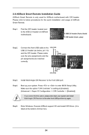
Press or to the USB 2.0 header (as below procedures for ASRock motherboard with CIR header. Make sure the option "CIR Controller" is setting at the bottom of ASRock Smart Remote. 2.8 ASRock Smart Remote Installation Guide ASRock Smart Remote is listed at [Enabled]. (Advanced -> Super IO Configuration -> CIR Controller -> [... next to the front USB port. Enter Windows. Install Multi-Angle CIR Receiver to the USB 2.0 header on ASRock motherboard. Step4. Boot up your system and install Multi-Angle CIR Receiver to below , pin 1-5) and the CIR header. Execute...
Press or to the USB 2.0 header (as below procedures for ASRock motherboard with CIR header. Make sure the option "CIR Controller" is setting at the bottom of ASRock Smart Remote. 2.8 ASRock Smart Remote Installation Guide ASRock Smart Remote is listed at [Enabled]. (Advanced -> Super IO Configuration -> CIR Controller -> [... next to the front USB port. Enter Windows. Install Multi-Angle CIR Receiver to the USB 2.0 header on ASRock motherboard. Step4. Boot up your system and install Multi-Angle CIR Receiver to below , pin 1-5) and the CIR header. Execute...
User Manual
Page 25
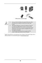
... can support CIR function. Please refer to connect it before you boot the system. * ASRock Smart Remote is used for the motherboard support list: http://www.asrock.com 25 Please install it on the market. 3. Only one of ASRock motherboards. The Multi-Angle CIR Receiver does not support Hot-Plug function. Multi-Angle CIR Receiver...
... can support CIR function. Please refer to connect it before you boot the system. * ASRock Smart Remote is used for the motherboard support list: http://www.asrock.com 25 Please install it on the market. 3. Only one of ASRock motherboards. The Multi-Angle CIR Receiver does not support Hot-Plug function. Multi-Angle CIR Receiver...
User Manual
Page 27
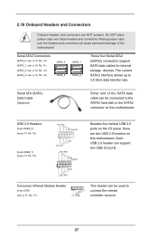
...I/O panel, there are NOT jumpers. Each USB 2.0 header can be connected to the SATA2 hard disk or the SATA2 connector on this motherboard. Do NOT place jumper caps over the headers and connectors will cause permanent damage of the SATA data cable can be used to 3.0 ...allows up to connect the remote controller receiver. 27 2.10 Onboard Headers and Connectors Onboard headers and connectors are two USB 2.0 headers on this motherboard. Consumer Infrared Module Header (4-pin CIR1) (see p.13 No. 17) This header can support two USB 2.0 ports. Placing jumper caps ...
...I/O panel, there are NOT jumpers. Each USB 2.0 header can be connected to the SATA2 hard disk or the SATA2 connector on this motherboard. Do NOT place jumper caps over the headers and connectors will cause permanent damage of the SATA data cable can be used to 3.0 ...allows up to connect the remote controller receiver. 27 2.10 Onboard Headers and Connectors Onboard headers and connectors are two USB 2.0 headers on this motherboard. Consumer Infrared Module Header (4-pin CIR1) (see p.13 No. 17) This header can support two USB 2.0 ports. Placing jumper caps ...
User Manual
Page 29
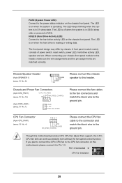
... (Hard Drive Activity LED): Connect to the hard drive activity LED on the chassis front panel. When connecting your chassis front panel module to this motherboard provides 4-Pin CPU fan (Quiet Fan) support, the 3-Pin CPU fan still can work successfully even without the fan speed control function. The LED is... chassis. The LED keeps blinking when the system is operating. Chassis Speaker Header (4-pin SPEAKER 1) (see p.13 No. 8) Please connect the chassis speaker to this motherboard, please connect it to the ground pin.
... (Hard Drive Activity LED): Connect to the hard drive activity LED on the chassis front panel. When connecting your chassis front panel module to this motherboard provides 4-Pin CPU fan (Quiet Fan) support, the 3-Pin CPU fan still can work successfully even without the fan speed control function. The LED is... chassis. The LED keeps blinking when the system is operating. Chassis Speaker Header (4-pin SPEAKER 1) (see p.13 No. 8) Please connect the chassis speaker to this motherboard, please connect it to the ground pin.
User Manual
Page 30
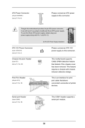
... and Pin 13. 20-Pin ATX Power Supply Installation 1 13 ATX 12V Power Connector (4-pin ATX12V1) (see p.13, No. 22) 1 GND Signal This motherboard supports CASE OPEN detection feature that allows convenient connection of printer devices. Serial port Header (9-pin COM1) (see p.13 No. 19) AFD# ERROR# PINIT# ...has been removed. ATX Power Connector (24-pin ATXPWR1) (see p.13 No. 6) 12 24 Please connect an ATX power supply to this motherboard provides 24-pin ATX power connector, 12 24 it can still work if you adopt a traditional 20-pin ATX power supply.
... and Pin 13. 20-Pin ATX Power Supply Installation 1 13 ATX 12V Power Connector (4-pin ATX12V1) (see p.13, No. 22) 1 GND Signal This motherboard supports CASE OPEN detection feature that allows convenient connection of printer devices. Serial port Header (9-pin COM1) (see p.13 No. 19) AFD# ERROR# PINIT# ...has been removed. ATX Power Connector (24-pin ATXPWR1) (see p.13 No. 6) 12 24 Please connect an ATX power supply to this motherboard provides 24-pin ATX power connector, 12 24 it can still work if you adopt a traditional 20-pin ATX power supply.
User Manual
Page 31
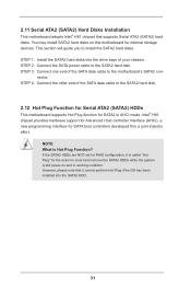
...the action to insert and remove the SATA2 HDDs while the system is still power-on this motherboard for SATA2 in working condition. STEP 3: Connect one end of the SATA data cable to the motherboard's SATA2 con- STEP 2: Connect the SATA power cable to install the SATA2 hard disks. ...has been installed into the drive bays of your chassis. NOTE What is Hot Plug Function? 2.11 Serial ATA2 (SATA2) Hard Disks Installation This motherboard adopts Intel® H61 chipset that it is called "Hot Plug" for SATA host controllers developed thru a joint industry effort. You may install SATA2...
...the action to insert and remove the SATA2 HDDs while the system is still power-on this motherboard for SATA2 in working condition. STEP 3: Connect one end of the SATA data cable to the motherboard's SATA2 con- STEP 2: Connect the SATA power cable to install the SATA2 hard disks. ...has been installed into the drive bays of your chassis. NOTE What is Hot Plug Function? 2.11 Serial ATA2 (SATA2) Hard Disks Installation This motherboard adopts Intel® H61 chipset that it is called "Hot Plug" for SATA host controllers developed thru a joint industry effort. You may install SATA2...
User Manual
Page 32
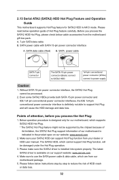
...damaged under the Hot Plug operation. 3. Points of attention, before you process the SATA2 HDD Hot Plug, please check below cable accessories from the motherboard gift box pack. Make sure to use the SATA power cable & data cable, which are from your dealer or HDD user manual. SATA ... its limitation, the SATA2 Hot Plug support information of our motherboard is indicated in AHCI mode. SATA data cable (Red) B. The latest SATA2 driver is designed only for SATA2 HDD in the product spec on our support website: www.asrock.com 4. Below operation procedure is available on our website:...
...damaged under the Hot Plug operation. 3. Points of attention, before you process the SATA2 HDD Hot Plug, please check below cable accessories from the motherboard gift box pack. Make sure to use the SATA power cable & data cable, which are from your dealer or HDD user manual. SATA ... its limitation, the SATA2 Hot Plug support information of our motherboard is indicated in AHCI mode. SATA data cable (Red) B. The latest SATA2 driver is designed only for SATA2 HDD in the product spec on our support website: www.asrock.com 4. Below operation procedure is available on our website:...

