User Manual
Page 3
... CrossFireXTM Graphics Card Support List 11 1.4 Motherboard Layout 12 1.5 I/O Panel 13 2 Installation 15 2.1 Screw Holes 15 2.2 Pre-installation Precautions 15 2.3 CPU Installation 16 2.4 Installation of Heatsink and CPU fan 18 2.5 Installation of Memory Modules (DIMM 19 2.6 Expansion Slots (PCI and PCI Express Slots 21 2.7 CrossFireXTM and Quad CrossFireXTM Operation Guide 22 2.8 Surround Display Feature 26 2.9 Jumpers Setup 26 2.10 Onboard Headers and Connectors 27 2.11 HDMI_SPDIF Header Connection Guide 32 2.12 SATAII Hard Disk Setup Guide 33 2.13 Serial ATA (SATA) / Serial...
... CrossFireXTM Graphics Card Support List 11 1.4 Motherboard Layout 12 1.5 I/O Panel 13 2 Installation 15 2.1 Screw Holes 15 2.2 Pre-installation Precautions 15 2.3 CPU Installation 16 2.4 Installation of Heatsink and CPU fan 18 2.5 Installation of Memory Modules (DIMM 19 2.6 Expansion Slots (PCI and PCI Express Slots 21 2.7 CrossFireXTM and Quad CrossFireXTM Operation Guide 22 2.8 Surround Display Feature 26 2.9 Jumpers Setup 26 2.10 Onboard Headers and Connectors 27 2.11 HDMI_SPDIF Header Connection Guide 32 2.12 SATAII Hard Disk Setup Guide 33 2.13 Serial ATA (SATA) / Serial...
User Manual
Page 9
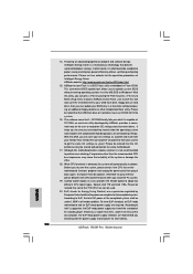
..., this motherboard supports 2-channel, 4-channel, 6-channel, and 8-channel modes. Please visit our website for details. 4. For Windows® OS with the DVIto-HDMI adapter, the DVI-D port can also connect SATA hard disk to SATAII connector, please read the "SATAII Hard Disk Setup Guide" on page 13 for system usage under Windows® 7 64-bit / 7 / VistaTM 64-bit / VistaTM. 10. For those CPU that delivers unparalleled power savings. This motherboard supports Untied Overclocking Technology. Besides, with 64-bit CPU, there...
..., this motherboard supports 2-channel, 4-channel, 6-channel, and 8-channel modes. Please visit our website for details. 4. For Windows® OS with the DVIto-HDMI adapter, the DVI-D port can also connect SATA hard disk to SATAII connector, please read the "SATAII Hard Disk Setup Guide" on page 13 for system usage under Windows® 7 64-bit / 7 / VistaTM 64-bit / VistaTM. 10. For those CPU that delivers unparalleled power savings. This motherboard supports Untied Overclocking Technology. Besides, with 64-bit CPU, there...
User Manual
Page 10
... if the CPU fan on the same motherboard. 17. Although this utility, you to access ASRock Instant Flash. While CPU overheat is not recommended to Intel's suggestion, the EuP ready power supply must use FAT32/16/12 file system. 16. Please be noticed that the OC profile can press key during the POST or press key to BIOS setup menu to update system BIOS without preparing an additional floppy diskette or...
... if the CPU fan on the same motherboard. 17. Although this utility, you to access ASRock Instant Flash. While CPU overheat is not recommended to Intel's suggestion, the EuP ready power supply must use FAT32/16/12 file system. 16. Please be noticed that the OC profile can press key during the POST or press key to BIOS setup menu to update system BIOS without preparing an additional floppy diskette or...
User Manual
Page 12
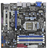
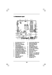
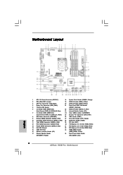
...USB 2.0 Header (USB6_7, Blue) 3 CPU Fan Connector (CPU_FAN1) 20 USB 2.0 Header (USB8_9, Blue) 4 Power Fan Connector (PWR_FAN1) 21 Front Panel IEEE 1394 Header 5 1156-Pin CPU Socket (FRONT_1394, Red) 6 2 x 240-pin DDR3 DIMM Slots 22 USB 2.0 Header (USB10_11, Blue) (Dual Channel: DDR3_A2, DDR3_B2, Blue) 23 Infrared Module Header (IR1) 7 2 x 240-pin DDR3 DIMM Slots 24 Clear CMOS Jumper (CLRCMOS1) (Dual Channel: DDR3_A1, DDR3_B1, White) 25 Chassis Fan Connector (CHA_FAN1) 8 ATX Power Connector (ATXPWR1) 26 TPM Header (TPM1) 9 Primary SATAII Connector (SATAII_1, Red) 27 Print Port...
...USB 2.0 Header (USB6_7, Blue) 3 CPU Fan Connector (CPU_FAN1) 20 USB 2.0 Header (USB8_9, Blue) 4 Power Fan Connector (PWR_FAN1) 21 Front Panel IEEE 1394 Header 5 1156-Pin CPU Socket (FRONT_1394, Red) 6 2 x 240-pin DDR3 DIMM Slots 22 USB 2.0 Header (USB10_11, Blue) (Dual Channel: DDR3_A2, DDR3_B2, Blue) 23 Infrared Module Header (IR1) 7 2 x 240-pin DDR3 DIMM Slots 24 Clear CMOS Jumper (CLRCMOS1) (Dual Channel: DDR3_A1, DDR3_B1, White) 25 Chassis Fan Connector (CHA_FAN1) 8 ATX Power Connector (ATXPWR1) 26 TPM Header (TPM1) 9 Primary SATAII Connector (SATAII_1, Red) 27 Print Port...

User Manual
Page 24
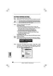
... is an optional download. Click "Apply". 24 The Catalyst Uninstaller is no need to be installed (If you have Windows® XP Service Pack 2 or higher installed in your system. Step 5. For Windows® XP OS: A. Please check Microsoft website for ATITM driver updates. Install the VGA card drivers to your Windows® taskbar. Double-click "ATI Catalyst Control Center". Please check AMD website for details...
... is an optional download. Click "Apply". 24 The Catalyst Uninstaller is no need to be installed (If you have Windows® XP Service Pack 2 or higher installed in your system. Step 5. For Windows® XP OS: A. Please check Microsoft website for ATITM driver updates. Install the VGA card drivers to your Windows® taskbar. Double-click "ATI Catalyst Control Center". Please check AMD website for details...

User Manual
Page 29
... chassis speaker to Ground (GND). Connect Ground (GND) to this header. MIC_RET and OUT_RET are for AC'97 audio panel. Enter Advanced Settings, and then select Chipset Configuration. Set the Front Panel Control option from [Auto] to this connector and match the black wire to Pin 1-3. Pin 1-3 Connected 3-Pin Fan Installation ATX Power Connector (24-pin ATXPWR1) (see p.12, No. 8) 12 24 Please connect an ATX power supply to [Enabled]. Enter BIOS Setup Utility. Please connect the fan cables to the fan connectors and match the black wire to connect them for HD audio...
... chassis speaker to Ground (GND). Connect Ground (GND) to this header. MIC_RET and OUT_RET are for AC'97 audio panel. Enter Advanced Settings, and then select Chipset Configuration. Set the Front Panel Control option from [Auto] to this connector and match the black wire to Pin 1-3. Pin 1-3 Connected 3-Pin Fan Installation ATX Power Connector (24-pin ATXPWR1) (see p.12, No. 8) 12 24 Please connect an ATX power supply to [Enabled]. Enter BIOS Setup Utility. Please connect the fan cables to the fan connectors and match the black wire to connect them for HD audio...
User Manual
Page 32
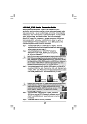
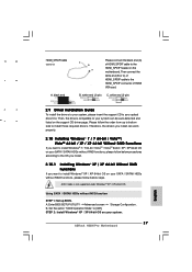
... HDMI VGA card to your system. 32 Install HDMI VGA card driver to the• PCI Express Graphics slot on HDMI VGA card to the VGA card user manual for detailed connection procedures. Step 3. For example, this motherboard, please carefully follow the below steps. Please refer to the fan connector of HDTV and HDMI VGA card vendor for connector usage in advance. For the proper installation of HDMI_SPDIF header and HDMI_SPDIF cable connectors, please refer to the installation guide on HDMI_SPDIF cable. 2.11 HDMI_SPDIF Header Connection Guide HDMI (High...
... HDMI VGA card to your system. 32 Install HDMI VGA card driver to the• PCI Express Graphics slot on HDMI VGA card to the VGA card user manual for detailed connection procedures. Step 3. For example, this motherboard, please carefully follow the below steps. Please refer to the fan connector of HDTV and HDMI VGA card vendor for connector usage in advance. For the proper installation of HDMI_SPDIF header and HDMI_SPDIF cable connectors, please refer to the installation guide on HDMI_SPDIF cable. 2.11 HDMI_SPDIF Header Connection Guide HDMI (High...
User Manual
Page 37
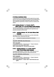
... support CD driver page. Using SATA / SATAII HDDs with NCQ function STEP 1: Set Up BIOS. Set the option "SATA Operation Mode" to [IDE]. Therefore, the drivers you install can be auto-detected and listed on your SATA / SATAII HDDs without RAID functions, please follow below steps. Enter BIOS SETUP UTILITY Advanced screen Storage Configuration. Enter BIOS SETUP UTILITY Advanced screen Storage Configuration. A. Set the option "SATA Operation Mode" to [AHCI]. B. B. STEP 2: Install Windows® 7 / 7 64-bit / VistaTM / VistaTM 64-bit OS on your optical drive first...
... support CD driver page. Using SATA / SATAII HDDs with NCQ function STEP 1: Set Up BIOS. Set the option "SATA Operation Mode" to [IDE]. Therefore, the drivers you install can be auto-detected and listed on your SATA / SATAII HDDs without RAID functions, please follow below steps. Enter BIOS SETUP UTILITY Advanced screen Storage Configuration. Enter BIOS SETUP UTILITY Advanced screen Storage Configuration. A. Set the option "SATA Operation Mode" to [AHCI]. B. B. STEP 2: Install Windows® 7 / 7 64-bit / VistaTM / VistaTM 64-bit OS on your optical drive first...

User Manual
Page 41
... It should be turned off Power LED and Lan LED when the system is enabled. It should be done at your CPU and motherboard. Configuration options: [Auto], [Manual], [I.O.T.] and [Optimized]. BIOS SETUP UTILITY Main OC Tweaker Advanced H/W Monitor Boot Security Exit OC Tweaker Settings Load CPU EZ OC Setting [Press Enter] Load Memory EZ OC Setting [Press Enter] Load XMP Setting [Disabled] Profile 1 : DDR3 2000 9-9-9-27 1.65V Intelligent Energy Saver Good Night LED [Disabled] Overclock Mode BCLK Frequency (MHz) PCIE Frequency (MHz) Boot Failure Guard Spread Spectrum...
... It should be turned off Power LED and Lan LED when the system is enabled. It should be done at your CPU and motherboard. Configuration options: [Auto], [Manual], [I.O.T.] and [Optimized]. BIOS SETUP UTILITY Main OC Tweaker Advanced H/W Monitor Boot Security Exit OC Tweaker Settings Load CPU EZ OC Setting [Press Enter] Load Memory EZ OC Setting [Press Enter] Load XMP Setting [Disabled] Profile 1 : DDR3 2000 9-9-9-27 1.65V Intelligent Energy Saver Good Night LED [Disabled] Overclock Mode BCLK Frequency (MHz) PCIE Frequency (MHz) Boot Failure Guard Spread Spectrum...

User Manual
Page 48
... Video Memory Technology) is [PCI]. The default value is cooperatively using this option to select [Onboard], [PCI] or [PCI Express] as needed for the motherboard through efficient memory utilization. In DVMT mode, the graphics driver allocates memory as the boot graphic adapter priority. Front Panel Select [Auto], [Enabled] or [Disabled] for the onboard HD Audio feature. 3.4.2Chipset Configuration BIOS SETUP UTILITY Advanced Chipset Settings Primary Graphics Adapter Share Memory DVMT Mode Select DVMT/FIXED Memory Onboard HD Audio Front Panel Onboard HDMI HD Audio OnBoard...
... Video Memory Technology) is [PCI]. The default value is cooperatively using this option to select [Onboard], [PCI] or [PCI Express] as needed for the motherboard through efficient memory utilization. In DVMT mode, the graphics driver allocates memory as the boot graphic adapter priority. Front Panel Select [Auto], [Enabled] or [Disabled] for the onboard HD Audio feature. 3.4.2Chipset Configuration BIOS SETUP UTILITY Advanced Chipset Settings Primary Graphics Adapter Share Memory DVMT Mode Select DVMT/FIXED Memory Onboard HD Audio Front Panel Onboard HDMI HD Audio OnBoard...

User Manual
Page 53
Configuration options: [Disabled], [Auto], [Enabled]. 32-Bit Data Transfer Use this item to enable 32-bit access to enable or disable the PCI IDE BusMaster feature. 53 Use this item to maximize the IDE hard disk data transfer rate. 3.4.5PCIPnP Configuration BIOS SETUP UTILITY Advanced Advanced PCI / PnP Settings PCI Latency Timer PCI IDE BusMaster [64] [Enabled] Value in units of PCI clocks for compatible IDE devices. PCI Latency Timer The default value is recommended to enable or disable the S.M.A.R.T. (Self-Monitoring, Analysis, and Reporting Technology) feature. DMA Mode DMA...
Configuration options: [Disabled], [Auto], [Enabled]. 32-Bit Data Transfer Use this item to enable 32-bit access to enable or disable the PCI IDE BusMaster feature. 53 Use this item to maximize the IDE hard disk data transfer rate. 3.4.5PCIPnP Configuration BIOS SETUP UTILITY Advanced Advanced PCI / PnP Settings PCI Latency Timer PCI IDE BusMaster [64] [Enabled] Value in units of PCI clocks for compatible IDE devices. PCI Latency Timer The default value is recommended to enable or disable the S.M.A.R.T. (Self-Monitoring, Analysis, and Reporting Technology) feature. DMA Mode DMA...

User Manual
Page 55
... options: [Enabled] - USB devices are allowed to enable or disable the use under BIOS setup and Windows / Linux OS. If you have USB compatibility issue, it is [Enabled]. Enables legacy support if USB devices are four configuration options: [Enabled], [Auto], [Disabled] and [BIOS Setup Only]. 3.4.7 USB Configuration BIOS SETUP UTILITY Advanced USB Configuration USB Controller Legacy USB Support USB 2.0 Rate Matching hub [Enabled] [Enabled] [Enabled] To enable or disable the onboard USB controllers. +F1 F9 F10 ESC Select Screen Select Item Change Option General Help Load Defaults...
... options: [Enabled] - USB devices are allowed to enable or disable the use under BIOS setup and Windows / Linux OS. If you have USB compatibility issue, it is [Enabled]. Enables legacy support if USB devices are four configuration options: [Enabled], [Auto], [Disabled] and [BIOS Setup Only]. 3.4.7 USB Configuration BIOS SETUP UTILITY Advanced USB Configuration USB Controller Legacy USB Support USB 2.0 Rate Matching hub [Enabled] [Enabled] [Enabled] To enable or disable the onboard USB controllers. +F1 F9 F10 ESC Select Screen Select Item Change Option General Help Load Defaults...

User Manual
Page 58
.../user password for the system. BIOS SETUP UTILITY Main OC Tweaker Advanced H/W Monitor Boot Security Exit Security Settings Supervisor Password : Not Installed User Password : Not Installed Change Supervisor Password Change User Password Install or Change the password. Boot Up Num-Lock If this section, you may also clear it will automatically activate the Numeric Lock function after boot-up. 3.7 Security Screen In this item is [Auto]. Boot Logo Use this item to enable or disable the Boot From Onboard LAN feature. Configuration options: [Auto], [EuP], [Scenery] and [ASRock...
.../user password for the system. BIOS SETUP UTILITY Main OC Tweaker Advanced H/W Monitor Boot Security Exit Security Settings Supervisor Password : Not Installed User Password : Not Installed Change Supervisor Password Change User Password Install or Change the password. Boot Up Num-Lock If this section, you may also clear it will automatically activate the Numeric Lock function after boot-up. 3.7 Security Screen In this item is [Auto]. Boot Logo Use this item to enable or disable the Boot From Onboard LAN feature. Configuration options: [Auto], [EuP], [Scenery] and [ASRock...
User Manual
Page 60
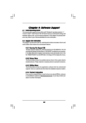
... general reference only. Please install the necessary drivers to your CD-ROM drive. or you need to contact ASRock or want to display the menus. 4.2.2 Drivers Menu The Drivers Menu shows the available devices drivers if the system detects installed devices. Chapter 4: Software Support 4.1 Install Operating System This motherboard supports various Microsoft® Windows® operating systems: 7 / 7 64-bit / VistaTM / VistaTM 64-bit / XP / XP 64-bit. Click on the file "ASSETUP.EXE" from...
... general reference only. Please install the necessary drivers to your CD-ROM drive. or you need to contact ASRock or want to display the menus. 4.2.2 Drivers Menu The Drivers Menu shows the available devices drivers if the system detects installed devices. Chapter 4: Software Support 4.1 Install Operating System This motherboard supports various Microsoft® Windows® operating systems: 7 / 7 64-bit / VistaTM / VistaTM 64-bit / XP / XP 64-bit. Click on the file "ASSETUP.EXE" from...
Quick Installation Guide
Page 2
Motherboard Layout English 1 ATX 12V Power Connector (ATX12V1) 18 System Panel Header (PANEL1, Orange) 2 PS2_USB_PWR1 Jumper 19 USB 2.0 Header (USB6_7, Blue) 3 CPU Fan Connector (CPU_FAN1) 20 USB 2.0 Header (USB8_9, Blue) 4 Power Fan Connector (PWR_FAN1) 21 Front Panel IEEE 1394 Header 5 1156-Pin CPU Socket (FRONT_1394, Red) 6 2 x 240-pin DDR3 DIMM Slots 22 USB 2.0 Header (USB10_11, Blue) (Dual Channel: DDR3_A2, DDR3_B2, Blue) 23 Infrared Module Header (IR1) 7 2 x 240-pin DDR3 DIMM Slots 24 Clear CMOS Jumper (CLRCMOS1) (Dual Channel: DDR3_A1, DDR3_B1, White) 25 Chassis Fan ...
Motherboard Layout English 1 ATX 12V Power Connector (ATX12V1) 18 System Panel Header (PANEL1, Orange) 2 PS2_USB_PWR1 Jumper 19 USB 2.0 Header (USB6_7, Blue) 3 CPU Fan Connector (CPU_FAN1) 20 USB 2.0 Header (USB8_9, Blue) 4 Power Fan Connector (PWR_FAN1) 21 Front Panel IEEE 1394 Header 5 1156-Pin CPU Socket (FRONT_1394, Red) 6 2 x 240-pin DDR3 DIMM Slots 22 USB 2.0 Header (USB10_11, Blue) (Dual Channel: DDR3_A2, DDR3_B2, Blue) 23 Infrared Module Header (IR1) 7 2 x 240-pin DDR3 DIMM Slots 24 Clear CMOS Jumper (CLRCMOS1) (Dual Channel: DDR3_A1, DDR3_B1, White) 25 Chassis Fan ...

Quick Installation Guide
Page 9
... SP1 or SP2. 13. Please read the installation guide of "User Manual" in the support CD to adjust your hardware devices to SATAII mode. Please check Intel® website for USB 2.0 works fine under Windows® 7 64-bit / 7. You can choose to SATAII connector directly. 12. ASRock website: http://www.asrock.com/feature/OCTuner/index.htm 9 ASRock H55M Pro Motherboard English Power Management for the latest information. 8. Please check...
... SP1 or SP2. 13. Please read the installation guide of "User Manual" in the support CD to adjust your hardware devices to SATAII mode. Please check Intel® website for USB 2.0 works fine under Windows® 7 64-bit / 7. You can choose to SATAII connector directly. 12. ASRock website: http://www.asrock.com/feature/OCTuner/index.htm 9 ASRock H55M Pro Motherboard English Power Management for the latest information. 8. Please check...
Quick Installation Guide
Page 10
... OC profile can save the new BIOS file to your USB flash drive, floppy disk or hard drive, then you checking with your overclocking record under 100 mA current consumption. This convenient BIOS update tool allows you can only be used. 20. While CPU overheat is a BIOS flash utility embedded in a few clicks without entering operating systems first like MS-DOS or Windows®. Frequencies other than 50% under the...
... OC profile can save the new BIOS file to your USB flash drive, floppy disk or hard drive, then you checking with your overclocking record under 100 mA current consumption. This convenient BIOS update tool allows you can only be used. 20. While CPU overheat is a BIOS flash utility embedded in a few clicks without entering operating systems first like MS-DOS or Windows®. Frequencies other than 50% under the...
Quick Installation Guide
Page 20
... computer and boot into OS. Please check Microsoft website for ATITM driver updates. Then you have Microsoft .NET Framework installed prior to the total GPU number on the Radeon graphics cards. Select the option according to downloading and installing the CATALYST Control Center. Click "Apply". English 20 ASRock H55M Pro Motherboard Please check AMD website for details. Step 5. You must have Windows® XP Service Pack 2 or...
... computer and boot into OS. Please check Microsoft website for ATITM driver updates. Then you have Microsoft .NET Framework installed prior to the total GPU number on the Radeon graphics cards. Select the option according to downloading and installing the CATALYST Control Center. Click "Apply". English 20 ASRock H55M Pro Motherboard Please check AMD website for details. Step 5. You must have Windows® XP Service Pack 2 or...
Quick Installation Guide
Page 27
... the HDMI_SPDIF header on 1 6 HDMI_SPDIF Cable (Optional) A. Set the option "SATA Operation Mode" to your system. 27 ASRock H55M Pro Motherboard English Then connect the white end (B or C) of HDMI_SPDIF cable to the HDMI_SPDIF connector of HDMI_SPDIF cable to install Windows® 7 / 7 64-bit / VistaTM / VistaTM 64-bit / XP / XP 64-bit OS on your SATA / SATAII HDDs without RAID functions, please follow below procedures according to install those required drivers. A. white end (2-pin) C. black end...
... the HDMI_SPDIF header on 1 6 HDMI_SPDIF Cable (Optional) A. Set the option "SATA Operation Mode" to your system. 27 ASRock H55M Pro Motherboard English Then connect the white end (B or C) of HDMI_SPDIF cable to the HDMI_SPDIF connector of HDMI_SPDIF cable to install Windows® 7 / 7 64-bit / VistaTM / VistaTM 64-bit / XP / XP 64-bit OS on your SATA / SATAII HDDs without RAID functions, please follow below procedures according to install those required drivers. A. white end (2-pin) C. black end...
Quick Installation Guide
Page 29
... Flash Memory on the file "ASSETUP.EXE" from the BIN folder in the Support CD to display the menus. 29 ASRock H55M Pro Motherboard English For the detailed information about BIOS Setup, please refer to enter BIOS Setup utility; The Support CD that will display the Main Menu automatically if "AUTORUN" is enabled in the Support CD. 4. If you start up the computer, please press during the Power-On-Self-Test (POST) to the User Manual (PDF file...
... Flash Memory on the file "ASSETUP.EXE" from the BIN folder in the Support CD to display the menus. 29 ASRock H55M Pro Motherboard English For the detailed information about BIOS Setup, please refer to enter BIOS Setup utility; The Support CD that will display the Main Menu automatically if "AUTORUN" is enabled in the Support CD. 4. If you start up the computer, please press during the Power-On-Self-Test (POST) to the User Manual (PDF file...


