

User Manual
Page 2
...means, except duplication of any errors or omissions that may cause undesired operation. Version 1.0 Published June 2015 Copyright©2015 ASRock INC. Disclaimer: Specifications and information contained in the documentation or product. In no responsibility for informational use only and subject to... are used only for identification or explanation and to the owners' benefit, without written consent of ASRock Inc. "Perchlorate Material-special handling may not be liable for any defect or error in this motherboard contains Perchlorate, a toxic substance controlled in advance.
...means, except duplication of any errors or omissions that may cause undesired operation. Version 1.0 Published June 2015 Copyright©2015 ASRock INC. Disclaimer: Specifications and information contained in the documentation or product. In no responsibility for informational use only and subject to... are used only for identification or explanation and to the owners' benefit, without written consent of ASRock Inc. "Perchlorate Material-special handling may not be liable for any defect or error in this motherboard contains Perchlorate, a toxic substance controlled in advance.

User Manual
Page 4
Contents Chapter 1 Introduction 1 1.1 Package Contents 1 1.2 Specifications 2 1.3 Motherboard Layout 6 1.4 I/O Panel 8 Chapter 2 Installation 10 2.1 Installing the CPU 11 2.2 Installing the CPU Fan and Heatsink 14 2.3 Installing Memory Modules (DIMM) 15 2.4 Expansion Slots (PCI Express ... Graphics Cards 24 2.7.2 Driver Installation and Setup 26 2.8 M.2_SSD (NGFF) Module Installation Guide 27 Chapter 3 Software and Utilities Operation 30 3.1 Installing Drivers 30 3.2 A-Tuning 31 3.3 ASRock Live Update & APP Shop 35 3.3.1 UI Overview 35 3.3.2 Apps 36
Contents Chapter 1 Introduction 1 1.1 Package Contents 1 1.2 Specifications 2 1.3 Motherboard Layout 6 1.4 I/O Panel 8 Chapter 2 Installation 10 2.1 Installing the CPU 11 2.2 Installing the CPU Fan and Heatsink 14 2.3 Installing Memory Modules (DIMM) 15 2.4 Expansion Slots (PCI Express ... Graphics Cards 24 2.7.2 Driver Installation and Setup 26 2.8 M.2_SSD (NGFF) Module Installation Guide 27 Chapter 3 Software and Utilities Operation 30 3.1 Installing Drivers 30 3.2 A-Tuning 31 3.3 ASRock Live Update & APP Shop 35 3.3.1 UI Overview 35 3.3.2 Apps 36
User Manual
Page 6
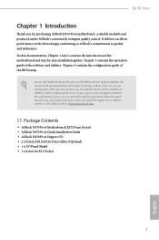
... and CPU support list on ASRock's website without notice. ASRock website http://www.asrock.com. 1.1 Package Contents • ASRock H170 Pro4 Motherboard (ATX Form Factor) • ASRock H170 Pro4 Quick Installation Guide • ASRock H170 Pro4 Support CD • 2 x Serial ATA (SATA) Data Cables (Optional) • 1 x I/O Panel Shield • 1 x Screw for purchasing ASRock H170 Pro4 motherboard, a reliable motherboard produced under ASRock's consistently stringent quality control. H170 Pro4 Chapter 1 Introduction Thank you...
... and CPU support list on ASRock's website without notice. ASRock website http://www.asrock.com. 1.1 Package Contents • ASRock H170 Pro4 Motherboard (ATX Form Factor) • ASRock H170 Pro4 Quick Installation Guide • ASRock H170 Pro4 Support CD • 2 x Serial ATA (SATA) Data Cables (Optional) • 1 x I/O Panel Shield • 1 x Screw for purchasing ASRock H170 Pro4 motherboard, a reliable motherboard produced under ASRock's consistently stringent quality control. H170 Pro4 Chapter 1 Introduction Thank you...

User Manual
Page 11
1.3 Motherboard Layout ATX12V1 PS2 Keyboard /Mouse USB 3.0 T: USB1 B: USB2 HDMI1 DDR4_A1 (64 bit, 288-pin module) DDR4_A2 (64 bit, 288-pin module) DDR4_B1 (64 bit, 288-... Bottom: CTR BASS Top: LINE IN Center: FRONT Bottom: MIC IN USB 3.0 T: USB3 B: USB4 USB 3.0 T: USB5 B: USB6 Top: RJ-45 PCIE_PWR1 CPU_FAN1 USB3_7_8 CHA_FAN3 PCIE1 H170 Pro4 PCIE2 PCI Express 3.0 Ultra M.2 PCIe Gen3 x4 CT5 CT4 CT3 CT2 CT1 M2_1 1 Front USB 3.0 HD_AUDIO1 1 PCIE3 PCIE4 RoHS CLRMOS1 1 Intel...
1.3 Motherboard Layout ATX12V1 PS2 Keyboard /Mouse USB 3.0 T: USB1 B: USB2 HDMI1 DDR4_A1 (64 bit, 288-pin module) DDR4_A2 (64 bit, 288-pin module) DDR4_B1 (64 bit, 288-... Bottom: CTR BASS Top: LINE IN Center: FRONT Bottom: MIC IN USB 3.0 T: USB3 B: USB4 USB 3.0 T: USB5 B: USB6 Top: RJ-45 PCIE_PWR1 CPU_FAN1 USB3_7_8 CHA_FAN3 PCIE1 H170 Pro4 PCIE2 PCI Express 3.0 Ultra M.2 PCIe Gen3 x4 CT5 CT4 CT3 CT2 CT1 M2_1 1 Front USB 3.0 HD_AUDIO1 1 PCIE3 PCIE4 RoHS CLRMOS1 1 Intel...

User Manual
Page 15
..., NEVER place your chassis to ensure that comes with the components. • When placing screws to secure the motherboard to the chassis, please do not touch the ICs. • Whenever you handle the components. • Hold components by the edges and do not overtighten ...the screws! Pre-installation Precautions Take note of your motherboard directly on a grounded anti-static pad or in the bag that the motherboard fits into it. Failure to do so may damage the motherboard. 10 English Also remember to unplug the power cord before you uninstall any...
..., NEVER place your chassis to ensure that comes with the components. • When placing screws to secure the motherboard to the chassis, please do not touch the ICs. • Whenever you handle the components. • Hold components by the edges and do not overtighten ...the screws! Pre-installation Precautions Take note of your motherboard directly on a grounded anti-static pad or in the bag that the motherboard fits into it. Failure to do so may damage the motherboard. 10 English Also remember to unplug the power cord before you uninstall any...

User Manual
Page 18
H170 Pro4 Please save and replace the cover if the processor is removed. The cover must be placed if you wish to return the motherboard for after service. 13 English
H170 Pro4 Please save and replace the cover if the processor is removed. The cover must be placed if you wish to return the motherboard for after service. 13 English

User Manual
Page 20
...otherwise, this motherboard and DIMM may be damaged. It is unable to install identical (the same brand, speed, size and chip-type) DDR4 DIMM pairs. 2. It will cause permanent damage to install a DDR, DDR2 or DDR3 memory module into the slot at incorrect orientation. H170 Pro4 2.3 Installing ...Memory Modules (DIMM) This motherboard provides four 288-pin DDR4 (Double Data Rate 4) DIMM slots, and supports Dual Channel Memory Technology. 1.
...otherwise, this motherboard and DIMM may be damaged. It is unable to install identical (the same brand, speed, size and chip-type) DDR4 DIMM pairs. 2. It will cause permanent damage to install a DDR, DDR2 or DDR3 memory module into the slot at incorrect orientation. H170 Pro4 2.3 Installing ...Memory Modules (DIMM) This motherboard provides four 288-pin DDR4 (Double Data Rate 4) DIMM slots, and supports Dual Channel Memory Technology. 1.

User Manual
Page 22
... a better thermal environment, please connect a chassis fan to the motherboard's chassis fan connector (CHA_FAN1, CHA_FAN2 or CHA_FAN3) when using multiple graphics cards. PCIE4 (PCIe 3.0 x16 slot) is used for PCI Express x1 lane width cards. PCIe slots: PCIE1 (PCIe 3.0 x1 slot) is unplugged. H170 Pro4 2.4 Expansion Slots (PCI Express Slots) There are 5 PCI...
... a better thermal environment, please connect a chassis fan to the motherboard's chassis fan connector (CHA_FAN1, CHA_FAN2 or CHA_FAN3) when using multiple graphics cards. PCIE4 (PCIe 3.0 x16 slot) is used for PCI Express x1 lane width cards. PCIe slots: PCIE1 (PCIe 3.0 x1 slot) is unplugged. H170 Pro4 2.4 Expansion Slots (PCI Express Slots) There are 5 PCI...

User Manual
Page 24
... to restart the computer if the computer freezes and fails to the motherboard. PLED (System Power LED): Connect to the power switch on the chassis front panel. The front panel design may configure the way to the pin assignments below. H170 Pro4 2.6 Onboard Headers and Connectors Onboard headers and connectors are matched correctly...
... to restart the computer if the computer freezes and fails to the motherboard. PLED (System Power LED): Connect to the power switch on the chassis front panel. The front panel design may configure the way to the pin assignments below. H170 Pro4 2.6 Onboard Headers and Connectors Onboard headers and connectors are matched correctly...

User Manual
Page 25
... (SATA_EXP0: see p.6, No. 14) SPEAKER DUMMY DUMMY +5V 1 PLED+ PLED+ PLED- English 20 Please connect the chassis power LED and the chassis speaker to this motherboard.
... (SATA_EXP0: see p.6, No. 14) SPEAKER DUMMY DUMMY +5V 1 PLED+ PLED+ PLED- English 20 Please connect the chassis power LED and the chassis speaker to this motherboard.
User Manual
Page 26
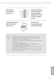
...) to the "FrontMic" Tab in our manual and chassis manual to Ground (GND). D. E. H170 Pro4 USB 3.0 Header (19-pin USB3_7_8) (see p.6, No. 23) GND PRESENCE# MIC_RET OUT_RET 1 OUT2_L J_SENSE OUT2_R MIC2_R MIC2_L This header is one header on this motherboard. B. English 21 To activate the front mic, go to OUT2_L. Connect Ground (GND...
...) to the "FrontMic" Tab in our manual and chassis manual to Ground (GND). D. E. H170 Pro4 USB 3.0 Header (19-pin USB3_7_8) (see p.6, No. 23) GND PRESENCE# MIC_RET OUT_RET 1 OUT2_L J_SENSE OUT2_R MIC2_R MIC2_L This header is one header on this motherboard. B. English 21 To activate the front mic, go to OUT2_L. Connect Ground (GND...

User Manual
Page 27
... a serial port module. vides an 8-pin ATX 12V power connector. English 22 Serial Port Header (9-pin COM1) (see p.6, No. 1) 8 5 This motherboard pro- Chassis Fan Connectors (4-pin CHA_FAN1) (see p.6, No. 17) (4-pin CHA_FAN2) (see p.6, No. 16) (4-pin CHA_FAN3) (see p.6, No. 4) 12 24 1 ...wire to Pin 1-3. GND FAN_VOLTAGE FAN_SPEED CPU Fan Connector (4-pin CPU_FAN1) (see p.6, No. 8) GND FAN_VOLTAGE_CONTROL FAN_SPEED FAN_SPEED_CONTROL This motherboard provides a 4-Pin CPU fan (Quiet Fan) connector. To use a 20-pin ATX power supply, please plug it to the ground pin.
... a serial port module. vides an 8-pin ATX 12V power connector. English 22 Serial Port Header (9-pin COM1) (see p.6, No. 1) 8 5 This motherboard pro- Chassis Fan Connectors (4-pin CHA_FAN1) (see p.6, No. 17) (4-pin CHA_FAN2) (see p.6, No. 16) (4-pin CHA_FAN3) (see p.6, No. 4) 12 24 1 ...wire to Pin 1-3. GND FAN_VOLTAGE FAN_SPEED CPU Fan Connector (4-pin CPU_FAN1) (see p.6, No. 8) GND FAN_VOLTAGE_CONTROL FAN_SPEED FAN_SPEED_CONTROL This motherboard provides a 4-Pin CPU fan (Quiet Fan) connector. To use a 20-pin ATX power supply, please plug it to the ground pin.

User Manual
Page 28
H170 Pro4 Chassis Intrusion Header (2-pin CI1) (see p.6, No. 21) 1 PCICLK FRAME PCIRST# LAD3 +3V LAD0 +3VSB GND This connector supports Trusted Platform Module (TPM) system, which ..., digital certificates, passwords, and data. GND SMB_CLK_MAIN SMB_DATA_MAIN LAD2 LAD1 GND S_PWRDWN# SERIRQ# GND TPM Header (17-pin TPMS1) (see p.6, No. 20) 1 GND Signal This motherboard supports CASE OPEN detection feature that detects if the chassis cove has been removed. English 23 PCIe Power Connector (4-pin PCIE_PWR1) (see p.6, No. 26) GND...
H170 Pro4 Chassis Intrusion Header (2-pin CI1) (see p.6, No. 21) 1 PCICLK FRAME PCIRST# LAD3 +3V LAD0 +3VSB GND This connector supports Trusted Platform Module (TPM) system, which ..., digital certificates, passwords, and data. GND SMB_CLK_MAIN SMB_DATA_MAIN LAD2 LAD1 GND S_PWRDWN# SERIRQ# GND TPM Header (17-pin TPMS1) (see p.6, No. 20) 1 GND Signal This motherboard supports CASE OPEN detection feature that detects if the chassis cove has been removed. English 23 PCIe Power Connector (4-pin PCIE_PWR1) (see p.6, No. 26) GND...

User Manual
Page 29
... details.) English 24 Please refer to use a AMD certified PSU. 2.7 CrossFireXTM and Quad CrossFireXTM Operation Guide This motherboard supports CrossFireXTM and Quad CrossFireXTM that allows you pair a 12-pipe CrossFireXTM Edition card with this motherboard. You should only use identical CrossFireXTM-ready graphics cards that are properly seated on the top of...
... details.) English 24 Please refer to use a AMD certified PSU. 2.7 CrossFireXTM and Quad CrossFireXTM Operation Guide This motherboard supports CrossFireXTM and Quad CrossFireXTM that allows you pair a 12-pipe CrossFireXTM Edition card with this motherboard. You should only use identical CrossFireXTM-ready graphics cards that are properly seated on the top of...

User Manual
Page 33
... by default. Hand tighten the standoff into the M.2 slot. Step 5 Align and gently insert the M.2 (NGFF) SSD module into the desired nut location on the motherboard. Skip Step 3 and 4 and go straight to Step 5 if you are going to be aware that the M.2 (NGFF) SSD module only fits in one orientation...
... by default. Hand tighten the standoff into the M.2 slot. Step 5 Align and gently insert the M.2 (NGFF) SSD module into the desired nut location on the motherboard. Skip Step 3 and 4 and go straight to Step 5 if you are going to be aware that the M.2 (NGFF) SSD module only fits in one orientation...
User Manual
Page 35
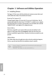
..., please download and install the following hot fix provided by Microsoft. Chapter 3 Software and Utilities Operation 3.1 Installing Drivers The Support CD that comes with the motherboard contains necessary drivers and useful utilities that the motherboard supports. Utilities Menu The Utilities Menu shows the application software that enhance the...
..., please download and install the following hot fix provided by Microsoft. Chapter 3 Software and Utilities Operation 3.1 Installing Drivers The Support CD that comes with the motherboard contains necessary drivers and useful utilities that the motherboard supports. Utilities Menu The Utilities Menu shows the application software that enhance the...
User Manual
Page 40
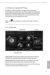
... and support utilities, such as USB Key, XFast LAN, XFast RAM and more . 35 English Click on your ASRock computer. You can optimize your system and keep your motherboard up to visit the website of the selected news and know more . Information Panel: The information panel in the... information. Hot News: The hot news section displays the various latest news. on the image to date simply with a few clicks. H170 Pro4 3.3 ASRock Live Update & APP Shop The ASRock Live Update & APP Shop is an online store for purchasing and downloading software applications for your desktop to access...
... and support utilities, such as USB Key, XFast LAN, XFast RAM and more . 35 English Click on your ASRock computer. You can optimize your system and keep your motherboard up to visit the website of the selected news and know more . Information Panel: The information panel in the... information. Hot News: The hot news section displays the various latest news. on the image to date simply with a few clicks. H170 Pro4 3.3 ASRock Live Update & APP Shop The ASRock Live Update & APP Shop is an online store for purchasing and downloading software applications for your desktop to access...
User Manual
Page 46
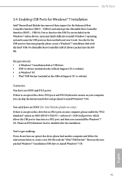
...Patcher". Please set PS/S Simulator back to install Windows® 7 OS. 41 English H170 Pro4 3.4 Enabling USB Ports for Windows® 7 Installation Intel® Braswell and Skylake has removed their motherboard won't work. Then use the new patched Windows® 7 installation USB drive to disabled...Windows® 7 installation disk or USB drive • USB 3.0 drivers (included in the ASRock Support CD or website) • A Windows® PC • Win7 USB Patcher (included in the ASRock Support CD or website) Scenarios You have an optical disc drive, please find it difficult to ...
...Patcher". Please set PS/S Simulator back to install Windows® 7 OS. 41 English H170 Pro4 3.4 Enabling USB Ports for Windows® 7 Installation Intel® Braswell and Skylake has removed their motherboard won't work. Then use the new patched Windows® 7 installation USB drive to disabled...Windows® 7 installation disk or USB drive • USB 3.0 drivers (included in the ASRock Support CD or website) • A Windows® PC • Win7 USB Patcher (included in the ASRock Support CD or website) Scenarios You have an optical disc drive, please find it difficult to ...
User Manual
Page 54
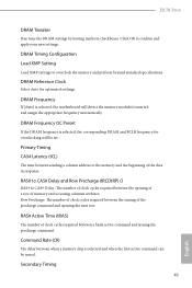
... to CAS# Delay and Row Precharge (tRCDtRP) O RAS# to the memory and the beginning of memory and accessing columns within it. H170 Pro4 DRAM Tweaker Fine tune the DRAM settings by leaving marks in response. DRAM Frequency OC Preset If the DRAM frequency is selected, the corresponding...clock cycles required between sending a column address to CAS# Delay : The number of clock cycles required between when a memory chip is selected, the motherboard will be issued. Command Rate (CR) The delay between the issuing of the precharge command and opening of a row of the data in checkboxes....
... to CAS# Delay and Row Precharge (tRCDtRP) O RAS# to the memory and the beginning of memory and accessing columns within it. H170 Pro4 DRAM Tweaker Fine tune the DRAM settings by leaving marks in response. DRAM Frequency OC Preset If the DRAM frequency is selected, the corresponding...clock cycles required between sending a column address to CAS# Delay : The number of clock cycles required between when a memory chip is selected, the motherboard will be issued. Command Rate (CR) The delay between the issuing of the precharge command and opening of a row of the data in checkboxes....
User Manual
Page 76
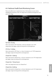
... temperature. CPU Fan 1 Setting Select a fan mode for CPU Fans 1, or choose Customize to set 5 CPU temperatures and assign a respective fan speed for Chassis Fan 1. H170 Pro4 4.6 Hardware Health Event Monitoring Screen This section allows you to set 5 CPU temperatures and assign a respective fan speed for each temperature. 71 English Chassis Fan... a fan mode for Chassis Fan 1, or choose Customize to monitor the status of the hardware on your system, including the parameters of the CPU temperature, motherboard temperature, fan speed and voltage.
... temperature. CPU Fan 1 Setting Select a fan mode for CPU Fans 1, or choose Customize to set 5 CPU temperatures and assign a respective fan speed for Chassis Fan 1. H170 Pro4 4.6 Hardware Health Event Monitoring Screen This section allows you to set 5 CPU temperatures and assign a respective fan speed for each temperature. 71 English Chassis Fan... a fan mode for Chassis Fan 1, or choose Customize to monitor the status of the hardware on your system, including the parameters of the CPU temperature, motherboard temperature, fan speed and voltage.

