

User Manual
Page 4
... I/O Panel 8 Chapter 2 Installation 10 2.1 Installing the CPU 11 2.2 Installing the CPU Fan and Heatsink 14 2.3 Installing Memory Modules (DIMM) 15 2.4 Expansion Slots (PCI Express Slots) 17 2.5 Jumpers Setup 18 2.6 Onboard Headers and Connectors 19 2.7 CrossFireXTM and Quad CrossFireXTM Operation Guide 24 2.7.1 Installing Two CrossFireXTM-Ready Graphics Cards 24 2.7.2 Driver Installation and Setup 26 2.8 M.2_SSD (NGFF) Module Installation Guide 27 Chapter 3 Software and Utilities Operation 30 3.1 Installing Drivers 30 3.2 A-Tuning 31 3.3 ASRock Live Update & APP...
... I/O Panel 8 Chapter 2 Installation 10 2.1 Installing the CPU 11 2.2 Installing the CPU Fan and Heatsink 14 2.3 Installing Memory Modules (DIMM) 15 2.4 Expansion Slots (PCI Express Slots) 17 2.5 Jumpers Setup 18 2.6 Onboard Headers and Connectors 19 2.7 CrossFireXTM and Quad CrossFireXTM Operation Guide 24 2.7.1 Installing Two CrossFireXTM-Ready Graphics Cards 24 2.7.2 Driver Installation and Setup 26 2.8 M.2_SSD (NGFF) Module Installation Guide 27 Chapter 3 Software and Utilities Operation 30 3.1 Installing Drivers 30 3.2 A-Tuning 31 3.3 ASRock Live Update & APP...

User Manual
Page 5
... BIOS & Drivers 39 3.3.4 Setting 40 3.4 Enabling USB Ports for Windows® 7 Installation 41 Chapter 4 UEFI SETUP UTILITY 44 4.1 Introduction 44 4.1.1 UEFI Menu Bar 44 4.1.2 Navigation Keys 45 4.2 Main Screen 46 4.3 OC Tweaker Screen 47 4.4 Advanced Screen 56 4.4.1 CPU Configuration 57 4.4.2 Chipset Configuration 59 4.4.3 Storage Configuration 61 4.4.4 Super IO Configuration 62 4.4.5 ACPI Configuration 63 4.4.6 USB Configuration 65 4.4.7 Trusted Computing 66 4.5 Tools 67 4.6 Hardware Health Event Monitoring Screen 71 4.7 Security Screen 73 4.8 Boot...
... BIOS & Drivers 39 3.3.4 Setting 40 3.4 Enabling USB Ports for Windows® 7 Installation 41 Chapter 4 UEFI SETUP UTILITY 44 4.1 Introduction 44 4.1.1 UEFI Menu Bar 44 4.1.2 Navigation Keys 45 4.2 Main Screen 46 4.3 OC Tweaker Screen 47 4.4 Advanced Screen 56 4.4.1 CPU Configuration 57 4.4.2 Chipset Configuration 59 4.4.3 Storage Configuration 61 4.4.4 Super IO Configuration 62 4.4.5 ACPI Configuration 63 4.4.6 USB Configuration 65 4.4.7 Trusted Computing 66 4.5 Tools 67 4.6 Hardware Health Event Monitoring Screen 71 4.7 Security Screen 73 4.8 Boot...
User Manual
Page 6
...; 2 x Serial ATA (SATA) Data Cables (Optional) • 1 x I/O Panel Shield • 1 x Screw for purchasing ASRock H170 Pro4 motherboard, a reliable motherboard produced under ASRock's consistently stringent quality control. In case any modifications of the motherboard and step-by-step installation guides. Chapter 3 contains the operation guide of the BIOS setup. You may find the latest VGA cards and CPU support list on ASRock's website without notice. It delivers excellent performance with robust design conforming to ASRock's commitment to change...
...; 2 x Serial ATA (SATA) Data Cables (Optional) • 1 x I/O Panel Shield • 1 x Screw for purchasing ASRock H170 Pro4 motherboard, a reliable motherboard produced under ASRock's consistently stringent quality control. In case any modifications of the motherboard and step-by-step installation guides. Chapter 3 contains the operation guide of the BIOS setup. You may find the latest VGA cards and CPU support list on ASRock's website without notice. It delivers excellent performance with robust design conforming to ASRock's commitment to change...
User Manual
Page 9
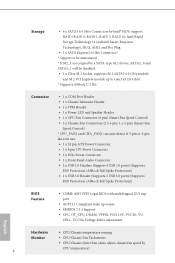
... 5, RAID 10, Intel Rapid Storage Technology 14 and Intel Smart Response Technology), NCQ, AHCI and Hot Plug • 1 x SATA Express 10 Gb/s Connector* * Support to Gen3 x4 (32 Gb/s) * Supports ASRock U.2 Kit Connector • 1 x COM Port Header • 1 x Chassis Intrusion Header • 1 x TPM Header • 1 x Power LED and Speaker Header • 1 x CPU Fan Connector (4-pin) (Smart Fan Speed Control) • 3 x Chassis Fan Connectors (2 x 4-pin, 1 x 3-pin) (Smart Fan Speed Control) * CPU_FAN1 and CHA_FAN1 can auto detect if 3-pin or 4-pin fan is in use. • 1 x 24 pin ATX Power...
... 5, RAID 10, Intel Rapid Storage Technology 14 and Intel Smart Response Technology), NCQ, AHCI and Hot Plug • 1 x SATA Express 10 Gb/s Connector* * Support to Gen3 x4 (32 Gb/s) * Supports ASRock U.2 Kit Connector • 1 x COM Port Header • 1 x Chassis Intrusion Header • 1 x TPM Header • 1 x Power LED and Speaker Header • 1 x CPU Fan Connector (4-pin) (Smart Fan Speed Control) • 3 x Chassis Fan Connectors (2 x 4-pin, 1 x 3-pin) (Smart Fan Speed Control) * CPU_FAN1 and CHA_FAN1 can auto detect if 3-pin or 4-pin fan is in use. • 1 x 24 pin ATX Power...
User Manual
Page 10
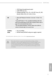
... should be done at your system. English 5 H170 Pro4 OS Certifications • CPU/Chassis Fan multi-speed control • CASE OPEN detection • Voltage monitoring: +12V, +5V, +3.3V, CPU Vcore, GT_CPU, DRAM, VPPM, PCH 1.0V, VCCIO, VCCSA • Microsoft® Windows® 10 64-bit / 8.1 64-bit / 7 32-bit / 7 64bit * To install Windows® 7 OS, a modified installation disk with overclocking, including adjusting the setting in the BIOS, applying Untied Overclocking Technology, or using third-party overclocking tools.
... should be done at your system. English 5 H170 Pro4 OS Certifications • CPU/Chassis Fan multi-speed control • CASE OPEN detection • Voltage monitoring: +12V, +5V, +3.3V, CPU Vcore, GT_CPU, DRAM, VPPM, PCH 1.0V, VCCIO, VCCSA • Microsoft® Windows® 10 64-bit / 8.1 64-bit / 7 32-bit / 7 64bit * To install Windows® 7 OS, a modified installation disk with overclocking, including adjusting the setting in the BIOS, applying Untied Overclocking Technology, or using third-party overclocking tools.

User Manual
Page 22
... supply is switched off or the power cord is used for PCI Express x4 lane width graphics cards. PCIE4 (PCIe 3.0 x16 slot) is unplugged. PCIe Slot Configurations Single Graphics Card PCIE2 x16 PCIE4 N/A Two Graphics Cards in CrossFireXTM Mode x16 x4 For a better thermal environment, please connect a chassis fan to the motherboard's chassis fan connector (CHA_FAN1, CHA_FAN2 or CHA_FAN3) when using multiple graphics cards. English 17 PCIe slots: PCIE1 (PCIe 3.0 x1 slot) is used for the card before you start the installation. PCIE5 (PCIe 3.0 x1 slot) is used for PCI Express...
... supply is switched off or the power cord is used for PCI Express x4 lane width graphics cards. PCIE4 (PCIe 3.0 x16 slot) is unplugged. PCIe Slot Configurations Single Graphics Card PCIE2 x16 PCIE4 N/A Two Graphics Cards in CrossFireXTM Mode x16 x4 For a better thermal environment, please connect a chassis fan to the motherboard's chassis fan connector (CHA_FAN1, CHA_FAN2 or CHA_FAN3) when using multiple graphics cards. English 17 PCIe slots: PCIE1 (PCIe 3.0 x1 slot) is used for the card before you start the installation. PCIE5 (PCIe 3.0 x1 slot) is used for PCI Express...

User Manual
Page 23
... CMOS, the case open may be cleared only if the CMOS battery is placed on CLRMOS1 for 15 seconds, use a jumper cap to default setup, please turn off the computer and unplug the power cord from the power supply. However, please do the clear-CMOS action. 2.5 Jumpers Setup The illustration shows how jumpers are "Short" when a jumper cap is removed. The illustration shows a 3-pin jumper whose pin1 and pin2 are setup. Please adjust the BIOS option "Clear...
... CMOS, the case open may be cleared only if the CMOS battery is placed on CLRMOS1 for 15 seconds, use a jumper cap to default setup, please turn off the computer and unplug the power cord from the power supply. However, please do the clear-CMOS action. 2.5 Jumpers Setup The illustration shows how jumpers are "Short" when a jumper cap is removed. The illustration shows a 3-pin jumper whose pin1 and pin2 are setup. Please adjust the BIOS option "Clear...

User Manual
Page 28
... removed. This feature requires a chassis with chassis intrusion detection design. H170 Pro4 Chassis Intrusion Header (2-pin CI1) (see p.6, No. 21) 1 PCICLK FRAME PCIRST# LAD3 +3V LAD0 +3VSB GND This connector supports Trusted Platform Module (TPM) system, which can securely store keys, digital certificates, passwords, and data. PCIe Power Connector (4-pin PCIE_PWR1) (see p.6, No. 26) GND +12V DETECT Please connect a 4 pin molex power cable to this connector when more than three graphics cards are installed...
... removed. This feature requires a chassis with chassis intrusion detection design. H170 Pro4 Chassis Intrusion Header (2-pin CI1) (see p.6, No. 21) 1 PCICLK FRAME PCIRST# LAD3 +3V LAD0 +3VSB GND This connector supports Trusted Platform Module (TPM) system, which can securely store keys, digital certificates, passwords, and data. PCIe Power Connector (4-pin PCIE_PWR1) (see p.6, No. 26) GND +12V DETECT Please connect a 4 pin molex power cable to this connector when more than three graphics cards are installed...

User Manual
Page 29
... installation guide. 2.7.1 Installing Two CrossFireXTM-Ready Graphics Cards Step 1 Insert one graphics card into PCIE2 slot and the other graphics card to AMD graphics card manuals for details.) English 24 Make sure that the cards are AMD certified. 2. Make sure that your power supply unit (PSU) can provide at least the minimum power your graphics card driver supports AMD CrossFireXTM technology. Download the drivers from the AMD's website: www.amd.com 3. Please refer to PCIE4 slot. CrossFire Bridge Step 2 Connect two graphics cards...
... installation guide. 2.7.1 Installing Two CrossFireXTM-Ready Graphics Cards Step 1 Insert one graphics card into PCIE2 slot and the other graphics card to AMD graphics card manuals for details.) English 24 Make sure that the cards are AMD certified. 2. Make sure that your power supply unit (PSU) can provide at least the minimum power your graphics card driver supports AMD CrossFireXTM technology. Download the drivers from the AMD's website: www.amd.com 3. Please refer to PCIE4 slot. CrossFire Bridge Step 2 Connect two graphics cards...
User Manual
Page 31
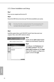
... 3 Install the required drivers and CATALYST Control Center then restart your graphics card and click Apply. English 26 We recommend using this utility to uninstall any VGA drivers installed in the Windows® system tray. Please check AMD's website for AMD driver updates. The Catalyst Uninstaller is an optional download. Step 5 In the left pane, click Performance and then AMD CrossFireXTM. Then select Enable AMD CrossFireX and click Apply. AMD Catalyst Control...
... 3 Install the required drivers and CATALYST Control Center then restart your graphics card and click Apply. English 26 We recommend using this utility to uninstall any VGA drivers installed in the Windows® system tray. Please check AMD's website for AMD driver updates. The Catalyst Uninstaller is an optional download. Step 5 In the left pane, click Performance and then AMD CrossFireXTM. Then select Enable AMD CrossFireX and click Apply. AMD Catalyst Control...
User Manual
Page 35
... auto-detected and listed on the file "ASRSETUP.EXE" in your CD-ROM drive. Utilities Menu The Utilities Menu shows the application software that enhance the motherboard's features. "KB2720599": http://support.microsoft.com/kb/2720599/en-us 30 English If the Main Menu does not appear automatically, locate and double click on the support CD driver page. Drivers Menu The drivers compatible to display the menu. Therefore, the drivers you install can work properly. Running The Support...
... auto-detected and listed on the file "ASRSETUP.EXE" in your CD-ROM drive. Utilities Menu The Utilities Menu shows the application software that enhance the motherboard's features. "KB2720599": http://support.microsoft.com/kb/2720599/en-us 30 English If the Main Menu does not appear automatically, locate and double click on the support CD driver page. Drivers Menu The drivers compatible to display the menu. Therefore, the drivers you install can work properly. Running The Support...
User Manual
Page 46
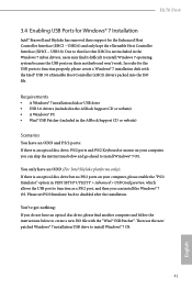
... install Windows 7 operating system because the USB ports on their support for the Enhanced Host Controller Interface (EHCI - H170 Pro4 3.4 Enabling USB Ports for Windows® 7 Installation Intel® Braswell and Skylake has removed their motherboard won't work. Then use the new patched Windows® 7 installation USB drive to disabled after the installation. Requirements • A Windows® 7 installation disk or USB drive • USB 3.0 drivers (included in the ASRock Support CD or website) • A Windows® PC • Win7 USB Patcher (included in the ASRock Support...
... install Windows 7 operating system because the USB ports on their support for the Enhanced Host Controller Interface (EHCI - H170 Pro4 3.4 Enabling USB Ports for Windows® 7 Installation Intel® Braswell and Skylake has removed their motherboard won't work. Then use the new patched Windows® 7 installation USB drive to disabled after the installation. Requirements • A Windows® 7 installation disk or USB drive • USB 3.0 drivers (included in the ASRock Support CD or website) • A Windows® PC • Win7 USB Patcher (included in the ASRock Support...
User Manual
Page 47
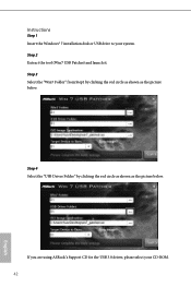
Step 2 Extract the tool (Win7 USB Patcher) and launch it. Step 3 Select the "Win7 Folder" from Step1 by clicking the red circle as shown as the picture below . If you are using ASRock's Support CD for the USB 3.0 driver, please select your system. Instructions Step 1 Insert the Windows® 7 installation disk or USB drive to your CD-ROM. 42 English Step 4 Select the "USB Driver Folder" by clicking the red circle as shown as the picture below .
Step 2 Extract the tool (Win7 USB Patcher) and launch it. Step 3 Select the "Win7 Folder" from Step1 by clicking the red circle as shown as the picture below . If you are using ASRock's Support CD for the USB 3.0 driver, please select your system. Instructions Step 1 Insert the Windows® 7 installation disk or USB drive to your CD-ROM. 42 English Step 4 Select the "USB Driver Folder" by clicking the red circle as shown as the picture below .

User Manual
Page 65
... external graphics card is allocated to enable onboard HD audio and automatically disable it when a sound card is idle for all times. Deep Sleep Configure deep sleep mode for power saving when the computer is shut down the render unit when the GPU is installed. Front Panel Enable/disable front panel HD audio. PCH DMI ASPM Support This option enables/disables the ASPM support for lower power consumption. Set to Auto to the integrated graphics processor when the system boots...
... external graphics card is allocated to enable onboard HD audio and automatically disable it when a sound card is idle for all times. Deep Sleep Configure deep sleep mode for power saving when the computer is shut down the render unit when the GPU is installed. Front Panel Enable/disable front panel HD audio. PCH DMI ASPM Support This option enables/disables the ASPM support for lower power consumption. Set to Auto to the integrated graphics processor when the system boots...

User Manual
Page 67
PS2 Y-Cable Enable the PS2 Y-Cable or set this option to Auto. 62 English Serial Port Address Select the address of the Serial port. 4.4.4 Super IO Configuration Serial Port Enable or disable the Serial port.
PS2 Y-Cable Enable the PS2 Y-Cable or set this option to Auto. 62 English Serial Port Address Select the address of the Serial port. 4.4.4 Super IO Configuration Serial Port Enable or disable the Serial port.
User Manual
Page 72
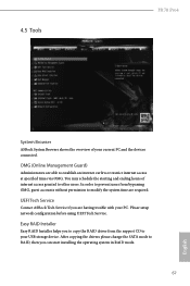
... current PC and the devices connected. After copying the drivers please change the SATA mode to RAID, then you to copy the RAID driver from bypassing OMG, guest accounts without permission to modify the system time are required. Please setup network configuration before using UEFI Tech Service. UEFI Tech Service Contact ASRock Tech Service if you are able to establish an internet curfew or restrict internet access at specified times...
... current PC and the devices connected. After copying the drivers please change the SATA mode to RAID, then you to copy the RAID driver from bypassing OMG, guest accounts without permission to modify the system time are required. Please setup network configuration before using UEFI Tech Service. UEFI Tech Service Contact ASRock Tech Service if you are able to establish an internet curfew or restrict internet access at specified times...
User Manual
Page 73
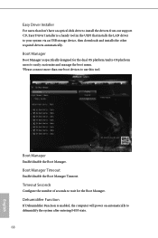
... easily customize and manage the boot menu. *Please connect more than one boot devices to use this tool. Boot Manager Timeout Enable/disable the Boot Manager Timeout. Boot Manager Enable/disable the Boot Manager. Easy Driver Installer For users that don't have an optical disk drive to install the drivers from our support CD, Easy Driver Installer is a handy tool in the UEFI that installs the LAN driver to dehumidify the system after entering S4/S5 state. 68 English...
... easily customize and manage the boot menu. *Please connect more than one boot devices to use this tool. Boot Manager Timeout Enable/disable the Boot Manager Timeout. Boot Manager Enable/disable the Boot Manager. Easy Driver Installer For users that don't have an optical disk drive to install the drivers from our support CD, Easy Driver Installer is a handy tool in the UEFI that installs the LAN driver to dehumidify the system after entering S4/S5 state. 68 English...
User Manual
Page 74
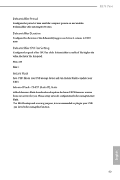
... USB storage device and run Instant Flash to plug in your UEFI. Dehumidifier Duration Configure the duration of the CPU fan while Dehumidifier is recommended to update your USB pen drive before using this function. 69 English Please setup network configuration before using Internet Flash. *For BIOS backup and recovery purpose, it returns to S4/S5 state. H170 Pro4 Dehumidifier Period Configure the period of time until the computer powers on and enables Dehumidifier after entering...
... USB storage device and run Instant Flash to plug in your UEFI. Dehumidifier Duration Configure the duration of the CPU fan while Dehumidifier is recommended to update your USB pen drive before using this function. 69 English Please setup network configuration before using Internet Flash. *For BIOS backup and recovery purpose, it returns to S4/S5 state. H170 Pro4 Dehumidifier Period Configure the period of time until the computer powers on and enables Dehumidifier after entering...

User Manual
Page 75
UEFI Download Server Select a server to configure internet connection settings for Internet Flash. Internet Setting Enable or disable sound effects in the setup utility. Network Configuration Use this to download the UEFI firmware. 70 English
UEFI Download Server Select a server to configure internet connection settings for Internet Flash. Internet Setting Enable or disable sound effects in the setup utility. Network Configuration Use this to download the UEFI firmware. 70 English

User Manual
Page 78
... may set or change the password for the administrator account. Users are unable to use discrete TPM Module. 73 English Secure Boot Use this option to change the password for the user account. Disable this item to remove the password. H170 Pro4 4.7 Security Screen In this section you may also clear the user password. Leave it blank and press enter to enable or disable support for Windows 8.1 Secure Boot. User Password Set or change the settings in the UEFI Setup Utility. Intel(R) Platform Trust Technology Enable/disable...
... may set or change the password for the administrator account. Users are unable to use discrete TPM Module. 73 English Secure Boot Use this option to change the password for the user account. Disable this item to remove the password. H170 Pro4 4.7 Security Screen In this section you may also clear the user password. Leave it blank and press enter to enable or disable support for Windows 8.1 Secure Boot. User Password Set or change the settings in the UEFI Setup Utility. Intel(R) Platform Trust Technology Enable/disable...


