
User Manual
Page 3
... Slots (PCI and PCI Express Slots 18 2.7 Jumpers Setup 19 2.8 Onboard Headers and Connectors 20 2.9 SATAII Hard Disk Setup Guide 24 2.10 Serial ATA (SATA) / Serial ATAII (SATAII) Hard Disks Installation 25 2.11 Driver Installation Guide 25 2.12 Untied Overclocking Technology 25 3 BIOS SETUP UTILITY 26 3.1 Introduction 26 3.1.1 BIOS Menu Bar 26 3.1.2 Navigation Keys 27 3.2 Main Screen 27 3.3 OC Tweaker Screen 28 3.4 Advanced Screen 32 3.4.1 CPU Configuration 33 3.4.2 Chipset Configuration 35 3.4.3 ACPI Configuration 40 3.4.4 Storage Configuration 41 3.4.5 PCIPnP Configuration...
... Slots (PCI and PCI Express Slots 18 2.7 Jumpers Setup 19 2.8 Onboard Headers and Connectors 20 2.9 SATAII Hard Disk Setup Guide 24 2.10 Serial ATA (SATA) / Serial ATAII (SATAII) Hard Disks Installation 25 2.11 Driver Installation Guide 25 2.12 Untied Overclocking Technology 25 3 BIOS SETUP UTILITY 26 3.1 Introduction 26 3.1.1 BIOS Menu Bar 26 3.1.2 Navigation Keys 27 3.2 Main Screen 27 3.3 OC Tweaker Screen 28 3.4 Advanced Screen 32 3.4.1 CPU Configuration 33 3.4.2 Chipset Configuration 35 3.4.3 ACPI Configuration 40 3.4.4 Storage Configuration 41 3.4.5 PCIPnP Configuration...

User Manual
Page 9
... user to EuP, the total AC power of overclocking settings. Just launch this utility, you can save the new BIOS file to save your friends! Please be under 1.00W in off mode condition. Frequencies other than 50% under Windows® environment. Please visit our website for Energy Using Product, was a provision regulated by hardware monitor function and overclock your BIOS only in Flash ROM. ASRock Instant Flash is a BIOS flash utility...
... user to EuP, the total AC power of overclocking settings. Just launch this utility, you can save the new BIOS file to save your friends! Please be under 1.00W in off mode condition. Frequencies other than 50% under Windows® environment. Please visit our website for Energy Using Product, was a provision regulated by hardware monitor function and overclock your BIOS only in Flash ROM. ASRock Instant Flash is a BIOS flash utility...
User Manual
Page 21
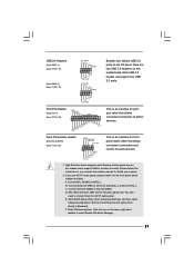
... four default USB 2.0 ports on the chassis must support HDA to [Enabled]. High Definition Audio supports Jack Sensing, but the panel wire on the I/O panel, there are for AC'97 audio panel. Connect Mic_IN (MIC) to Ground (GND). D. E. Enter BIOS Setup Utility. F. B. Connect Ground (GND) to MIC2_L. Click the icon on this motherboard. Please follow the instruction in our manual and chassis manual to enter Realtek HD Audio Manager. 21 Enter Windows system. MIC_RET and OUT_RET are two USB 2.0 headers on...
... four default USB 2.0 ports on the chassis must support HDA to [Enabled]. High Definition Audio supports Jack Sensing, but the panel wire on the I/O panel, there are for AC'97 audio panel. Connect Mic_IN (MIC) to Ground (GND). D. E. Enter BIOS Setup Utility. F. B. Connect Ground (GND) to MIC2_L. Click the icon on this motherboard. Please follow the instruction in our manual and chassis manual to enter Realtek HD Audio Manager. 21 Enter Windows system. MIC_RET and OUT_RET are two USB 2.0 headers on...

User Manual
Page 24
... updates. 24 otherwise, your reference. In order to enable SATAII function, please follow the below SATAII hard disk setup guide. SAMSUNG 7531 8642 If pin 3 and pin 4 are shorted, SATA 1.5Gb/s will be at SATAII mode. On the other hand, if you want to enable SATAII 3.0Gb/s, please remove the jumpers from pin 5 and pin 6. 2 . 9 SATAII Hard Disk Setup Guide Before installing SATAII hard disk to your SATAII hard disk to SATAII mode in advance; Some default setting...
... updates. 24 otherwise, your reference. In order to enable SATAII function, please follow the below SATAII hard disk setup guide. SAMSUNG 7531 8642 If pin 3 and pin 4 are shorted, SATA 1.5Gb/s will be at SATAII mode. On the other hand, if you want to enable SATAII 3.0Gb/s, please remove the jumpers from pin 5 and pin 6. 2 . 9 SATAII Hard Disk Setup Guide Before installing SATAII hard disk to your SATAII hard disk to SATAII mode in advance; Some default setting...

User Manual
Page 25
... install the SATA / SATAII hard disks. Before you apply Untied Overclocking Technology. 25 2 . 1 0 Serial ATA (SATA) / Serial ATAII (SATAII) Hard Disks Installation This motherboard adopts Intel® ICH7 south bridge chipset that FSB can be auto-detected and listed on page 8 for internal storage devices. You may install SATA / SATAII hard disks on this motherboard for the possible overclocking risk before you enable Untied Overclocking function, please enter "Overclock Mode" option of the SATA data cable to fixed PCI / PCIE buses. STEP 3: Connect one end of BIOS setup...
... install the SATA / SATAII hard disks. Before you apply Untied Overclocking Technology. 25 2 . 1 0 Serial ATA (SATA) / Serial ATAII (SATAII) Hard Disks Installation This motherboard adopts Intel® ICH7 south bridge chipset that FSB can be auto-detected and listed on page 8 for internal storage devices. You may install SATA / SATAII hard disks on this motherboard for the possible overclocking risk before you enable Untied Overclocking function, please enter "Overclock Mode" option of the SATA data cable to fixed PCI / PCIE buses. STEP 3: Connect one end of BIOS setup...
User Manual
Page 28
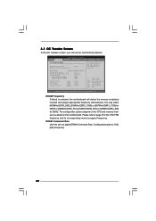
.... DRAM Frequency If [Auto] is selected, the motherboard will detect the memory module(s) inserted and assigns appropriate frequency automatically. For FSB1333 CPU: FSB1 = 2-3 Ratio Status Unlocked (Min:06, Max:17) Ratio CMOS Setting 17 [17] Intel (R) SpeedStep (tm) tech. [Disabled] Overclock Mode [Auto] CPU Frequency (MHz) [200] PCIE Frequency (MHz) [100] DRAM Voltage NB Voltage VTT Voltage GTLRef Voltage 1.53V 1.23V 1.20V 0.63Vtt [Auto] [Auto] [Auto] [Auto] Select Screen Select Item Enter Go to Sub Screen F1 General Help F9 Load Defaults...
.... DRAM Frequency If [Auto] is selected, the motherboard will detect the memory module(s) inserted and assigns appropriate frequency automatically. For FSB1333 CPU: FSB1 = 2-3 Ratio Status Unlocked (Min:06, Max:17) Ratio CMOS Setting 17 [17] Intel (R) SpeedStep (tm) tech. [Disabled] Overclock Mode [Auto] CPU Frequency (MHz) [200] PCIE Frequency (MHz) [100] DRAM Voltage NB Voltage VTT Voltage GTLRef Voltage 1.53V 1.23V 1.20V 0.63Vtt [Auto] [Auto] [Auto] [Auto] Select Screen Select Item Enter Go to Sub Screen F1 General Help F9 Load Defaults...

User Manual
Page 30
... Overclock Mode. DRAM Voltage Use this to [2.73V]. If the CPU you adopt supports EIST (Intel (R) SpeedStep(tm) tech.), and you install Windows® VistaTM and want to enable this function, please set the "Power Schemes" as "Portable/Laptop" to adjust the ratio value, please disable the option " Intel (R) SpeedStep(tm) tech." Intel (R) SpeedStep(tm) tech. Configuration options: [Auto], [Manual] and [Optimized]. Configuration options: [Auto], [1.05V] to enable power savings. The default value is [Auto...
... Overclock Mode. DRAM Voltage Use this to [2.73V]. If the CPU you adopt supports EIST (Intel (R) SpeedStep(tm) tech.), and you install Windows® VistaTM and want to enable this function, please set the "Power Schemes" as "Portable/Laptop" to adjust the ratio value, please disable the option " Intel (R) SpeedStep(tm) tech." Intel (R) SpeedStep(tm) tech. Configuration options: [Auto], [Manual] and [Optimized]. Configuration options: [Auto], [1.05V] to enable power savings. The default value is [Auto...

User Manual
Page 33
.... CPU Frequency (MHz) Use this motherboard. Spread Spectrum This item should always be [Auto] for better system stability. The C1 state is [Auto]. Configuration options: [Auto], [Manual] and [Optimized]. Ratio CMOS Setting If the ratio status is a read-only item, which displays whether the ratio status of this option to adjust the ratio value, please disable the option " Intel (R) SpeedStep(tm) tech." 3.4.1 CPU Configuration BIOS SETUP UTILITY Advanced CPU Configuration Overclock Mode CPU Frequency (MHz) PCIE Frequency (MHz) Boot Failure Guard...
.... CPU Frequency (MHz) Use this motherboard. Spread Spectrum This item should always be [Auto] for better system stability. The C1 state is [Auto]. Configuration options: [Auto], [Manual] and [Optimized]. Ratio CMOS Setting If the ratio status is a read-only item, which displays whether the ratio status of this option to adjust the ratio value, please disable the option " Intel (R) SpeedStep(tm) tech." 3.4.1 CPU Configuration BIOS SETUP UTILITY Advanced CPU Configuration Overclock Mode CPU Frequency (MHz) PCIE Frequency (MHz) Boot Failure Guard...

User Manual
Page 34
... to enable this function, please set to [Enabled], a VMM (Virtual Machine Architecture) can switch between multiple frequency and voltage points to [Enabled]. This option will be hidden if the current CPU does not support CPU Thermal Throttling. No-Excute Memory Protection No-Execution (NX) Memory Protection Technology is set this function may select [Enabled] to enable P4 CPU internal thermal control mechanism to keep the CPU from being used by Vanderpool Technology. Configuration options: [Auto], [Enabled] and [Disabled]. This...
... to enable this function, please set to [Enabled], a VMM (Virtual Machine Architecture) can switch between multiple frequency and voltage points to [Enabled]. This option will be hidden if the current CPU does not support CPU Thermal Throttling. No-Excute Memory Protection No-Execution (NX) Memory Protection Technology is set this function may select [Enabled] to enable P4 CPU internal thermal control mechanism to keep the CPU from being used by Vanderpool Technology. Configuration options: [Auto], [Enabled] and [Disabled]. This...

User Manual
Page 39
... power savings. If you can also choose our Intelligent Energy Saver utility to enable this option to select [Onboard], [PCI] or [PCI Express] as the boot graphic adapter priority. Share Memory This allows you to adjust DVMT mode. Configuration options: [Disabled] and [Lite]. In DVMT mode, the graphics driver allocates memory as [DVMT Mode]. Configuration options: [Enabled] and [Disabled]. The default value is [Disabled]. DVMT Mode Select Use this function. Besides the BIOS option, you want to adjust PAVP mode. The default...
... power savings. If you can also choose our Intelligent Energy Saver utility to enable this option to select [Onboard], [PCI] or [PCI Express] as the boot graphic adapter priority. Share Memory This allows you to adjust DVMT mode. Configuration options: [Disabled] and [Lite]. In DVMT mode, the graphics driver allocates memory as [DVMT Mode]. Configuration options: [Enabled] and [Disabled]. The default value is [Disabled]. DVMT Mode Select Use this function. Besides the BIOS option, you want to adjust PAVP mode. The default...

User Manual
Page 43
PCI IDE BusMaster Use this item to maximize the IDE hard disk data transfer rate. 3.4.5 PCIPnP Configuration BIOS SETUP UTILITY Advanced Advanced PCI / PnP Settings PCI Latency Timer PCI IDE BusMaster [32] [Enabled] Value in units of PCI clocks for PCI device latency timer register. +F1 F9 F10 ESC Select Screen Select Item Change Option General Help Load Defaults Save and Exit Exit v02.54 (C) Copyright 1985-2005, American Megatrends, Inc. Configuration options: [Disabled], [Auto], [Enabled]. 32-Bit Data Transfer Use this item...
PCI IDE BusMaster Use this item to maximize the IDE hard disk data transfer rate. 3.4.5 PCIPnP Configuration BIOS SETUP UTILITY Advanced Advanced PCI / PnP Settings PCI Latency Timer PCI IDE BusMaster [32] [Enabled] Value in units of PCI clocks for PCI device latency timer register. +F1 F9 F10 ESC Select Screen Select Item Change Option General Help Load Defaults Save and Exit Exit v02.54 (C) Copyright 1985-2005, American Megatrends, Inc. Configuration options: [Disabled], [Auto], [Enabled]. 32-Bit Data Transfer Use this item...

User Manual
Page 45
...] to enter OS. [BIOS Setup Only] - If you have USB compatibility issue, it is [Enabled]. 3.4.7 USB Configuration BIOS SETUP UTILITY Advanced USB Configuration USB Controller USB 2.0 Support Legacy USB Support [Enabled] [Enabled] [Enabled] To enable or disable the onboard USB controllers. +F1 F9 F10 ESC Select Screen Select Item Change Option General Help Load Defaults Save and Exit Exit v02.54 (C) Copyright 1985-2005, American Megatrends, Inc. USB 2.0 Support Use this item to select legacy support for the details of USB controller. Legacy USB Support Use this option to enable or...
...] to enter OS. [BIOS Setup Only] - If you have USB compatibility issue, it is [Enabled]. 3.4.7 USB Configuration BIOS SETUP UTILITY Advanced USB Configuration USB Controller USB 2.0 Support Legacy USB Support [Enabled] [Enabled] [Enabled] To enable or disable the onboard USB controllers. +F1 F9 F10 ESC Select Screen Select Item Change Option General Help Load Defaults Save and Exit Exit v02.54 (C) Copyright 1985-2005, American Megatrends, Inc. USB 2.0 Support Use this item to select legacy support for the details of USB controller. Legacy USB Support Use this option to enable or...

User Manual
Page 48
...Copyright 1985-2005, American Megatrends, Inc. 48 Boot From Onboard LAN Use this option to select logo in POST screen. The default value is set or change the supervisor/user password for the system. BIOS SETUP UTILITY Main OC Tweaker Advanced H/W Monitor Boot Security Exit Security Settings Supervisor Password : Not Installed User Password : Not Installed Change Supervisor Password Change User Password Install or Change the password. Configuration options: [Auto], [EuP], [Scenery] and [ASRock]. Boot Logo Use this item to enable or disable the Boot From Onboard LAN feature.
...Copyright 1985-2005, American Megatrends, Inc. 48 Boot From Onboard LAN Use this option to select logo in POST screen. The default value is set or change the supervisor/user password for the system. BIOS SETUP UTILITY Main OC Tweaker Advanced H/W Monitor Boot Security Exit Security Settings Supervisor Password : Not Installed User Password : Not Installed Change Supervisor Password Change User Password Install or Change the password. Configuration options: [Auto], [EuP], [Scenery] and [ASRock]. Boot Logo Use this item to enable or disable the Boot From Onboard LAN feature.
User Manual
Page 50
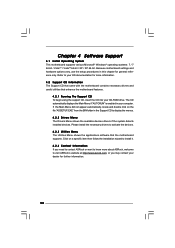
.... Refer to display the menus. 4.2.2 Drivers Menu The Drivers Menu shows the available devices drivers if the system detects installed devices. or you need to contact ASRock or want to visit ASRock's website at http://www.asrock.com; Chapter 4 Software Support 4.1 Install Operating System This motherboard supports various Microsoft® Windows® operating systems: 7 / 7 64-bit / VistaTM / VistaTM 64-bit / XP / XP 64-bit. Because motherboard settings and hardware options vary, use the setup procedures in...
.... Refer to display the menus. 4.2.2 Drivers Menu The Drivers Menu shows the available devices drivers if the system detects installed devices. or you need to contact ASRock or want to visit ASRock's website at http://www.asrock.com; Chapter 4 Software Support 4.1 Install Operating System This motherboard supports various Microsoft® Windows® operating systems: 7 / 7 64-bit / VistaTM / VistaTM 64-bit / XP / XP 64-bit. Because motherboard settings and hardware options vary, use the setup procedures in...
Quick Installation Guide
Page 6
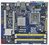
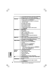
... FAN connector - 24 pin ATX power connector - 4 pin 12V power connector - ASRock OC DNA (see CAUTION 10) - Boot Failure Guard (B.F.G.) Hardware - Chassis Temperature Sensing - - 1 x RJ-45 LAN Port with LED (ACT/LINK LED and SPEED LED) - AMI Legal BIOS - ACPI 1.1 Compliance Wake Up Events - Instant Boot - CPU Temperature Sensing Monitor - Intelligent Energy Saver (see CAUTION 12) - Voltage Monitoring: +12V, +5V, +3.3V, Vcore OS - SMBIOS 2.3.1 Support - ASRock OC Tuner (see CAUTION 15) 6 ASRock G41C-VS Motherboard EuP Ready (EuP ready power supply...
... FAN connector - 24 pin ATX power connector - 4 pin 12V power connector - ASRock OC DNA (see CAUTION 10) - Boot Failure Guard (B.F.G.) Hardware - Chassis Temperature Sensing - - 1 x RJ-45 LAN Port with LED (ACT/LINK LED and SPEED LED) - AMI Legal BIOS - ACPI 1.1 Compliance Wake Up Events - Instant Boot - CPU Temperature Sensing Monitor - Intelligent Energy Saver (see CAUTION 12) - Voltage Monitoring: +12V, +5V, +3.3V, Vcore OS - SMBIOS 2.3.1 Support - ASRock OC Tuner (see CAUTION 15) 6 ASRock G41C-VS Motherboard EuP Ready (EuP ready power supply...
Quick Installation Guide
Page 7
... Overclocking Technology" on page 24 of "User Manual" in the support CD to adjust your system. Please refer to SATAII connector, please read the installation guide of your SATAII hard disk drive to SATAII connector directly. 8. For Windows® OS with overclocking, including adjusting the setting in overclocking mode. * When you use a FSB533-CPU on this motherboard, you implement Dual Channel Memory Technology, make sure to read the "SATAII Hard Disk Setup Guide" on page 20 for USB 2.0 works fine...
... Overclocking Technology" on page 24 of "User Manual" in the support CD to adjust your system. Please refer to SATAII connector, please read the installation guide of your SATAII hard disk drive to SATAII connector directly. 8. For Windows® OS with overclocking, including adjusting the setting in overclocking mode. * When you use a FSB533-CPU on this motherboard, you implement Dual Channel Memory Technology, make sure to read the "SATAII Hard Disk Setup Guide" on page 20 for USB 2.0 works fine...
Quick Installation Guide
Page 8
... update system BIOS without entering operating systems first like MS-DOS or Windows®. OC DNA, an exclusive utility developed by hardware monitor function and overclock your hardware devices to access ASRock Instant Flash. 9. According to record the OC settings and share with the power supply manufacturer for the user to Intel's suggestion, the EuP ready power supply must use FAT32/16/12 file system. 12. For EuP ready power supply...
... update system BIOS without entering operating systems first like MS-DOS or Windows®. OC DNA, an exclusive utility developed by hardware monitor function and overclock your hardware devices to access ASRock Instant Flash. 9. According to record the OC settings and share with the power supply manufacturer for the user to Intel's suggestion, the EuP ready power supply must use FAT32/16/12 file system. 12. For EuP ready power supply...
Quick Installation Guide
Page 17
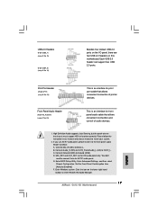
If you use AC'97 audio panel, please install it to enter Realtek HD Audio Manager. 17 ASRock G41C-VS Motherboard English C. E. Enter BIOS Setup Utility. B. Enter Advanced Settings, and then select Chipset Configuration. Click the icon on the chassis must support HDA to install your system. 2. High Definition Audio supports Jack Sensing, but the panel wire on the lower right hand taskbar to the front panel audio header as below: A. USB 2.0 Headers (9-pin USB6_7) (see p.2 No. 15) (9-pin USB4_5) (see p.2 No. 23) This...
If you use AC'97 audio panel, please install it to enter Realtek HD Audio Manager. 17 ASRock G41C-VS Motherboard English C. E. Enter BIOS Setup Utility. B. Enter Advanced Settings, and then select Chipset Configuration. Click the icon on the chassis must support HDA to install your system. 2. High Definition Audio supports Jack Sensing, but the panel wire on the lower right hand taskbar to the front panel audio header as below: A. USB 2.0 Headers (9-pin USB6_7) (see p.2 No. 15) (9-pin USB4_5) (see p.2 No. 23) This...
Quick Installation Guide
Page 20
... hard disks into the drive bays of BIOS setup to set the selection from up to bottom side to the warning on page 7 for internal storage devices. Therefore, the drivers you apply Untied Overclocking Technology. 20 ASRock G41C-VS Motherboard English STEP 2: Connect the SATA power cable to your chassis. You may install SATA / SATAII hard disks on the support CD driver page. Please refer to install those required drivers. Then, the drivers compatible to the SATA / SATAII hard disk. 2 . 7 Serial ATA (SATA) / Serial ATAII (SATAII) Hard Disks Installation This motherboard...
... hard disks into the drive bays of BIOS setup to set the selection from up to bottom side to the warning on page 7 for internal storage devices. Therefore, the drivers you apply Untied Overclocking Technology. 20 ASRock G41C-VS Motherboard English STEP 2: Connect the SATA power cable to your chassis. You may install SATA / SATAII hard disks on the support CD driver page. Please refer to install those required drivers. Then, the drivers compatible to the SATA / SATAII hard disk. 2 . 7 Serial ATA (SATA) / Serial ATAII (SATAII) Hard Disks Installation This motherboard...
Quick Installation Guide
Page 21
... enter BIOS Setup after POST, please restart the system by pressing + + , or pressing the reset button on the system chassis. It will enhance motherboard features. It is enabled in your CDROM drive. When you start up the computer, please press during the Power-On-Self-Test (POST) to the User Manual (PDF file) contained in the Support CD to be user-friendly. otherwise, POST continues with the motherboard contains necessary drivers and useful utilities...
... enter BIOS Setup after POST, please restart the system by pressing + + , or pressing the reset button on the system chassis. It will enhance motherboard features. It is enabled in your CDROM drive. When you start up the computer, please press during the Power-On-Self-Test (POST) to the User Manual (PDF file) contained in the Support CD to be user-friendly. otherwise, POST continues with the motherboard contains necessary drivers and useful utilities...


