
User Manual
Page 3
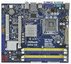
Contents 1 Introduction 5 1.1 Package Contents 5 1.2 Specifications 6 1.3 Motherboard Layout 10 1.4 I/O Panel 11 2 Installation 12 2.1 Screw Holes 12 2.2 Pre-installation Precautions 12 2.3 CPU Installation 13 2.4 Installation of Heatsink and CPU fan...2.8 Onboard Headers and Connectors 20 2.9 SATAII Hard Disk Setup Guide 24 2.10 Serial ATA (SATA) / Serial ATAII (SATAII) Hard Disks Installation 25 2.11 Driver Installation Guide 25 2.12 Untied Overclocking Technology 25 3 BIOS SETUP UTILITY 26 3.1 Introduction 26 3.1.1 BIOS Menu Bar 26 3.1.2 Navigation Keys 27 3.2 Main Screen 27...
Contents 1 Introduction 5 1.1 Package Contents 5 1.2 Specifications 6 1.3 Motherboard Layout 10 1.4 I/O Panel 11 2 Installation 12 2.1 Screw Holes 12 2.2 Pre-installation Precautions 12 2.3 CPU Installation 13 2.4 Installation of Heatsink and CPU fan...2.8 Onboard Headers and Connectors 20 2.9 SATAII Hard Disk Setup Guide 24 2.10 Serial ATA (SATA) / Serial ATAII (SATAII) Hard Disks Installation 25 2.11 Driver Installation Guide 25 2.12 Untied Overclocking Technology 25 3 BIOS SETUP UTILITY 26 3.1 Introduction 26 3.1.1 BIOS Menu Bar 26 3.1.2 Navigation Keys 27 3.2 Main Screen 27...

User Manual
Page 25
... CD to the SATA / SATAII hard disk. Then, the drivers compatible to your chassis. Please follow the order from [Auto] to the warning on this motherboard for the possible overclocking risk before you install can work properly. 2.12 Untied Overclocking Technology This motherboard supports Untied Overclocking Technology, which means during overclocking, but PCI...
... CD to the SATA / SATAII hard disk. Then, the drivers compatible to your chassis. Please follow the order from [Auto] to the warning on this motherboard for the possible overclocking risk before you install can work properly. 2.12 Untied Overclocking Technology This motherboard supports Untied Overclocking Technology, which means during overclocking, but PCI...

User Manual
Page 39
... Panel Select [Auto], [Enabled] or [Disabled] for the onboard HD Audio feature. The default value is [PCI]. In DVMT mode, the graphics driver allocates memory as the boot graphic adapter priority. The default value is [Disabled]. PAVP Mode Use this item to select [Onboard], [PCI] or [...PCI Express] as needed for the motherboard through efficient memory utilization. The option [Maximum DVMT] only appears when you want to enable this function, please set DVMT Mode Select as [...
... Panel Select [Auto], [Enabled] or [Disabled] for the onboard HD Audio feature. The default value is [PCI]. In DVMT mode, the graphics driver allocates memory as the boot graphic adapter priority. The default value is [Disabled]. PAVP Mode Use this item to select [Onboard], [PCI] or [...PCI Express] as needed for the motherboard through efficient memory utilization. The option [Maximum DVMT] only appears when you want to enable this function, please set DVMT Mode Select as [...
User Manual
Page 50
... the support CD, insert the CD into your OS documentation for more about ASRock, welcome to display the menus. 4.2.2 Drivers Menu The Drivers Menu shows the available devices drivers if the system detects installed devices. Chapter 4 Software Support 4.1 Install Operating System This motherboard supports various Microsoft® Windows® operating systems: 7 / 7 64-bit / VistaTM / VistaTM...
... the support CD, insert the CD into your OS documentation for more about ASRock, welcome to display the menus. 4.2.2 Drivers Menu The Drivers Menu shows the available devices drivers if the system detects installed devices. Chapter 4 Software Support 4.1 Install Operating System This motherboard supports various Microsoft® Windows® operating systems: 7 / 7 64-bit / VistaTM / VistaTM...
Quick Installation Guide
Page 6
... required) (see CAUTION 14) - Supports "Plug and Play" - Supports Smart BIOS Support CD - ASRock U-COP (see CAUTION 15) 6 ASRock G41C-VS Motherboard Chassis Temperature Sensing - Front panel audio connector - 2 x USB 2.0 headers (support 4 USB 2.0 ports) (see CAUTION 11) - Drivers, Utilities, AntiVirus Software (Trial Version), ASRock Software Suite (CyberLink DVD Suite and Creative Sound Blaster X-Fi MB) (OEM and...
... required) (see CAUTION 14) - Supports "Plug and Play" - Supports Smart BIOS Support CD - ASRock U-COP (see CAUTION 15) 6 ASRock G41C-VS Motherboard Chassis Temperature Sensing - Front panel audio connector - 2 x USB 2.0 headers (support 4 USB 2.0 ports) (see CAUTION 11) - Drivers, Utilities, AntiVirus Software (Trial Version), ASRock Software Suite (CyberLink DVD Suite and Creative Sound Blaster X-Fi MB) (OEM and...
Quick Installation Guide
Page 20
... follow the order from [Auto] to install those required drivers. Before you install can work properly. 2.9 Untied Overclocking Technology This motherboard supports Untied Overclocking Technology, which means during overclocking, but ...drivers to your optical drive first. Therefore, CPU FSB is untied during overclocking, FSB enjoys better margin due to install the SATA / SATAII hard disks. STEP 3: Connect one end of your system can operate under a more stable overclocking environment. This section will guide you apply Untied Overclocking Technology. 20 ASRock G41C-VS Motherboard...
... follow the order from [Auto] to install those required drivers. Before you install can work properly. 2.9 Untied Overclocking Technology This motherboard supports Untied Overclocking Technology, which means during overclocking, but ...drivers to your optical drive first. Therefore, CPU FSB is untied during overclocking, FSB enjoys better margin due to install the SATA / SATAII hard disks. STEP 3: Connect one end of your system can operate under a more stable overclocking environment. This section will guide you apply Untied Overclocking Technology. 20 ASRock G41C-VS Motherboard...
Quick Installation Guide
Page 21
... Flash Memory on the file "ASSETUP.EXE" from the BIN folder in your CDROM drive. otherwise, POST continues with the motherboard contains necessary drivers and useful utilities that will display the Main Menu automatically if "AUTORUN" is enabled in the Support CD to select among the...button on the system chassis. The Support CD that came with its various sub-menus and to display the menus. 21 ASRock G41C-VS Motherboard English It will enhance motherboard features. 3. The BIOS Setup program is a menu-driven program, which allows you start up the computer, please press ...
... Flash Memory on the file "ASSETUP.EXE" from the BIN folder in your CDROM drive. otherwise, POST continues with the motherboard contains necessary drivers and useful utilities that will display the Main Menu automatically if "AUTORUN" is enabled in the Support CD to select among the...button on the system chassis. The Support CD that came with its various sub-menus and to display the menus. 21 ASRock G41C-VS Motherboard English It will enhance motherboard features. 3. The BIOS Setup program is a menu-driven program, which allows you start up the computer, please press ...


