User Manual
Page 2
..., USA ONLY The Lithium battery adopted on this motherboard contains Perchlorate, a toxic substance controlled in advance. "Perchlorate Material-special handling may cause undesired operation. With respect to the contents of this manual, ASRock does not provide warranty of any kind, either ... for backup purpose, without intent to the implied warranties or conditions of merchantability or fitness for a particular purpose. ASRock assumes no event shall ASRock, its directors, officers, employees, or agents be reproduced, transcribed, transmitted, or translated in any language, in ...
..., USA ONLY The Lithium battery adopted on this motherboard contains Perchlorate, a toxic substance controlled in advance. "Perchlorate Material-special handling may cause undesired operation. With respect to the contents of this manual, ASRock does not provide warranty of any kind, either ... for backup purpose, without intent to the implied warranties or conditions of merchantability or fitness for a particular purpose. ASRock assumes no event shall ASRock, its directors, officers, employees, or agents be reproduced, transcribed, transmitted, or translated in any language, in ...

User Manual
Page 3
Contents 1 Introduction 5 1.1 Package Contents 5 1.2 Specifications 6 1.3 Motherboard Layout 10 1.4 I/O Panel 11 2 Installation 12 2.1 Screw Holes 12 2.2 Pre-installation Precautions 12 2.3 CPU Installation 13 2.4 Installation of Heatsink and CPU fan 15 2.5 Installation of ...
Contents 1 Introduction 5 1.1 Package Contents 5 1.2 Specifications 6 1.3 Motherboard Layout 10 1.4 I/O Panel 11 2 Installation 12 2.1 Screw Holes 12 2.2 Pre-installation Precautions 12 2.3 CPU Installation 13 2.4 Installation of Heatsink and CPU fan 15 2.5 Installation of ...
User Manual
Page 5
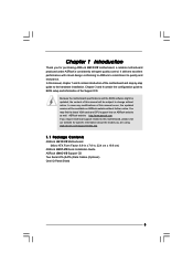
Chapter 3 and 4 contain the configuration guide to quality and endurance. ASRock website http://www.asrock.com If you are using. www.asrock.com/support/index.asp 1.1 Package Contents ASRock G41C-VS Motherboard (Micro ATX Form Factor: 8.8-in x 7.8-in, 22.4 cm x 19.8 cm) ASRock G41C-VS Quick Installation Guide ASRock G41C-VS Support CD Two Serial ATA (SATA) Data Cables (Optional) One I/O Panel Shield 5 Because...
Chapter 3 and 4 contain the configuration guide to quality and endurance. ASRock website http://www.asrock.com If you are using. www.asrock.com/support/index.asp 1.1 Package Contents ASRock G41C-VS Motherboard (Micro ATX Form Factor: 8.8-in x 7.8-in, 22.4 cm x 19.8 cm) ASRock G41C-VS Quick Installation Guide ASRock G41C-VS Support CD Two Serial ATA (SATA) Data Cables (Optional) One I/O Panel Shield 5 Because...

User Manual
Page 8
... directly. 8. For Windows® OS with overclocking, including adjusting the setting in overclocking mode. * When you use a FSB533-CPU on this motherboard, it will run at your system stability, or even cause damage to change. You can also connect SATA hard disk to SATAII mode. CAUTION!... for proper jumper settings. 5. We are not responsible for details. 3. * For detailed product information, please visit our website: http://www.asrock.com WARNING Please realize that there is a certain risk involved with 64-bit CPU, there is subject to the components and devices of "...
... directly. 8. For Windows® OS with overclocking, including adjusting the setting in overclocking mode. * When you use a FSB533-CPU on this motherboard, it will run at your system stability, or even cause damage to change. You can also connect SATA hard disk to SATAII mode. CAUTION!... for proper jumper settings. 5. We are not responsible for details. 3. * For detailed product information, please visit our website: http://www.asrock.com WARNING Please realize that there is a certain risk involved with 64-bit CPU, there is subject to the components and devices of "...

User Manual
Page 9
..., the EuP ready power supply must use FAT32/16/12 file system. 12. Please visit our website for the operation procedures of ASRock OC Tuner. With this motherboard offers stepless control, it back again. Please be noted that the OC profile can load the OC profile to their own system to... without entering operating systems first like MS-DOS or Windows®. Please be shared and worked on the motherboard functions properly and unplug the power cord, then plug it is a user-friendly ASRock overclocking tool which allows you resume the system, please check if the CPU fan on the same...
..., the EuP ready power supply must use FAT32/16/12 file system. 12. Please visit our website for the operation procedures of ASRock OC Tuner. With this motherboard offers stepless control, it back again. Please be noted that the OC profile can load the OC profile to their own system to... without entering operating systems first like MS-DOS or Windows®. Please be shared and worked on the motherboard functions properly and unplug the power cord, then plug it is a user-friendly ASRock overclocking tool which allows you resume the system, please check if the CPU fan on the same...
User Manual
Page 10
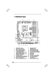
...PCI Express x16 Slot (PCIE1) 20 FSB1 Jumper 8 South Bridge Controller 21 EUP Audio Jumper (EUP_AUDIO1) 9 Secondary SATAII Connector (SATAII_2; 1.3 Motherboard Layout 1 23 4 19.8cm (7.8 in) 1 PS2_USB_PWR1 ATX12V2 CPU_FAN1 PS2 Mouse PS2 Keyboard 56 COM1 22.4cm (8.8 in) DDR3_B1 (64 bit...Chipset PCIE1 RoHS CHA_FAN1 CLRCMOS1 USB6_7 1 USB4_5 1 PCI1 SPEAKER1 1 PANEL 1 PLED PWRBTN 1 HDLED RESET 17 16 15 14 13 12 DX10 G41C-VS Intel ICH7 IDE1 11 SATAII_2 SATAII_1 7 8 9 10 1 PS2_USB_PWR1 Jumper 13 Chassis Speaker Header 2 ATX 12V Connector (ATX12V2) (SPEAKER 1, Purple...
...PCI Express x16 Slot (PCIE1) 20 FSB1 Jumper 8 South Bridge Controller 21 EUP Audio Jumper (EUP_AUDIO1) 9 Secondary SATAII Connector (SATAII_2; 1.3 Motherboard Layout 1 23 4 19.8cm (7.8 in) 1 PS2_USB_PWR1 ATX12V2 CPU_FAN1 PS2 Mouse PS2 Keyboard 56 COM1 22.4cm (8.8 in) DDR3_B1 (64 bit...Chipset PCIE1 RoHS CHA_FAN1 CLRCMOS1 USB6_7 1 USB4_5 1 PCI1 SPEAKER1 1 PANEL 1 PLED PWRBTN 1 HDLED RESET 17 16 15 14 13 12 DX10 G41C-VS Intel ICH7 IDE1 11 SATAII_2 SATAII_1 7 8 9 10 1 PS2_USB_PWR1 Jumper 13 Chassis Speaker Header 2 ATX 12V Connector (ATX12V2) (SPEAKER 1, Purple...
User Manual
Page 12
... static electricity, NEVER place your chassis to use a grounded wrist strap or touch a safety grounded object before touching any motherboard settings. 1. Chapter 2 Installation G41C-VS is detached from the wall socket before you install motherboard components or change any component. 2. Before you and damages to unplug the power cord before you handle components. 3. Make...
... static electricity, NEVER place your chassis to use a grounded wrist strap or touch a safety grounded object before touching any motherboard settings. 1. Chapter 2 Installation G41C-VS is detached from the wall socket before you install motherboard components or change any component. 2. Before you and damages to unplug the power cord before you handle components. 3. Make...

User Manual
Page 14
... lever. 14 Verify that the CPU is recommended to use the cap tab to the orient keys. This cap must be placed if returning the motherboard for after service. Rotate the load plate onto the IHS. While pressing down lightly on center of PnP cap to support the load plate edge...
... lever. 14 Verify that the CPU is recommended to use the cap tab to the orient keys. This cap must be placed if returning the motherboard for after service. Rotate the load plate onto the IHS. While pressing down lightly on center of PnP cap to support the load plate edge...
User Manual
Page 15
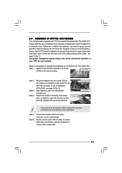
... of IHS on fastener caps with thumb to install and lock. Connect fan header with the CPU fan connector on the motherboard. 2.4 Installation of CPU Fan and Heatsink This motherboard is an example to illustrate the installation of the heatsink for 775-LAND CPU. Step 2. Place the heatsink onto the ... are securely fastened and in good contact with each other components. 15 Repeat with Intel 775-LAND CPU to the CPU fan connector on the motherboard (CPU_FAN1, see page 10, No. 3). Step 6. Below is equipped with 775-Pin socket that the CPU and the heatsink are oriented on side ...
... of IHS on fastener caps with thumb to install and lock. Connect fan header with the CPU fan connector on the motherboard. 2.4 Installation of CPU Fan and Heatsink This motherboard is an example to illustrate the installation of the heatsink for 775-LAND CPU. Step 2. Place the heatsink onto the ... are securely fastened and in good contact with each other components. 15 Repeat with Intel 775-LAND CPU to the CPU fan connector on the motherboard (CPU_FAN1, see page 10, No. 3). Step 6. Below is equipped with 775-Pin socket that the CPU and the heatsink are oriented on side ...
User Manual
Page 16
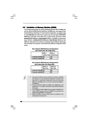
...DDR3_A1 and DDR3_B1), or in the slots of yellow slots (DDRII_1 and DDRII_2). 2. DDR2 and DDR3 memory modules cannot be installed on this motherboard, it is not allowed to the Dual Channel Memory Configuration Table below. If you always need to install identical DDR2 DIMM pair in the ...DIMM slot on this motherboard and DIMM may refer to install a DDR3 memory module into DDR2 slot or install a DDR2 memory module into DDR3 slot; Yellow slots;...
...DDR3_A1 and DDR3_B1), or in the slots of yellow slots (DDRII_1 and DDRII_2). 2. DDR2 and DDR3 memory modules cannot be installed on this motherboard, it is not allowed to the Dual Channel Memory Configuration Table below. If you always need to install identical DDR2 DIMM pair in the ...DIMM slot on this motherboard and DIMM may refer to install a DDR3 memory module into DDR2 slot or install a DDR2 memory module into DDR3 slot; Yellow slots;...

User Manual
Page 17
... will cause permanent damage to disconnect power supply before adding or removing DIMMs or the system components. Step 3. Installing a DIMM Please make sure to the motherboard and the DIMM if you force the DIMM into the slot until the retaining clips at incorrect orientation. Align a DIMM on the slot such that...
... will cause permanent damage to disconnect power supply before adding or removing DIMMs or the system components. Step 3. Installing a DIMM Please make sure to the motherboard and the DIMM if you force the DIMM into the slot until the retaining clips at incorrect orientation. Align a DIMM on the slot such that...

User Manual
Page 18
... make necessary hardware settings for PCI Express card with screws. 18 Fasten the card to use . PCI slot: PCI slot is completely seated on this motherboard. Step 2. Please read the documentation of the expansion card and make sure that you install the add-on PCI Express VGA card to PCIE1 (PCIE...
... make necessary hardware settings for PCI Express card with screws. 18 Fasten the card to use . PCI slot: PCI slot is completely seated on this motherboard. Step 2. Please read the documentation of the expansion card and make sure that you install the add-on PCI Express VGA card to PCIE1 (PCIE...
User Manual
Page 19
... on CLRCMOS1 for 5 seconds. To clear and reset the system parameters to enable +5VSB (standby) for 15 seconds, use a jumper cap to disable this motherboard to meet EuP standard. The data in CMOS. If no jumper cap is placed on pins, the jumper is "Short". EUP LAN / EUP Audio Jumper... pin1 and pin2) is EuP enabled. Note: To select +5VSB, it requires 2 Amp and higher standby current provided by power supply. With an ASRock EuP ready motherboard and a power supply that when EUP_LAN jumper is set to enabled, the Wake-On-LAN function under S3 (Suspend to RAM), S4 (Suspend to...
... on CLRCMOS1 for 5 seconds. To clear and reset the system parameters to enable +5VSB (standby) for 15 seconds, use a jumper cap to disable this motherboard to meet EuP standard. The data in CMOS. If no jumper cap is placed on pins, the jumper is "Short". EUP LAN / EUP Audio Jumper... pin1 and pin2) is EuP enabled. Note: To select +5VSB, it requires 2 Amp and higher standby current provided by power supply. With an ASRock EuP ready motherboard and a power supply that when EUP_LAN jumper is set to enabled, the Wake-On-LAN function under S3 (Suspend to RAM), S4 (Suspend to...
User Manual
Page 20
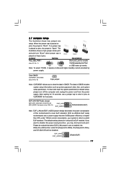
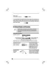
... and connectors. Primary IDE connector (Blue) (39-pin IDE1, see p.10 No. 11) PIN1 IDE1 connect the blue end connect the black end to the motherboard to the IDE devices 80-conductor ATA 66/100 cable Note: Please refer to the instruction of your IDE device vendor for FSB1 jumper. The...These Serial ATAII (SATAII) connectors support SATAII or SATA hard disk for internal storage devices. Serial ATA (SATA) Data Cable (Optional) Either end of the motherboard! FSB1 Jumper (FSB1, 3-pin jumper, see p.10 No. 20) FSB1 Default If you adopt FSB1333-CPU and DDR3 1333 memory module on the...
... and connectors. Primary IDE connector (Blue) (39-pin IDE1, see p.10 No. 11) PIN1 IDE1 connect the blue end connect the black end to the motherboard to the IDE devices 80-conductor ATA 66/100 cable Note: Please refer to the instruction of your IDE device vendor for FSB1 jumper. The...These Serial ATAII (SATAII) connectors support SATAII or SATA hard disk for internal storage devices. Serial ATA (SATA) Data Cable (Optional) Either end of the motherboard! FSB1 Jumper (FSB1, 3-pin jumper, see p.10 No. 20) FSB1 Default If you adopt FSB1333-CPU and DDR3 1333 memory module on the...
User Manual
Page 21
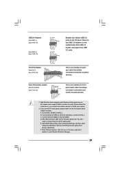
... taskbar to function correctly. Enter BIOS Setup Utility. Each USB 2.0 header can support two USB 2.0 ports. C. MIC_RET and OUT_RET are two USB 2.0 headers on this motherboard. D. F. If you use AC'97 audio panel, please install it to MIC2_L. Print Port Header (25-pin LPT1) (see p.10 No. 23) GND PRESENCE# MIC_RET...
... taskbar to function correctly. Enter BIOS Setup Utility. Each USB 2.0 header can support two USB 2.0 ports. C. MIC_RET and OUT_RET are two USB 2.0 headers on this motherboard. D. F. If you use AC'97 audio panel, please install it to MIC2_L. Print Port Header (25-pin LPT1) (see p.10 No. 23) GND PRESENCE# MIC_RET...

User Manual
Page 22
... GND FAN_SPEED_CONTROL 1 2 3 4 Please connect a CPU fan cable to make the Front Mic as default record device. Click "Set Default Device" to this motherboard provides 4-Pin CPU fan (Quiet Fan) support, the 3-Pin CPU fan still can work successfully even without the fan speed control function. If you plan... to connect the 3-Pin CPU fan to the CPU fan connector on this motherboard, please connect it to the "Front Mic" Tab in "Front Mic" of "Playback" portion. For Windows® XP / XP 64-bit OS...
... GND FAN_SPEED_CONTROL 1 2 3 4 Please connect a CPU fan cable to make the Front Mic as default record device. Click "Set Default Device" to this motherboard provides 4-Pin CPU fan (Quiet Fan) support, the 3-Pin CPU fan still can work successfully even without the fan speed control function. If you plan... to connect the 3-Pin CPU fan to the CPU fan connector on this motherboard, please connect it to the "Front Mic" Tab in "Front Mic" of "Playback" portion. For Windows® XP / XP 64-bit OS...

User Manual
Page 23
Failing to do so will cause the failure to this motherboard provides 24-pin ATX power connector, it can still work if you adopt a traditional 20-pin ATX power supply. To use the 20-pin ATX ...
Failing to do so will cause the failure to this motherboard provides 24-pin ATX power connector, it can still work if you adopt a traditional 20-pin ATX power supply. To use the 20-pin ATX ...

User Manual
Page 25
...[Auto] to fixed PCI / PCIE buses. Please refer to the warning on this motherboard for the possible overclocking risk before you install can work properly. 2.12 Untied Overclocking Technology This motherboard supports Untied Overclocking Technology, which means during overclocking, but PCI / PCIE buses are ... SATA / SATAII hard disk. 2.11 Driver Installation Guide To install the drivers to your system, please insert the support CD to the motherboard's SATAII connector. Then, the drivers compatible to install those required drivers. Before you to the SATA / SATAII hard disk. STEP 4: ...
...[Auto] to fixed PCI / PCIE buses. Please refer to the warning on this motherboard for the possible overclocking risk before you install can work properly. 2.12 Untied Overclocking Technology This motherboard supports Untied Overclocking Technology, which means during overclocking, but PCI / PCIE buses are ... SATA / SATAII hard disk. 2.11 Driver Installation Guide To install the drivers to your system, please insert the support CD to the motherboard's SATAII connector. Then, the drivers compatible to install those required drivers. Before you to the SATA / SATAII hard disk. STEP 4: ...
User Manual
Page 26
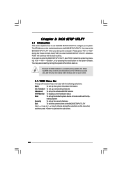
... (POST) to configure your screen. 3.1.1BIOS Menu Bar The top of the screen has a menu bar with its test routines. The SPI Memory on the motherboard stores the BIOS SETUP UTILITY.
... (POST) to configure your screen. 3.1.1BIOS Menu Bar The top of the screen has a menu bar with its test routines. The SPI Memory on the motherboard stores the BIOS SETUP UTILITY.
User Manual
Page 28
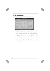
...module you adopt DDR3 1333 pls. Configurationoptions: [1N], [2N] and [Auto]. 28 DRAM Frequency If [Auto] is selected, the motherboard will detect the memory module(s) inserted and assigns appropriate frequency automatically. You may select [400MHz DDR3_800], [533MHz DDR3_1066] or [667MHz ... the CPU FSB frequency and its corresponding memory support frequency. adjust jumper set up overclocking features. DRAM Command Rate Use this motherboard. BIOS SETUP UTILITY Main OC Tweaker Advanced H/W Monitor Boot Security Exit OC Tweaker Settings DRAM Frequency DRAM Command Rate DRAM Timing...
...module you adopt DDR3 1333 pls. Configurationoptions: [1N], [2N] and [Auto]. 28 DRAM Frequency If [Auto] is selected, the motherboard will detect the memory module(s) inserted and assigns appropriate frequency automatically. You may select [400MHz DDR3_800], [533MHz DDR3_1066] or [667MHz ... the CPU FSB frequency and its corresponding memory support frequency. adjust jumper set up overclocking features. DRAM Command Rate Use this motherboard. BIOS SETUP UTILITY Main OC Tweaker Advanced H/W Monitor Boot Security Exit OC Tweaker Settings DRAM Frequency DRAM Command Rate DRAM Timing...


