User Manual
Page 2
CALIFORNIA, USA ONLY The Lithium battery adopted on this motherboard contains Perchlorate, a toxic substance controlled in Perchlorate Best Management Practices (BMP) regulations passed by ASRock. Disclaimer: Specifications and information contained in this manual are used only for identification or explanation and ... accept any interference received, including interference that may appear in this manual. With respect to the contents of this manual, ASRock does not provide warranty of any kind, either expressed or implied, including but not limited to the implied warranties or conditions...
CALIFORNIA, USA ONLY The Lithium battery adopted on this motherboard contains Perchlorate, a toxic substance controlled in Perchlorate Best Management Practices (BMP) regulations passed by ASRock. Disclaimer: Specifications and information contained in this manual are used only for identification or explanation and ... accept any interference received, including interference that may appear in this manual. With respect to the contents of this manual, ASRock does not provide warranty of any kind, either expressed or implied, including but not limited to the implied warranties or conditions...
User Manual
Page 3
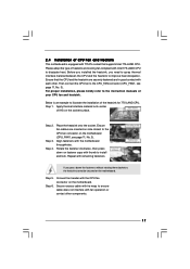
Contents 1 Introduction 5 1.1 Package Contents 5 1.2 Specifications 6 1.3 Motherboard Layout (G41C-GS / G41C-S 11 1.4 I/O Panel (G41C-GS 12 1.5 I/O Panel (G41C-S 13 2 Installation 14 2.1 Screw Holes 14 2.2 Pre-installation Precautions 14 2.3 CPU Installation 15 2.4 Installation of Heatsink and CPU fan 17 2.5 Installation of Memory Modules (DIMM ...
Contents 1 Introduction 5 1.1 Package Contents 5 1.2 Specifications 6 1.3 Motherboard Layout (G41C-GS / G41C-S 11 1.4 I/O Panel (G41C-GS 12 1.5 I/O Panel (G41C-S 13 2 Installation 14 2.1 Screw Holes 14 2.2 Pre-installation Precautions 14 2.3 CPU Installation 15 2.4 Installation of Heatsink and CPU fan 17 2.5 Installation of Memory Modules (DIMM ...
User Manual
Page 5
...on ASRock website as well. ASRock website http://www.asrock.com If you are using. www.asrock.com/support/index.asp 1.1 Package Contents ASRock G41C-GS / G41C-S Motherboard (Micro ATX Form Factor: 9.6-in x 7.8-in, 24.4 cm x 19.8 cm) ASRock G41C-GS / G41C-S Quick Installation Guide ASRock G41C-GS / G41C-S ... information about the model you require technical support related to this motherboard, please visit our website for purchasing ASRock G41C-GS / G41C-S motherboard, a reliable motherboard produced under ASRock's consistently stringent quality control. You may find the latest VGA cards...
...on ASRock website as well. ASRock website http://www.asrock.com If you are using. www.asrock.com/support/index.asp 1.1 Package Contents ASRock G41C-GS / G41C-S Motherboard (Micro ATX Form Factor: 9.6-in x 7.8-in, 24.4 cm x 19.8 cm) ASRock G41C-GS / G41C-S Quick Installation Guide ASRock G41C-GS / G41C-S ... information about the model you require technical support related to this motherboard, please visit our website for purchasing ASRock G41C-GS / G41C-S motherboard, a reliable motherboard produced under ASRock's consistently stringent quality control. You may find the latest VGA cards...

User Manual
Page 8
...maximum shared memory size is subject to read "Untied Overclocking Technology" on this motherboard, you implement Dual Channel Memory Technology, make sure to change. This motherboard supports Dual Channel Memory Technology. Before you need to the components and devices... information, please visit our website: http://www.asrock.com WARNING Please realize that there is no such limitation. 6. It should be less than 4GB for the reservation for the latest information. 7. This motherboard supports Untied Overclocking Technology. Certifications - Before installing...
...maximum shared memory size is subject to read "Untied Overclocking Technology" on this motherboard, you implement Dual Channel Memory Technology, make sure to change. This motherboard supports Dual Channel Memory Technology. Before you need to the components and devices... information, please visit our website: http://www.asrock.com WARNING Please realize that there is no such limitation. 6. It should be less than 4GB for the reservation for the latest information. 7. This motherboard supports Untied Overclocking Technology. Certifications - Before installing...
User Manual
Page 9
...DNA, you can only be noticed that the USB flash drive or hard drive must use FAT32/16/12 file system. 12. Although this motherboard offers stepless control, it is a BIOS flash utility embedded in a few clicks without preparing an additional floppy diskette or other than the ... system, please check if the CPU fan on the same motherboard. 13. Before you to perform over-clocking. Please be shared and worked on the motherboard functions properly and unplug the power cord, then plug it is a user-friendly ASRock overclocking tool which allows you install the PC system. 9 ...
...DNA, you can only be noticed that the USB flash drive or hard drive must use FAT32/16/12 file system. 12. Although this motherboard offers stepless control, it is a BIOS flash utility embedded in a few clicks without preparing an additional floppy diskette or other than the ... system, please check if the CPU fan on the same motherboard. 13. Before you to perform over-clocking. Please be shared and worked on the motherboard functions properly and unplug the power cord, then plug it is a user-friendly ASRock overclocking tool which allows you install the PC system. 9 ...

User Manual
Page 10
... system shall be under 100 mA current consumption. 15. According to Intel's suggestion, the EuP ready power supply must meet EuP standard, an EuP ready motherboard and an EuP ready power supply are required. According to define the power consumption for the completed system. For EuP ready power supply selection, we...
... system shall be under 100 mA current consumption. 15. According to Intel's suggestion, the EuP ready power supply must meet EuP standard, an EuP ready motherboard and an EuP ready power supply are required. According to define the power consumption for the completed system. For EuP ready power supply selection, we...
User Manual
Page 11
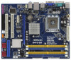
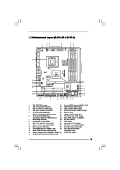
... (EUP_LAN1) 12 Third SATAII Connector (SATAII_3; Red) (HD_AUDIO1, Lime) 14 Chassis Speaker Header (SPEAKER 1, Purple) 30 775-Pin CPU Socket 15 Secondary SATAII Connector (SATAII_2; 1.3 Motherboard Layout (G41C-GS / G41C-S) 1 23 4 19.8cm (7.8 in) 1 PS2_USB_PWR1 ATX12V2 CPU_FAN1 56 PS2 Mouse PS2 Keyboard COM1 24.4cm (9.6 in) DDR3_B1 (64 bit, 240-FpinSBmo8d0ul0e) DDRII_2 (64 bit...
... (EUP_LAN1) 12 Third SATAII Connector (SATAII_3; Red) (HD_AUDIO1, Lime) 14 Chassis Speaker Header (SPEAKER 1, Purple) 30 775-Pin CPU Socket 15 Secondary SATAII Connector (SATAII_2; 1.3 Motherboard Layout (G41C-GS / G41C-S) 1 23 4 19.8cm (7.8 in) 1 PS2_USB_PWR1 ATX12V2 CPU_FAN1 56 PS2 Mouse PS2 Keyboard COM1 24.4cm (9.6 in) DDR3_B1 (64 bit, 240-FpinSBmo8d0ul0e) DDRII_2 (64 bit...
User Manual
Page 14
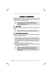
... screws into it on the carpet or the like. Hold components by circles to secure the motherboard to the chassis. Failure to unplug the power cord before you install motherboard components or change any component. 2. Chapter 2 Installation G41C-GS / G41C-S is detached from the wall socket before you handle components. 3. Make sure to do not...
... screws into it on the carpet or the like. Hold components by circles to secure the motherboard to the chassis. Failure to unplug the power cord before you install motherboard components or change any component. 2. Chapter 2 Installation G41C-GS / G41C-S is detached from the wall socket before you handle components. 3. Make sure to do not...
User Manual
Page 16
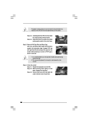
... motion. Step 2-4. Verify that the CPU is recommended to use the cap tab to the orient keys. This cap must be placed if returning the motherboard for after service. Rotate the load plate onto the IHS. Step 4. Step 4-2. Step 3. Step 4-3. For proper inserting, please ensure to match the two orientation key...
... motion. Step 2-4. Verify that the CPU is recommended to use the cap tab to the orient keys. This cap must be placed if returning the motherboard for after service. Rotate the load plate onto the IHS. Step 4. Step 4-2. Step 3. Step 4-3. For proper inserting, please ensure to match the two orientation key...
User Manual
Page 17
... instruction manuals of heatsink and cooling fan compliant with Intel 775-LAND CPU to illustrate the installation of CPU Fan and Heatsink This motherboard is an example to dissipate heat. Place the heatsink onto the socket. Connect fan header with 775-Pin socket that the CPU...fan and heatsink. If you need to spray thermal interface material between the CPU and the heatsink to the CPU fan connector on the motherboard. Step 5. Align fasteners with remaining fasteners. Rotate the fastener clockwise, then press down the fasteners without rotating them clockwise, the heatsink ...
... instruction manuals of heatsink and cooling fan compliant with Intel 775-LAND CPU to illustrate the installation of CPU Fan and Heatsink This motherboard is an example to dissipate heat. Place the heatsink onto the socket. Connect fan header with 775-Pin socket that the CPU...fan and heatsink. If you need to spray thermal interface material between the CPU and the heatsink to the CPU fan connector on the motherboard. Step 5. Align fasteners with remaining fasteners. Rotate the fastener clockwise, then press down the fasteners without rotating them clockwise, the heatsink ...

User Manual
Page 18
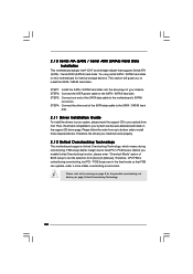
... Channel Memory Technology can be activated. see p.11 No.5), or identical DDR3 DIMM pair in Dual Channel (DDRII_1 and DDRII_2; otherwise, this motherboard and DIMM may refer to install identical DDR2 DIMM pair in Dual Channel (DDR3_A1 and DDR3_B1; If only one memory module is installed in the...Rate 3) DIMM slots, and supports Dual Channel Memory Technology. DDR2 and DDR3 memory modules cannot be damaged. 4. You may be installed on this motherboard, it is not allowed to install identical (the same brand, speed, size and chip-type) DDR2/DDR3 DIMM pair in the DIMM slot on ...
... Channel Memory Technology can be activated. see p.11 No.5), or identical DDR3 DIMM pair in Dual Channel (DDRII_1 and DDRII_2; otherwise, this motherboard and DIMM may refer to install identical DDR2 DIMM pair in Dual Channel (DDR3_A1 and DDR3_B1; If only one memory module is installed in the...Rate 3) DIMM slots, and supports Dual Channel Memory Technology. DDR2 and DDR3 memory modules cannot be damaged. 4. You may be installed on this motherboard, it is not allowed to install identical (the same brand, speed, size and chip-type) DDR2/DDR3 DIMM pair in the DIMM slot on ...

User Manual
Page 19
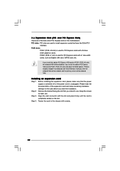
Installing a DIMM Please make sure to the motherboard and the DIMM if you force the DIMM into the slot until the retaining clips at incorrect orientation. Step 1. Firmly insert the DIMM into the ...
Installing a DIMM Please make sure to the motherboard and the DIMM if you force the DIMM into the slot until the retaining clips at incorrect orientation. Step 1. Firmly insert the DIMM into the ...
User Manual
Page 20
... graphics cards. Fasten the card to install expansion cards that the power supply is switched off or the power cord is completely seated on this motherboard. Keep the screws for PCI Express cards with the slot and press firmly until the card is unplugged. 2.6 Expansion Slots (PCI and PCI Express Slots...
... graphics cards. Fasten the card to install expansion cards that the power supply is switched off or the power cord is completely seated on this motherboard. Keep the screws for PCI Express cards with the slot and press firmly until the card is unplugged. 2.6 Expansion Slots (PCI and PCI Express Slots...

User Manual
Page 21
.... EUP_LAN1 EUP_AUDIO1 (Disable EuP) 21 If no jumper cap is placed on pins, the jumper is EuP enabled. If you want to disable this motherboard to submit EuP standard. Please be disabled. 2.7 Jumpers Setup The illustration shows how jumpers are "Short" when jumper cap is placed on these 2... pins. Note: To select +5VSB, it requires 2 Amp and higher standby current provided by power supply. With an ASRock EuP ready motherboard and a power supply that when EUP_LAN jumper is set to enabled, the Wake-On-LAN function under S3 (Suspend to RAM), S4 (Suspend...
.... EUP_LAN1 EUP_AUDIO1 (Disable EuP) 21 If no jumper cap is placed on pins, the jumper is EuP enabled. If you want to disable this motherboard to submit EuP standard. Please be disabled. 2.7 Jumpers Setup The illustration shows how jumpers are "Short" when jumper cap is placed on these 2... pins. Note: To select +5VSB, it requires 2 Amp and higher standby current provided by power supply. With an ASRock EuP ready motherboard and a power supply that when EUP_LAN jumper is set to enabled, the Wake-On-LAN function under S3 (Suspend to RAM), S4 (Suspend...
User Manual
Page 22
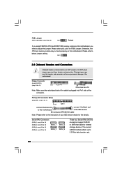
...for internal storage devices. Otherwise, the CPU and memory module may not work properly on this motherboard. Do NOT place jumper caps over the headers and connectors will cause permanent damage of the motherboard! The current SATAII interface allows up to below jumper setting. Primary IDE connector (Blue) (...39-pin IDE1, see p.11 No. 11) PIN1 IDE1 connect the blue end connect the black end to the motherboard to the IDE devices 80-conductor ATA 66/100 cable Note: Please refer to the instruction of the connector. FSB1 Jumper (FSB1, 3-pin jumper...
...for internal storage devices. Otherwise, the CPU and memory module may not work properly on this motherboard. Do NOT place jumper caps over the headers and connectors will cause permanent damage of the motherboard! The current SATAII interface allows up to below jumper setting. Primary IDE connector (Blue) (...39-pin IDE1, see p.11 No. 11) PIN1 IDE1 connect the blue end connect the black end to the motherboard to the IDE devices 80-conductor ATA 66/100 cable Note: Please refer to the instruction of the connector. FSB1 Jumper (FSB1, 3-pin jumper...
User Manual
Page 23
... connected to function correctly. Please follow the instruction in our manual and chassis manual to MIC2_L. MIC_RET and OUT_RET are two USB 2.0 headers on the motherboard. Enter Advanced Settings, and then select Chipset Configuration. Connect Audio_R (RIN) to OUT2_R and Audio_L (LIN) to Ground (GND). Connect Ground (GND)..., but the panel wire on the chassis must support HDA to the SATA / SATAII hard disk or the SATAII connector on this motherboard. D. If you use AC'97 audio panel, please install it to connect them for front panel audio cable that allows convenient connection...
... connected to function correctly. Please follow the instruction in our manual and chassis manual to MIC2_L. MIC_RET and OUT_RET are two USB 2.0 headers on the motherboard. Enter Advanced Settings, and then select Chipset Configuration. Connect Audio_R (RIN) to OUT2_R and Audio_L (LIN) to Ground (GND). Connect Ground (GND)..., but the panel wire on the chassis must support HDA to the SATA / SATAII hard disk or the SATAII connector on this motherboard. D. If you use AC'97 audio panel, please install it to connect them for front panel audio cable that allows convenient connection...
User Manual
Page 24
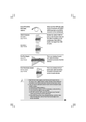
Though this motherboard provides 4-Pin CPU fan (Quiet Fan) support, the 3-Pin CPU fan still can provides sufficient power. CPU...that it can work if you plan to connect the 3-Pin CPU fan to the CPU fan connector on this motherboard, please connect it can still work successfully even without the fan speed control function. Please connect the chassis speaker ... PWR_FAN1) (see p.11 No. 4) 12 Please connect an ATX power 13 supply to this connector. 1 Though this motherboard provides 24-pin ATX power connector, it to the ground pin. If you adopt a traditional 20-pin ATX power supply.
Though this motherboard provides 4-Pin CPU fan (Quiet Fan) support, the 3-Pin CPU fan still can provides sufficient power. CPU...that it can work if you plan to connect the 3-Pin CPU fan to the CPU fan connector on this motherboard, please connect it can still work successfully even without the fan speed control function. Please connect the chassis speaker ... PWR_FAN1) (see p.11 No. 4) 12 Please connect an ATX power 13 supply to this connector. 1 Though this motherboard provides 24-pin ATX power connector, it to the ground pin. If you adopt a traditional 20-pin ATX power supply.
User Manual
Page 26
...Please follow the order from [Auto] to install those required drivers. Before you install can work properly. 2 . 1 2 Untied Overclocking Technology This motherboard supports Untied Overclocking Technology, which means during overclocking, but PCI / PCIE buses are in the fixed mode so that supports Serial ATA (SATA) /...hard disks on the support CD driver page. STEP 3: Connect one end of your system can be auto-detected and listed on this motherboard for the possible overclocking risk before you to the warning on page 8 for internal storage devices. Therefore, CPU FSB is untied during...
...Please follow the order from [Auto] to install those required drivers. Before you install can work properly. 2 . 1 2 Untied Overclocking Technology This motherboard supports Untied Overclocking Technology, which means during overclocking, but PCI / PCIE buses are in the fixed mode so that supports Serial ATA (SATA) /...hard disks on the support CD driver page. STEP 3: Connect one end of your system can be auto-detected and listed on this motherboard for the possible overclocking risk before you to the warning on page 8 for internal storage devices. Therefore, CPU FSB is untied during...
User Manual
Page 27
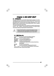
... press to enter the BIOS SETUP UTILITY after POST, restart the system by pressing + + , or by turning the system off and then back on the motherboard stores the BIOS SETUP UTILITY. Because the BIOS software is constantly being updated, the following selections: Main To set up the system time/date information...
... press to enter the BIOS SETUP UTILITY after POST, restart the system by pressing + + , or by turning the system off and then back on the motherboard stores the BIOS SETUP UTILITY. Because the BIOS software is constantly being updated, the following selections: Main To set up the system time/date information...
User Manual
Page 30
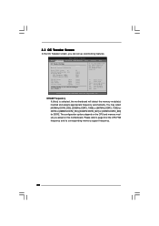
... = 2-3 DRAM Voltage NB Voltage VTT Voltage GTLRef Voltage 1.96V 1.23V 1.20V 0.63Vtt [Auto] [Auto] [Auto] [Auto] Would you adopt on this motherboard. DRAM Frequency If [Auto] is selected, the motherboard will detect the memory module(s) inserted and assigns appropriate frequency automatically. Please refer to Sub Screen F1 General Help F9 Load Defaults...
... = 2-3 DRAM Voltage NB Voltage VTT Voltage GTLRef Voltage 1.96V 1.23V 1.20V 0.63Vtt [Auto] [Auto] [Auto] [Auto] Would you adopt on this motherboard. DRAM Frequency If [Auto] is selected, the motherboard will detect the memory module(s) inserted and assigns appropriate frequency automatically. Please refer to Sub Screen F1 General Help F9 Load Defaults...


