User Manual
Page 11
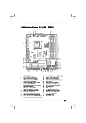
...Dual Channel: DDR3_A1, DDR3_B1; Blue) 23 Clear CMOS Jumper (CLRCMOS1) 7 North Bridge Controller 24 PCI Slots (PCI1-2) 8 PCI Express x16 Slot (PCIE1) 25 FSB1 Jumper 9 Power Fan Connector (PWR_FAN1) 26 PCI Express x1... Slot (PCIE2) 10 Chassis Fan Connector (CHA_FAN1) 27 EUP Audio Jumper (EUP_AUDIO1) 11 IDE1 Connector (IDE1, Blue) 28 EUP LAN Jumper (EUP_LAN1) 12 Third SATAII Connector (SATAII_3; Red) 29 Front Panel Audio Header 13 Fourth SATAII Connector (SATAII_4; Red) 11 1.3 Motherboard Layout (G41C-GS / G41C...
...Dual Channel: DDR3_A1, DDR3_B1; Blue) 23 Clear CMOS Jumper (CLRCMOS1) 7 North Bridge Controller 24 PCI Slots (PCI1-2) 8 PCI Express x16 Slot (PCIE1) 25 FSB1 Jumper 9 Power Fan Connector (PWR_FAN1) 26 PCI Express x1... Slot (PCIE2) 10 Chassis Fan Connector (CHA_FAN1) 27 EUP Audio Jumper (EUP_AUDIO1) 11 IDE1 Connector (IDE1, Blue) 28 EUP LAN Jumper (EUP_LAN1) 12 Third SATAII Connector (SATAII_3; Red) 29 Front Panel Audio Header 13 Fourth SATAII Connector (SATAII_4; Red) 11 1.3 Motherboard Layout (G41C-GS / G41C...
User Manual
Page 22
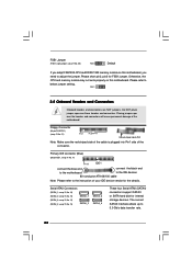
... Connector (33-pin FLOPPY1) (see p.11 No. 21) Pin1 FLOPPY1 the red-striped side to adjust the jumper. FSB1 Jumper (FSB1, 3-pin jumper, see p.11 No. 25) FSB1 Default If you adopt FSB1333-CPU and DDR3 1333 memory module on this motherboard, you need to Pin1 Note: Make sure the red-striped ...side of the cable is plugged into Pin1 side of your IDE device vendor for FSB1 jumper. Please short pin2, pin3 for the details. Otherwise, the CPU and memory module may not work properly on this motherboard. The current SATAII interface...
... Connector (33-pin FLOPPY1) (see p.11 No. 21) Pin1 FLOPPY1 the red-striped side to adjust the jumper. FSB1 Jumper (FSB1, 3-pin jumper, see p.11 No. 25) FSB1 Default If you adopt FSB1333-CPU and DDR3 1333 memory module on this motherboard, you need to Pin1 Note: Make sure the red-striped ...side of the cable is plugged into Pin1 side of your IDE device vendor for FSB1 jumper. Please short pin2, pin3 for the details. Otherwise, the CPU and memory module may not work properly on this motherboard. The current SATAII interface...
User Manual
Page 30
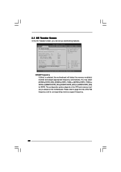
...MHz) [Auto] [8] [Auto] [Auto] [333] [100] If you adopt on the CPU and memory module you adopt DDR3 1333 pls. adjust jumper set up overclocking features. BIOS SETUP UTILITY Main OC Tweaker Advanced H/W Monitor Boot Security Exit OC Tweaker Settings DRAM Frequency DRAM Timing Configuration Ratio CMOS... depend on this motherboard. 3.3 OC Tweaker Screen In the OC Tweaker screen, you like to save current setting as user defaults ? For FSB1333 CPU: FSB1 = 2-3 DRAM Voltage NB Voltage VTT Voltage GTLRef Voltage 1.96V 1.23V 1.20V 0.63Vtt [Auto] [Auto] [Auto] [Auto] Would you can set...
...MHz) [Auto] [8] [Auto] [Auto] [333] [100] If you adopt on the CPU and memory module you adopt DDR3 1333 pls. adjust jumper set up overclocking features. BIOS SETUP UTILITY Main OC Tweaker Advanced H/W Monitor Boot Security Exit OC Tweaker Settings DRAM Frequency DRAM Timing Configuration Ratio CMOS... depend on this motherboard. 3.3 OC Tweaker Screen In the OC Tweaker screen, you like to save current setting as user defaults ? For FSB1333 CPU: FSB1 = 2-3 DRAM Voltage NB Voltage VTT Voltage GTLRef Voltage 1.96V 1.23V 1.20V 0.63Vtt [Auto] [Auto] [Auto] [Auto] Would you can set...
Quick Installation Guide
Page 2
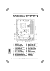
Motherboard Layout (G41C-GS / G41C-S) English 1 PS2_USB_PWR1 Jumper 16 Primary SATAII Connector (SATAII_1; Red) 2 ASRock G41C-GS / G41C-S Motherboard Blue) 23 Clear CMOS Jumper (CLRCMOS1) 7 North Bridge Controller 24 PCI Slots (PCI1-2) 8 PCI Express x16 Slot (PCIE1) 25 FSB1 Jumper 9 Power Fan Connector (PWR_FAN1) 26 PCI Express x1 Slot (PCIE2) 10 Chassis Fan Connector (CHA_FAN1) 27 EUP Audio Jumper (EUP_AUDIO1) 11 IDE1 Connector...
Motherboard Layout (G41C-GS / G41C-S) English 1 PS2_USB_PWR1 Jumper 16 Primary SATAII Connector (SATAII_1; Red) 2 ASRock G41C-GS / G41C-S Motherboard Blue) 23 Clear CMOS Jumper (CLRCMOS1) 7 North Bridge Controller 24 PCI Slots (PCI1-2) 8 PCI Express x16 Slot (PCIE1) 25 FSB1 Jumper 9 Power Fan Connector (PWR_FAN1) 26 PCI Express x1 Slot (PCIE2) 10 Chassis Fan Connector (CHA_FAN1) 27 EUP Audio Jumper (EUP_AUDIO1) 11 IDE1 Connector...
Quick Installation Guide
Page 18
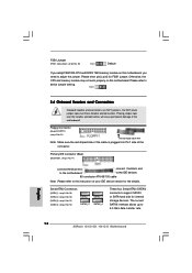
.... Please short pin2, pin3 for internal storage devices. Please refer to 3.0 Gb/s data transfer rate. 18 ASRock G41C-GS / G41C-S Motherboard English Do NOT place jumper caps over the headers and connectors will cause permanent damage of your IDE device vendor for the details. The... properly on this motherboard, you adopt FSB1333-CPU and DDR3 1333 memory module on this motherboard. FSB1 Jumper (FSB1, 3-pin jumper, see p.2 No. 25) Default If you need to adjust the jumper. Floppy Connector (33-pin FLOPPY1) (see p.2, No. 13) SATAII_1 SATAII_2 SATAII_3 SATAII_4 These ...
.... Please short pin2, pin3 for internal storage devices. Please refer to 3.0 Gb/s data transfer rate. 18 ASRock G41C-GS / G41C-S Motherboard English Do NOT place jumper caps over the headers and connectors will cause permanent damage of your IDE device vendor for the details. The... properly on this motherboard, you adopt FSB1333-CPU and DDR3 1333 memory module on this motherboard. FSB1 Jumper (FSB1, 3-pin jumper, see p.2 No. 25) Default If you need to adjust the jumper. Floppy Connector (33-pin FLOPPY1) (see p.2, No. 13) SATAII_1 SATAII_2 SATAII_3 SATAII_4 These ...
