User Manual
Page 3
...(SATA) / Serial ATAII (SATAII) Hard Disks Installation 26 2.11 Driver Installation Guide 26 2.12 Untied Overclocking Technology 26 3 BIOS SETUP UTILITY 27 3.1 Introduction 27 3.1.1 BIOS Menu Bar 27 3.1.2 Navigation Keys 28 3.2 Main Screen 28 3.3 OC Tweaker Screen 30 3.4 Advanced Screen 34 3.4.1 CPU Configuration 35 3.4.2 Chipset Configuration 37 3.4.3 ACPI Configuration 42 3.4.4 Storage Configuration 43 3.4.5 PCIPnP Configuration 45 3.4.6 Floppy Configuration 46 3.4.7 Super IO Configuration 47 3.4.8 USB Configuration 48 3.5 Hardware Health Event Monitoring Screen 49 3.6 Boot...
...(SATA) / Serial ATAII (SATAII) Hard Disks Installation 26 2.11 Driver Installation Guide 26 2.12 Untied Overclocking Technology 26 3 BIOS SETUP UTILITY 27 3.1 Introduction 27 3.1.1 BIOS Menu Bar 27 3.1.2 Navigation Keys 28 3.2 Main Screen 28 3.3 OC Tweaker Screen 30 3.4 Advanced Screen 34 3.4.1 CPU Configuration 35 3.4.2 Chipset Configuration 37 3.4.3 ACPI Configuration 42 3.4.4 Storage Configuration 43 3.4.5 PCIPnP Configuration 45 3.4.6 Floppy Configuration 46 3.4.7 Super IO Configuration 47 3.4.8 USB Configuration 48 3.5 Hardware Health Event Monitoring Screen 49 3.6 Boot...
User Manual
Page 9
... grease between the CPU and the heatsink when you to save your OC settings as yours! OC DNA, an exclusive utility developed by hardware monitor function and overclock your overclocking record under Windows® environment. Power Management for the user to surveil your BIOS only in Flash ROM. ASRock website: http://www.asrock.com 11. Although this motherboard offers stepless control, it is a revolutionary technology that delivers unparalleled...
... grease between the CPU and the heatsink when you to save your OC settings as yours! OC DNA, an exclusive utility developed by hardware monitor function and overclock your overclocking record under Windows® environment. Power Management for the user to surveil your BIOS only in Flash ROM. ASRock website: http://www.asrock.com 11. Although this motherboard offers stepless control, it is a revolutionary technology that delivers unparalleled...
User Manual
Page 11
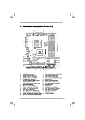
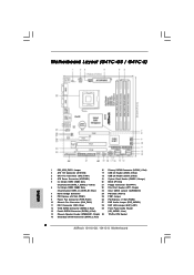
...) 26 PCI Express x1 Slot (PCIE2) 10 Chassis Fan Connector (CHA_FAN1) 27 EUP Audio Jumper (EUP_AUDIO1) 11 IDE1 Connector (IDE1, Blue) 28 EUP LAN Jumper (EUP_LAN1) 12 Third SATAII Connector (SATAII_3; Red) 2 ATX 12V Connector (ATX12V2) 17 USB 2.0 Header (USB6_7, Blue) 3 CPU Fan Connector (CPU_FAN1) 18 USB 2.0 Header (USB4_5, Blue) 4 ATX Power Connector (ATXPWR1) 19 System Panel Header (PANEL1, Orange) 5 2 x 240-pin DDR2 DIMM Slots 20 BIOS SPI Chip (Dual Channel: DDRII_1, DDRII_2; Red) (HD_AUDIO1, Lime) 14 Chassis Speaker Header (SPEAKER 1, Purple) 30 775-Pin CPU Socket 15...
...) 26 PCI Express x1 Slot (PCIE2) 10 Chassis Fan Connector (CHA_FAN1) 27 EUP Audio Jumper (EUP_AUDIO1) 11 IDE1 Connector (IDE1, Blue) 28 EUP LAN Jumper (EUP_LAN1) 12 Third SATAII Connector (SATAII_3; Red) 2 ATX 12V Connector (ATX12V2) 17 USB 2.0 Header (USB6_7, Blue) 3 CPU Fan Connector (CPU_FAN1) 18 USB 2.0 Header (USB4_5, Blue) 4 ATX Power Connector (ATXPWR1) 19 System Panel Header (PANEL1, Orange) 5 2 x 240-pin DDR2 DIMM Slots 20 BIOS SPI Chip (Dual Channel: DDRII_1, DDRII_2; Red) (HD_AUDIO1, Lime) 14 Chassis Speaker Header (SPEAKER 1, Purple) 30 775-Pin CPU Socket 15...
User Manual
Page 23
... Port Header (25-pin LPT1) (see p.11 No. 29) GND PRESENCE# MIC_RET OUT_RET 1 OUT2_L J_SENSE OUT2_R MIC2_R MIC2_L This is an interface for front panel audio cable that allows convenient connection of audio devices. 1. Connect Audio_R (RIN) to OUT2_R and Audio_L (LIN) to the SATA / SATAII hard disk or the SATAII connector on this motherboard. Connect Ground (GND) to [Enabled]. 23 Set the Front Panel Control option from [Auto] to Ground (GND). B. Enter BIOS Setup Utility...
... Port Header (25-pin LPT1) (see p.11 No. 29) GND PRESENCE# MIC_RET OUT_RET 1 OUT2_L J_SENSE OUT2_R MIC2_R MIC2_L This is an interface for front panel audio cable that allows convenient connection of audio devices. 1. Connect Audio_R (RIN) to OUT2_R and Audio_L (LIN) to the SATA / SATAII hard disk or the SATAII connector on this motherboard. Connect Ground (GND) to [Enabled]. 23 Set the Front Panel Control option from [Auto] to Ground (GND). B. Enter BIOS Setup Utility...
User Manual
Page 25
...://www.hitachigst.com/hdd/support/download.htm The above examples are just for changing various ATA features. Some default setting of different vendors, the jumper pin setting methods may not be enabled. otherwise, your SATAII hard disk may not be enabled. On the other hand, if you want to enable SATAII 3.0Gb/s, please remove the jumpers from pin 3 and pin 4. For different SATAII hard disk products of SATAII hard disks may fail...
...://www.hitachigst.com/hdd/support/download.htm The above examples are just for changing various ATA features. Some default setting of different vendors, the jumper pin setting methods may not be enabled. otherwise, your SATAII hard disk may not be enabled. On the other hand, if you want to enable SATAII 3.0Gb/s, please remove the jumpers from pin 3 and pin 4. For different SATAII hard disk products of SATAII hard disks may fail...
User Manual
Page 26
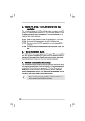
...of BIOS setup to set the selection from up to bottom side to install the SATA / SATAII hard disks. Then, the drivers compatible to your system can work properly. 2 . 1 2 Untied Overclocking Technology This motherboard supports Untied Overclocking Technology, which means during overclocking, but PCI / PCIE buses are in the fixed mode so that supports Serial ATA (SATA) / Serial ATAII (SATAII) hard disks. Therefore, the drivers you enable Untied Overclocking function, please enter "Overclock Mode" option of the SATA data cable to the SATA / SATAII hard disk. 2.11 Driver Installation Guide...
...of BIOS setup to set the selection from up to bottom side to install the SATA / SATAII hard disks. Then, the drivers compatible to your system can work properly. 2 . 1 2 Untied Overclocking Technology This motherboard supports Untied Overclocking Technology, which means during overclocking, but PCI / PCIE buses are in the fixed mode so that supports Serial ATA (SATA) / Serial ATAII (SATAII) hard disks. Therefore, the drivers you enable Untied Overclocking function, please enter "Overclock Mode" option of the SATA data cable to the SATA / SATAII hard disk. 2.11 Driver Installation Guide...
User Manual
Page 32
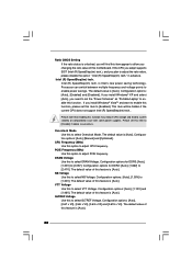
... power supplies. Overclock Mode Use this function may reduce CPU voltage and lead to select Overclock Mode. Intel (R) SpeedStep(tm) tech. If the CPU you adopt supports EIST (Intel (R) SpeedStep(tm) tech.), and you install Windows® VistaTM and want to enable this function, please set this option to [Enabled]. If you plan to select DRAM Voltage. The default value is [Auto]. PCIE Frequency (MHz) Use this item to adjust PCIE frequency. DRAM Voltage Use this feature is [Auto]. The default...
... power supplies. Overclock Mode Use this function may reduce CPU voltage and lead to select Overclock Mode. Intel (R) SpeedStep(tm) tech. If the CPU you adopt supports EIST (Intel (R) SpeedStep(tm) tech.), and you install Windows® VistaTM and want to enable this function, please set this option to [Enabled]. If you plan to select DRAM Voltage. The default value is [Auto]. PCIE Frequency (MHz) Use this item to adjust PCIE frequency. DRAM Voltage Use this feature is [Auto]. The default...
User Manual
Page 35
.... Intel (R) Virtualization tech. in advance. 3.4.1 CPU Configuration BIOS SETUP UTILITY Advanced CPU Configuration Overclock Mode CPU Frequency (MHz) PCIE Frequency (MHz) Boot Failure Guard Spread Spectrum Ratio CMOS Setting 8 Enhanced Halt State Intel (R) Virtualization tech. CPU Thermal Throttling No-Execute Memory Protection Intel (R) SpeedStep (tm) tech. PCIE Frequency (MHz) Use this to [Enabled], a VMM (Virtual Machine Architecture) can utilize the additional hardware capabilities provided by Vanderpool Technology. Configuration options: [Auto], [Manual] and [Optimized...
.... Intel (R) Virtualization tech. in advance. 3.4.1 CPU Configuration BIOS SETUP UTILITY Advanced CPU Configuration Overclock Mode CPU Frequency (MHz) PCIE Frequency (MHz) Boot Failure Guard Spread Spectrum Ratio CMOS Setting 8 Enhanced Halt State Intel (R) Virtualization tech. CPU Thermal Throttling No-Execute Memory Protection Intel (R) SpeedStep (tm) tech. PCIE Frequency (MHz) Use this to [Enabled], a VMM (Virtual Machine Architecture) can utilize the additional hardware capabilities provided by Vanderpool Technology. Configuration options: [Auto], [Manual] and [Optimized...
User Manual
Page 41
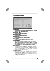
... because the driver will not be disabled when PCI Sound Card is [Auto]. Front Panel Select [Auto], [Enabled] or [Disabled] for running graphics applications and is hardware-based 128-bit AES decryption. Configuration options: [Enabled] and [Disabled]. Configuration options: [Enabled] and [Disabled]. The default value is plugged. PAVP Mode Use this item to adjust PAVP mode. DVMT Mode Select Use this memory with 1024MB or above. Flex Mode Operation This allows you to adjust DVMT mode. Onboard HD Audio Select [Auto], [Enabled] or [Disabled] for...
... because the driver will not be disabled when PCI Sound Card is [Auto]. Front Panel Select [Auto], [Enabled] or [Disabled] for running graphics applications and is hardware-based 128-bit AES decryption. Configuration options: [Enabled] and [Disabled]. Configuration options: [Enabled] and [Disabled]. The default value is plugged. PAVP Mode Use this item to adjust PAVP mode. DVMT Mode Select Use this memory with 1024MB or above. Flex Mode Operation This allows you to adjust DVMT mode. Onboard HD Audio Select [Auto], [Enabled] or [Disabled] for...
User Manual
Page 43
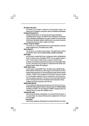
...] is selected Combined Option It allows you have to select between [SATA 1, SATA 2, SATA 3, SATA 4], [SATA 1, SATA 3, IDE 1], and [IDE 1, SATA 2, SATA 4]. ACPI HPET Table Use this motherboard to submit Windows® VistaTM certification. 3.4.4 Storage Configuration BIOS SETUP UTILITY Advanced Storage Configuration ATA/IDE Configuration SATAII_1 SATAII_2 SATAII_3 SATAII_4 IDE1 Master IDE1 Slave [Enhanced] [Hard Disk] [Not Detected] [Not Detected] [Not Detected] [Not Detected] [Not Detected] Set [Compatible] when Legacy OS (MS-DOS, Win NT) device is used. Set [Enhanced] when Native...
...] is selected Combined Option It allows you have to select between [SATA 1, SATA 2, SATA 3, SATA 4], [SATA 1, SATA 3, IDE 1], and [IDE 1, SATA 2, SATA 4]. ACPI HPET Table Use this motherboard to submit Windows® VistaTM certification. 3.4.4 Storage Configuration BIOS SETUP UTILITY Advanced Storage Configuration ATA/IDE Configuration SATAII_1 SATAII_2 SATAII_3 SATAII_4 IDE1 Master IDE1 Slave [Enhanced] [Hard Disk] [Not Detected] [Not Detected] [Not Detected] [Not Detected] [Not Detected] Set [Compatible] when Legacy OS (MS-DOS, Win NT) device is used. Set [Enhanced] when Native...
User Manual
Page 45
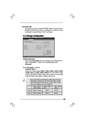
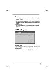
... Select Screen Select Item Change Option General Help Load Defaults Save and Exit Exit v02.54 (C) Copyright 1985-2005, American Megatrends, Inc. PCI Latency Timer The default value is recommended to enable or disable the S.M.A.R.T. (Self-Monitoring, Analysis, and Reporting Technology) feature. S.M.A.R.T. Configuration options: [Disabled], [Auto], [Enabled]. 32-Bit Data Transfer Use this item to maximize the IDE hard disk data transfer rate. 3.4.5 PCIPnP Configuration BIOS SETUP UTILITY Advanced Advanced PCI / PnP Settings PCI Latency Timer PCI IDE BusMaster [32] [Enabled...
... Select Screen Select Item Change Option General Help Load Defaults Save and Exit Exit v02.54 (C) Copyright 1985-2005, American Megatrends, Inc. PCI Latency Timer The default value is recommended to enable or disable the S.M.A.R.T. (Self-Monitoring, Analysis, and Reporting Technology) feature. S.M.A.R.T. Configuration options: [Disabled], [Auto], [Enabled]. 32-Bit Data Transfer Use this item to maximize the IDE hard disk data transfer rate. 3.4.5 PCIPnP Configuration BIOS SETUP UTILITY Advanced Advanced PCI / PnP Settings PCI Latency Timer PCI IDE BusMaster [32] [Enabled...
User Manual
Page 48
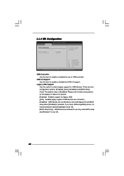
... options: [Enabled] - There are connected. [Disabled] - Enables support for USB devices. USB devices are allowed to enable or disable the USB 2.0 support. If you have USB compatibility issue, it is recommended to select [Disabled] to use only under legacy OS and BIOS setup when [Disabled] is [Enabled]. 3.4.8 USB Configuration BIOS SETUP UTILITY Advanced USB Configuration USB Controller USB 2.0 Support Legacy USB Support [Enabled] [Enabled] [Enabled] To enable or disable the onboard USB controllers. +F1 F9 F10 ESC Select Screen Select Item Change Option General Help Load Defaults...
... options: [Enabled] - There are connected. [Disabled] - Enables support for USB devices. USB devices are allowed to enable or disable the USB 2.0 support. If you have USB compatibility issue, it is recommended to select [Disabled] to use only under legacy OS and BIOS setup when [Disabled] is [Enabled]. 3.4.8 USB Configuration BIOS SETUP UTILITY Advanced USB Configuration USB Controller USB 2.0 Support Legacy USB Support [Enabled] [Enabled] [Enabled] To enable or disable the onboard USB controllers. +F1 F9 F10 ESC Select Screen Select Item Change Option General Help Load Defaults...
User Manual
Page 51
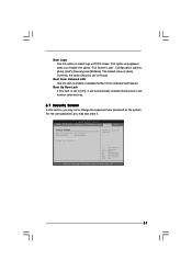
... [Auto]. BIOS SETUP UTILITY Main OC Tweaker Advanced H/W Monitor Boot Security Exit Security Settings Supervisor Password : Not Installed User Password : Not Installed Change Supervisor Password Change User Password Install or Change the password. Boot Up Num-Lock If this item is set to [On], it . For the user password, you may set or change the supervisor/user password for the system. Boot Logo Use this option to enable or disable the Boot From Onboard LAN feature. The default value is set to Aircraft. Configuration options: [Auto], [EuP], [Scenery] and [ASRock].
... [Auto]. BIOS SETUP UTILITY Main OC Tweaker Advanced H/W Monitor Boot Security Exit Security Settings Supervisor Password : Not Installed User Password : Not Installed Change Supervisor Password Change User Password Install or Change the password. Boot Up Num-Lock If this item is set to [On], it . For the user password, you may set or change the supervisor/user password for the system. Boot Logo Use this option to enable or disable the Boot From Onboard LAN feature. The default value is set to Aircraft. Configuration options: [Auto], [EuP], [Scenery] and [ASRock].
User Manual
Page 53
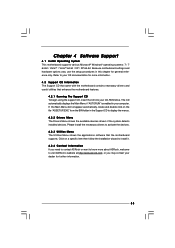
... drivers and useful utilities that the motherboard supports. Click on the file "ASSETUP.EXE" from the BIN folder in the Support CD to your CD-ROM drive. Refer to display the menus. 4.2.2 Drivers Menu The Drivers Menu shows the available devices drivers if the system detects installed devices. The CD automatically displays the Main Menu if "AUTORUN" is enabled in this chapter for general reference only. If the Main Menu did not appear automatically, locate...
... drivers and useful utilities that the motherboard supports. Click on the file "ASSETUP.EXE" from the BIN folder in the Support CD to your CD-ROM drive. Refer to display the menus. 4.2.2 Drivers Menu The Drivers Menu shows the available devices drivers if the system detects installed devices. The CD automatically displays the Main Menu if "AUTORUN" is enabled in this chapter for general reference only. If the Main Menu did not appear automatically, locate...
Quick Installation Guide
Page 2
...) 26 PCI Express x1 Slot (PCIE2) 10 Chassis Fan Connector (CHA_FAN1) 27 EUP Audio Jumper (EUP_AUDIO1) 11 IDE1 Connector (IDE1, Blue) 28 EUP LAN Jumper (EUP_LAN1) 12 Third SATAII Connector (SATAII_3; Yellow) 21 Floppy Connector (FLOPPY1) 6 2 x 240-pin DDR3 DIMM Slots 22 Print Port Header (LPT1, Purple) (Dual Channel: DDR3_A1, DDR3_B1; Motherboard Layout (G41C-GS / G41C-S) English 1 PS2_USB_PWR1 Jumper 16 Primary SATAII Connector (SATAII_1; Red) 2 ASRock G41C-GS / G41C-S Motherboard Red) 2 ATX 12V Connector (ATX12V2) 17 USB 2.0 Header (USB6_7, Blue) 3 CPU Fan Connector...
...) 26 PCI Express x1 Slot (PCIE2) 10 Chassis Fan Connector (CHA_FAN1) 27 EUP Audio Jumper (EUP_AUDIO1) 11 IDE1 Connector (IDE1, Blue) 28 EUP LAN Jumper (EUP_LAN1) 12 Third SATAII Connector (SATAII_3; Yellow) 21 Floppy Connector (FLOPPY1) 6 2 x 240-pin DDR3 DIMM Slots 22 Print Port Header (LPT1, Purple) (Dual Channel: DDR3_A1, DDR3_B1; Motherboard Layout (G41C-GS / G41C-S) English 1 PS2_USB_PWR1 Jumper 16 Primary SATAII Connector (SATAII_1; Red) 2 ASRock G41C-GS / G41C-S Motherboard Red) 2 ATX 12V Connector (ATX12V2) 17 USB 2.0 Header (USB6_7, Blue) 3 CPU Fan Connector...
Quick Installation Guide
Page 7
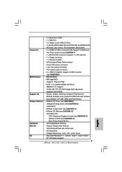
...CPU/Chassis/Power Fan Tachometer - - 1 x Serial Port: COM1 - 1 x VGA Port - 4 x Ready-to-Use USB 2.0 Ports - 1 x RJ-45 LAN Port with LED (ACT/LINK LED and SPEED LED) - Supports "Plug and Play" - ASRock OC Tuner (see CAUTION 12) - CPU Frequency Stepless Control (see CAUTION 14) - ASRock U-COP (see CAUTION 13) - ASRock Instant Flash (see CAUTION 8) - 8Mb AMI BIOS - Microsoft® Windows® 7 / 7 64-bit / VistaTM / VistaTM 64-bit / XP / XP 64-bit compliant 7 ASRock G41C-GS / G41C-S Motherboard CPU/Chassis/Power FAN connector - 24 pin ATX power connector - 4 pin...
...CPU/Chassis/Power Fan Tachometer - - 1 x Serial Port: COM1 - 1 x VGA Port - 4 x Ready-to-Use USB 2.0 Ports - 1 x RJ-45 LAN Port with LED (ACT/LINK LED and SPEED LED) - Supports "Plug and Play" - ASRock OC Tuner (see CAUTION 12) - CPU Frequency Stepless Control (see CAUTION 14) - ASRock U-COP (see CAUTION 13) - ASRock Instant Flash (see CAUTION 8) - 8Mb AMI BIOS - Microsoft® Windows® 7 / 7 64-bit / VistaTM / VistaTM 64-bit / XP / XP 64-bit compliant 7 ASRock G41C-GS / G41C-S Motherboard CPU/Chassis/Power FAN connector - 24 pin ATX power connector - 4 pin...
Quick Installation Guide
Page 9
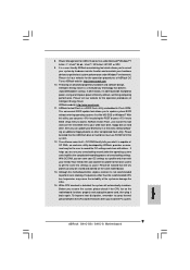
... key to BIOS setup menu to your USB flash drive, floppy disk or hard drive, then you what it is a revolutionary technology that the USB flash drive or hard drive must use FAT32/16/12 file system. 12. In other words, it back again. Please visit our website for the user to save your overclocking record under Microsoft® Windows® 7 64-bit / 7 / VistaTM 64-bit / VistaTM / XP 64-bit / XP SP1 or SP2. 9. The software...
... key to BIOS setup menu to your USB flash drive, floppy disk or hard drive, then you what it is a revolutionary technology that the USB flash drive or hard drive must use FAT32/16/12 file system. 12. In other words, it back again. Please visit our website for the user to save your overclocking record under Microsoft® Windows® 7 64-bit / 7 / VistaTM 64-bit / VistaTM / XP 64-bit / XP SP1 or SP2. 9. The software...
Quick Installation Guide
Page 19
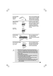
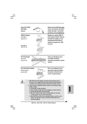
... the panel wire on the motherboard. If you use AC'97 audio panel, please install it to [Enabled]. 19 ASRock G41C-GS / G41C-S Motherboard English B. MIC_RET and OUT_RET are two USB 2.0 headers on this motherboard. E. Set the Front Panel Control option from [Auto] to the front panel audio header as below: A. Each USB 2.0 header can be connected to the SATA / SATAII hard disk or the SATAII connector on the chassis must support HDA to connect them for front panel audio cable that allows convenient connection of printer devices. D. Connect Ground...
... the panel wire on the motherboard. If you use AC'97 audio panel, please install it to [Enabled]. 19 ASRock G41C-GS / G41C-S Motherboard English B. MIC_RET and OUT_RET are two USB 2.0 headers on this motherboard. E. Set the Front Panel Control option from [Auto] to the front panel audio header as below: A. Each USB 2.0 header can be connected to the SATA / SATAII hard disk or the SATAII connector on the chassis must support HDA to connect them for front panel audio cable that allows convenient connection of printer devices. D. Connect Ground...
Quick Installation Guide
Page 21
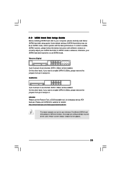
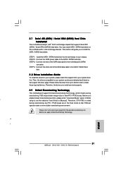
... enable Untied Overclocking function, please enter "Overclock Mode" option of your optical drive first. Before you install can operate under a more stable overclocking environment. STEP 3: Connect one end of the SATA data cable to the SATA / SATAII hard disk. 2.8 Driver Installation Guide To install the drivers to your system, please insert the support CD to your chassis. Please refer to your system can be auto-detected and listed on page 8 for internal storage devices. English 21 ASRock G41C-GS / G41C-S Motherboard n 13 1 2.7 Serial...
... enable Untied Overclocking function, please enter "Overclock Mode" option of your optical drive first. Before you install can operate under a more stable overclocking environment. STEP 3: Connect one end of the SATA data cable to the SATA / SATAII hard disk. 2.8 Driver Installation Guide To install the drivers to your system, please insert the support CD to your chassis. Please refer to your system can be auto-detected and listed on page 8 for internal storage devices. English 21 ASRock G41C-GS / G41C-S Motherboard n 13 1 2.7 Serial...
Quick Installation Guide
Page 22
... the reset button on the file "ASSETUP.EXE" from the BIN folder in the Support CD to enter BIOS Setup utility; The BIOS Setup program is a menu-driven program, which allows you start up the computer, please press during the Power-On-Self-Test (POST) to display the menus. 22 ASRock G41C-GS / G41C-S Motherboard English Software Support CD information This motherboard supports various Microsoft® Windows® operating systems: 7 / 7 64-bit / VistaTM / VistaTM 64-bit / XP...
... the reset button on the file "ASSETUP.EXE" from the BIN folder in the Support CD to enter BIOS Setup utility; The BIOS Setup program is a menu-driven program, which allows you start up the computer, please press during the Power-On-Self-Test (POST) to display the menus. 22 ASRock G41C-GS / G41C-S Motherboard English Software Support CD information This motherboard supports various Microsoft® Windows® operating systems: 7 / 7 64-bit / VistaTM / VistaTM 64-bit / XP...


