User Manual
Page 3
Contents 1 Introduction 5 1.1 Package Contents 5 1.2 Specifications 6 1.3 Motherboard Layout (G41C-GS / G41C-S 11 1.4 I/O Panel (G41C-GS 12 1.5 I/O Panel (G41C-S 13 2 Installation 14 2.1 Screw Holes 14 2.2 Pre-installation Precautions 14 2.3 CPU Installation 15 2.4 Installation of...SATA) / Serial ATAII (SATAII) Hard Disks Installation 26 2.11 Driver Installation Guide 26 2.12 Untied Overclocking Technology 26 3 BIOS SETUP UTILITY 27 3.1 Introduction 27 3.1.1 BIOS Menu Bar 27 3.1.2 Navigation Keys 28 3.2 Main Screen 28 3.3 OC Tweaker Screen 30 3.4 Advanced Screen 34 3.4.1 CPU ...
Contents 1 Introduction 5 1.1 Package Contents 5 1.2 Specifications 6 1.3 Motherboard Layout (G41C-GS / G41C-S 11 1.4 I/O Panel (G41C-GS 12 1.5 I/O Panel (G41C-S 13 2 Installation 14 2.1 Screw Holes 14 2.2 Pre-installation Precautions 14 2.3 CPU Installation 15 2.4 Installation of...SATA) / Serial ATAII (SATAII) Hard Disks Installation 26 2.11 Driver Installation Guide 26 2.12 Untied Overclocking Technology 26 3 BIOS SETUP UTILITY 27 3.1 Introduction 27 3.1.1 BIOS Menu Bar 27 3.1.2 Navigation Keys 28 3.2 Main Screen 28 3.3 OC Tweaker Screen 30 3.4 Advanced Screen 34 3.4.1 CPU ...
User Manual
Page 5
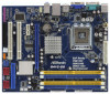
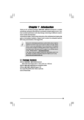
... for purchasing ASRock G41C-GS / G41C-S motherboard, a reliable motherboard produced under ASRock's consistently stringent quality control. Because the motherboard specifications and the BIOS software might be updated, the content of the Support CD. www.asrock.com/support/index.asp 1.1 Package Contents ASRock G41C-GS / G41C-S Motherboard (Micro ATX Form Factor: 9.6-in x 7.8-in, 24.4 cm x 19.8 cm) ASRock G41C-GS / G41C-S Quick Installation Guide ASRock G41C-GS / G41C-S Support CD...
... for purchasing ASRock G41C-GS / G41C-S motherboard, a reliable motherboard produced under ASRock's consistently stringent quality control. Because the motherboard specifications and the BIOS software might be updated, the content of the Support CD. www.asrock.com/support/index.asp 1.1 Package Contents ASRock G41C-GS / G41C-S Motherboard (Micro ATX Form Factor: 9.6-in x 7.8-in, 24.4 cm x 19.8 cm) ASRock G41C-GS / G41C-S Quick Installation Guide ASRock G41C-GS / G41C-S Support CD...
User Manual
Page 7
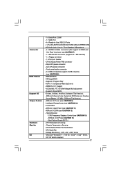
... Suite (CyberLink DVD Suite and Creative Sound Blaster X-Fi MB) (OEM and Trial Version) - Instant Boot - Supports Smart BIOS - ASRock Instant Flash (see CAUTION 8) - 8Mb AMI BIOS - AMI Legal BIOS - CPU Quiet Fan - Boot Failure Guard (B.F.G.) - CPU/Chassis/Power Fan Tachometer - Front panel audio connector - 2 x USB 2.0 headers (support 4 USB 2.0 ports) (see CAUTION 11) - Connector...
... Suite (CyberLink DVD Suite and Creative Sound Blaster X-Fi MB) (OEM and Trial Version) - Instant Boot - Supports Smart BIOS - ASRock Instant Flash (see CAUTION 8) - 8Mb AMI BIOS - AMI Legal BIOS - CPU Quiet Fan - Boot Failure Guard (B.F.G.) - CPU/Chassis/Power Fan Tachometer - Front panel audio connector - 2 x USB 2.0 headers (support 4 USB 2.0 ports) (see CAUTION 11) - Connector...

User Manual
Page 8
...667, DDR2 800 800 DDR3 800 DDR2 667, DDR2 800 533 DDR3 800 DDR2 533 * DDR3 1333 memory modules will operate in the BIOS, applying Untied Overclocking Technology, or using the thirdparty overclocking tools. The maximum shared memory size is defined by overclocking. Please check Intel®... mode. EuP Ready (EuP ready power supply is required) (see CAUTION 15) * For detailed product information, please visit our website: http://www.asrock.com WARNING Please realize that there is a certain risk involved with 64-bit CPU, there is subject to page 22 for proper installation. 4. FCC...
...667, DDR2 800 800 DDR3 800 DDR2 667, DDR2 800 533 DDR3 800 DDR2 533 * DDR3 1333 memory modules will operate in the BIOS, applying Untied Overclocking Technology, or using the thirdparty overclocking tools. The maximum shared memory size is defined by overclocking. Please check Intel®... mode. EuP Ready (EuP ready power supply is required) (see CAUTION 15) * For detailed product information, please visit our website: http://www.asrock.com WARNING Please realize that there is a certain risk involved with 64-bit CPU, there is subject to page 22 for proper installation. 4. FCC...
User Manual
Page 9
...in a few clicks without sacrificing computing performance. Frequencies other words, it back again. This convenient BIOS update tool allows you what it is a user-friendly ASRock overclocking tool which allows you to save your overclocking record under the operating system and simplifies the... and share with others. It is not recommended to access ASRock Instant Flash. ASRock website: http://www.asrock.com 10. Just launch this motherboard offers stepless control, it is able to update system BIOS without entering operating systems first like MS-DOS or Windows®...
...in a few clicks without sacrificing computing performance. Frequencies other words, it back again. This convenient BIOS update tool allows you what it is a user-friendly ASRock overclocking tool which allows you to save your overclocking record under the operating system and simplifies the... and share with others. It is not recommended to access ASRock Instant Flash. ASRock website: http://www.asrock.com 10. Just launch this motherboard offers stepless control, it is able to update system BIOS without entering operating systems first like MS-DOS or Windows®...
User Manual
Page 11
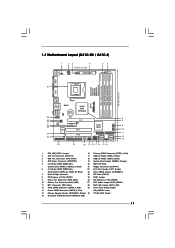
..., Lime) 14 Chassis Speaker Header (SPEAKER 1, Purple) 30 775-Pin CPU Socket 15 Secondary SATAII Connector (SATAII_2; Red) 11 1.3 Motherboard Layout (G41C-GS / G41C-S) 1 23 4 19.8cm (7.8 in) 1 PS2_USB_PWR1 ATX12V2 CPU_FAN1 56 PS2 Mouse PS2 Keyboard COM1 24.4cm (9.6 in) DDR3_B1 (64 bit, 240... CODEC CMOS Battery PCIE2 Super IO LPT1 1 CLRCMOS1 FLOPPY1 Intel G41 Chipset PCIE1 FSB1 1 PCI1 Intel ICH7 IDE1 PWR_FAN1 CHA_FAN1 PCI2 8Mb BIOS PANEL 1 PLED PWRBTN 1 HDLED RESET USB4_5 1 1 USB6_7 SATAII_1 SATAII_3 SATAII_2 SPEAKER1 1 SATAII_4 22 21 20 19 18 17 16 ...
..., Lime) 14 Chassis Speaker Header (SPEAKER 1, Purple) 30 775-Pin CPU Socket 15 Secondary SATAII Connector (SATAII_2; Red) 11 1.3 Motherboard Layout (G41C-GS / G41C-S) 1 23 4 19.8cm (7.8 in) 1 PS2_USB_PWR1 ATX12V2 CPU_FAN1 56 PS2 Mouse PS2 Keyboard COM1 24.4cm (9.6 in) DDR3_B1 (64 bit, 240... CODEC CMOS Battery PCIE2 Super IO LPT1 1 CLRCMOS1 FLOPPY1 Intel G41 Chipset PCIE1 FSB1 1 PCI1 Intel ICH7 IDE1 PWR_FAN1 CHA_FAN1 PCI2 8Mb BIOS PANEL 1 PLED PWRBTN 1 HDLED RESET USB4_5 1 1 USB6_7 SATAII_1 SATAII_3 SATAII_2 SPEAKER1 1 SATAII_4 22 21 20 19 18 17 16 ...
User Manual
Page 20
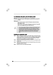
... Step 4. Remove the bracket facing the slot that you install the add-on PCI Express VGA card to PCIE1 (PCIE x16 slot) and adjust the BIOS options "Primary Graphics Adapter" to [Onboard] and "Share Memory" to install expansion cards that the power supply is switched off or the power cord is...
... Step 4. Remove the bracket facing the slot that you install the add-on PCI Express VGA card to PCIE1 (PCIE x16 slot) and adjust the BIOS options "Primary Graphics Adapter" to [Onboard] and "Share Memory" to install expansion cards that the power supply is switched off or the power cord is...
User Manual
Page 23
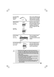
... cable that allows convenient connection of printer devices. MIC_RET and OUT_RET are two USB 2.0 headers on the chassis must support HDA to function correctly. Enter BIOS Setup Utility. If you use AC'97 audio panel, please install it to OUT2_L. Connect Audio_R (RIN) to OUT2_R and Audio_L (LIN) to the front...
... cable that allows convenient connection of printer devices. MIC_RET and OUT_RET are two USB 2.0 headers on the chassis must support HDA to function correctly. Enter BIOS Setup Utility. If you use AC'97 audio panel, please install it to OUT2_L. Connect Audio_R (RIN) to OUT2_R and Audio_L (LIN) to the front...
User Manual
Page 26
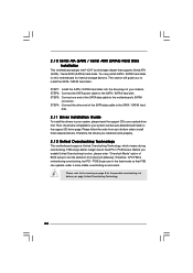
... Untied Overclocking function, please enter "Overclock Mode" option of the SATA data cable to install the SATA / SATAII hard disks. STEP 3: Connect one end of BIOS setup to set the selection from up to bottom side to [Manual]. You may install SATA / SATAII hard disks on the support CD driver page.
... Untied Overclocking function, please enter "Overclock Mode" option of the SATA data cable to install the SATA / SATAII hard disks. STEP 3: Connect one end of BIOS setup to set the selection from up to bottom side to [Manual]. You may install SATA / SATAII hard disks on the support CD driver page.
User Manual
Page 27
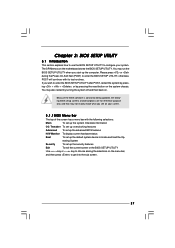
... Security To set up the default system device to locate and load the Op- You may not exactly match what you wish to enter the BIOS SETUP UTILITY after POST, restart the system by pressing + + , or by turning the system off and then back on the motherboard stores the... BIOS SETUP UTILITY. Chapter 3: BIOS SETUP UTILITY 3.1 Introduction This section explains how to use the BIOS SETUP UTILITY to configure your screen. 3.1.1BIOS Menu Bar The top of the screen has a menu bar with its...
... Security To set up the default system device to locate and load the Op- You may not exactly match what you wish to enter the BIOS SETUP UTILITY after POST, restart the system by pressing + + , or by turning the system off and then back on the motherboard stores the... BIOS SETUP UTILITY. Chapter 3: BIOS SETUP UTILITY 3.1 Introduction This section explains how to use the BIOS SETUP UTILITY to configure your screen. 3.1.1BIOS Menu Bar The top of the screen has a menu bar with its...
User Manual
Page 28
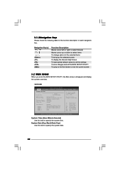
BIOS Version : G41C-GS P1.00 Processor Type : Intel (R) Core (TM) 2 Duo CPU E8200 @ 2.66GHz (64bit...Megatrends, Inc. 3.1.2Navigation Keys Please check the following table for all the settings To save changes and exit the BIOS SETUP UTILITY To jump to specify the system time. Navigation Key(s) / / + / Function Description Moves cursor ... display the General Help Screen To load optimal default values for the function description of each navigation key. G41C-GS BIOS SETUP UTILITY Main OC Tweaker Advanced H/W Monitor Boot Security Exit System Overview System Time System Date [14...
BIOS Version : G41C-GS P1.00 Processor Type : Intel (R) Core (TM) 2 Duo CPU E8200 @ 2.66GHz (64bit...Megatrends, Inc. 3.1.2Navigation Keys Please check the following table for all the settings To save changes and exit the BIOS SETUP UTILITY To jump to specify the system time. Navigation Key(s) / / + / Function Description Moves cursor ... display the General Help Screen To load optimal default values for the function description of each navigation key. G41C-GS BIOS SETUP UTILITY Main OC Tweaker Advanced H/W Monitor Boot Security Exit System Overview System Time System Date [14...
User Manual
Page 29
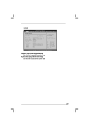
System Time [Hour:Minute:Second] Use this item to select a field. BIOS Version : G41C-S P1.00 Processor Type : Intel (R) Core (TM) 2 Duo CPU E8200 @ 2.66GHz (64bit) Processor Speed : 2666MHz Microcode Update : 10676/60C Cache Size : 6144KB Total Memory DDRII1... ESC Select Screen Select Item Change Field Select Field General Help Load Defaults Save and Exit Exit v02.54 (C) Copyright 1985-2005, American Megatrends, Inc. G41C-S BIOS SETUP UTILITY Main OC Tweaker Advanced H/W Monitor Boot Security Exit System Overview System Time System Date [14:00:09] [Tue 12/01/2009] Use [...
System Time [Hour:Minute:Second] Use this item to select a field. BIOS Version : G41C-S P1.00 Processor Type : Intel (R) Core (TM) 2 Duo CPU E8200 @ 2.66GHz (64bit) Processor Speed : 2666MHz Microcode Update : 10676/60C Cache Size : 6144KB Total Memory DDRII1... ESC Select Screen Select Item Change Field Select Field General Help Load Defaults Save and Exit Exit v02.54 (C) Copyright 1985-2005, American Megatrends, Inc. G41C-S BIOS SETUP UTILITY Main OC Tweaker Advanced H/W Monitor Boot Security Exit System Overview System Time System Date [14:00:09] [Tue 12/01/2009] Use [...
User Manual
Page 30
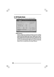
.... adjust jumper set up overclocking features. The configuration options depend on the CPU and memory module you like to save current setting as user defaults ? BIOS SETUP UTILITY Main OC Tweaker Advanced H/W Monitor Boot Security Exit OC Tweaker Settings DRAM Frequency DRAM Timing Configuration Ratio CMOS Setting 8 Intel (R) SpeedStep (tm) tech...
.... adjust jumper set up overclocking features. The configuration options depend on the CPU and memory module you like to save current setting as user defaults ? BIOS SETUP UTILITY Main OC Tweaker Advanced H/W Monitor Boot Security Exit OC Tweaker Settings DRAM Frequency DRAM Timing Configuration Ratio CMOS Setting 8 Intel (R) SpeedStep (tm) tech...
User Manual
Page 31
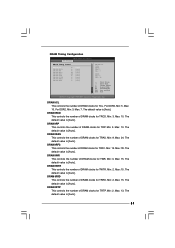
... DRAM clocks for TRCD. The default value is [Auto]. Min: 2. For DDR3, Min: 5. Min: 2. The default value is [Auto]. Max: 10. Min: 3. DRAM Timing Configuration BIOS SETUP UTILITY OC Tweaker DRAM Timing Control DRAM tCL 6 DRAM tRCD 6 DRAM tRP 6 DRAM tRAS 15 DRAM tRFC 44 DRAM tWR 6 DRAM tWTR 4 DRAM tRRD...
... DRAM clocks for TRCD. The default value is [Auto]. Min: 2. For DDR3, Min: 5. Min: 2. The default value is [Auto]. Max: 10. Min: 3. DRAM Timing Configuration BIOS SETUP UTILITY OC Tweaker DRAM Timing Control DRAM tCL 6 DRAM tRCD 6 DRAM tRP 6 DRAM tRAS 15 DRAM tRFC 44 DRAM tWR 6 DRAM tWTR 4 DRAM tRRD...
User Manual
Page 34
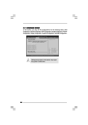
3.4 Advanced Screen In this section may cause the system to malfunction. BIOS SETUP UTILITY Main OC Tweaker Advanced H/W Monitor Boot Security Exit Advanced Settings Options for the following items: CPU Configuration, Chipset Configuration, ...may cause system to malfunction. 34 CPU Configuration Chipset Configuration ACPI Configuration Storage Configuration PCIPnP Configuration Floppy Configuration SuperIO Configuration USB Configuration BIOS Update Utility ASRock Instant Flash Select Screen Select Item Enter Go to Sub Screen F1 General Help F9 Load Defaults F10 Save and Exit ESC ...
3.4 Advanced Screen In this section may cause the system to malfunction. BIOS SETUP UTILITY Main OC Tweaker Advanced H/W Monitor Boot Security Exit Advanced Settings Options for the following items: CPU Configuration, Chipset Configuration, ...may cause system to malfunction. 34 CPU Configuration Chipset Configuration ACPI Configuration Storage Configuration PCIPnP Configuration Floppy Configuration SuperIO Configuration USB Configuration BIOS Update Utility ASRock Instant Flash Select Screen Select Item Enter Go to Sub Screen F1 General Help F9 Load Defaults F10 Save and Exit ESC ...
User Manual
Page 35
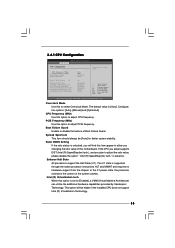
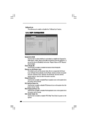
... Machine Architecture) can utilize the additional hardware capabilities provided by Vanderpool Technology. Configuration options: [Auto], [Manual] and [Optimized]. in advance. Intel (R) Virtualization tech. 3.4.1 CPU Configuration BIOS SETUP UTILITY Advanced CPU Configuration Overclock Mode CPU Frequency (MHz) PCIE Frequency (MHz) Boot Failure Guard Spread Spectrum Ratio CMOS Setting 8 Enhanced Halt State Intel...
... Machine Architecture) can utilize the additional hardware capabilities provided by Vanderpool Technology. Configuration options: [Auto], [Manual] and [Optimized]. in advance. Intel (R) Virtualization tech. 3.4.1 CPU Configuration BIOS SETUP UTILITY Advanced CPU Configuration Overclock Mode CPU Frequency (MHz) PCIE Frequency (MHz) Boot Failure Guard Spread Spectrum Ratio CMOS Setting 8 Enhanced Halt State Intel...
User Manual
Page 37
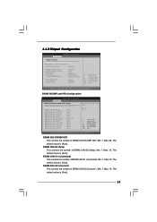
DRAM RCOMP and tRD Configuration BIOS SETUP UTILITY Advanced DRAM RCOMP STRENGTH Settings DRAM CH0 RCOMP Settings : 54-0-11-6-6-6-6 DRAM CH0 RCOMP ODT [Auto] DRAM CH0 G0 (Data) [Auto] DRAM CH0 ... value is [Auto]. Min: 1. Min: 1. DRAM CH0 G0 (Data) This controls the number of DRAM CH0 G1 (Command). The default value is [Auto]. 3.4.2 Chipset Configuration BIOS SETUP UTILITY Advanced Chipset Settings DRAM RCOMP and tRD Configuration DRAM DLL SKEW Configuration Fixed Mode Operation [Enabled] Intelligent Energy Saver Primary Graphics Adapter Shared...
DRAM RCOMP and tRD Configuration BIOS SETUP UTILITY Advanced DRAM RCOMP STRENGTH Settings DRAM CH0 RCOMP Settings : 54-0-11-6-6-6-6 DRAM CH0 RCOMP ODT [Auto] DRAM CH0 G0 (Data) [Auto] DRAM CH0 ... value is [Auto]. Min: 1. Min: 1. DRAM CH0 G0 (Data) This controls the number of DRAM CH0 G1 (Command). The default value is [Auto]. 3.4.2 Chipset Configuration BIOS SETUP UTILITY Advanced Chipset Settings DRAM RCOMP and tRD Configuration DRAM DLL SKEW Configuration Fixed Mode Operation [Enabled] Intelligent Energy Saver Primary Graphics Adapter Shared...
User Manual
Page 39
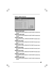
... value is [Auto]. The default value is [Auto]. DRAM CH0 CTRL1 SKEW This controls the number of DRAM CH0 CLKSET1 SKEW. DRAM DLL SKEW Configuration BIOS SETUP UTILITY Advanced DRAM DLL SKEW Settings DRAM CH0 CLKSET0 SKEW Info:0-0-0-0-0-0 DRAM CH0 CLKSET0 SKEW [Auto] DRAM CH0 CLKSET1 SKEW Info:0-0-0-0-0-0 DRAM CH0 CLKSET1...
... value is [Auto]. The default value is [Auto]. DRAM CH0 CTRL1 SKEW This controls the number of DRAM CH0 CLKSET1 SKEW. DRAM DLL SKEW Configuration BIOS SETUP UTILITY Advanced DRAM DLL SKEW Settings DRAM CH0 CLKSET0 SKEW Info:0-0-0-0-0-0 DRAM CH0 CLKSET0 SKEW [Auto] DRAM CH0 CLKSET1 SKEW Info:0-0-0-0-0-0 DRAM CH0 CLKSET1...
User Manual
Page 41
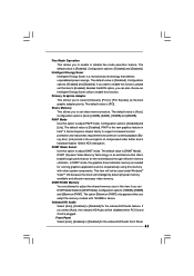
...). [Lite] mode is the encryption of compressed video buffer and is plugged. The default value is [DVMT Mode]. Configuration options: [Enabled] and [Disabled]. Besides the BIOS option, you can also choose our Intelligent Energy Saver utility to enable or disable flex mode operation feature. The option [Maximum DVMT] only appears when...
...). [Lite] mode is the encryption of compressed video buffer and is plugged. The default value is [DVMT Mode]. Configuration options: [Enabled] and [Disabled]. Besides the BIOS option, you can also choose our Intelligent Energy Saver utility to enable or disable flex mode operation feature. The option [Maximum DVMT] only appears when...
User Manual
Page 42
... disable PCI devices to boot up when the power recovers. OnBoard Lan This allows you to enable or disable the "OnBoard Lan" feature. 3.4.3 ACPI Configuration BIOS SETUP UTILITY Advanced ACPI Configuration Suspend To RAM Restore on the system from the power-soft-off mode. If you to set this item to...
... disable PCI devices to boot up when the power recovers. OnBoard Lan This allows you to enable or disable the "OnBoard Lan" feature. 3.4.3 ACPI Configuration BIOS SETUP UTILITY Advanced ACPI Configuration Suspend To RAM Restore on the system from the power-soft-off mode. If you to set this item to...


