User Manual
Page 5
In this motherboard, please visit our website for purchasing ASRock G41C-GS / G41C-S motherboard, a reliable motherboard produced under ASRock's consistently stringent quality control. Chapter 3 and 4 contain the configuration guide to quality and endurance. You may find the latest VGA cards and CPU support lists on ASRock website without notice. Because the motherboard specifications and the BIOS software might be...
In this motherboard, please visit our website for purchasing ASRock G41C-GS / G41C-S motherboard, a reliable motherboard produced under ASRock's consistently stringent quality control. Chapter 3 and 4 contain the configuration guide to quality and endurance. You may find the latest VGA cards and CPU support lists on ASRock website without notice. Because the motherboard specifications and the BIOS software might be...

User Manual
Page 6
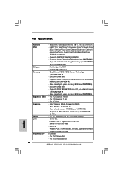
Supports EM64T CPU - Dual Channel DDR3/DDR2 Memory Technology (see CAUTION 2) - Max. Pixel Shader 4.0, DirectX 10 - Max. resolution up to 2048x1536 @ 75Hz - 5.1 CH HD Audio (VIA® VT1705 Audio Codec) - Supports FSB1333/1066/800/533 MHz - Supports Untied Overclocking Technology (see CAUTION 3) - 2 x DDR3 DIMM slots - Northbridge: Intel® G41 - G41C-GS: Realtek PCIE x1 Gigabit LAN RTL8111DL...
Supports EM64T CPU - Dual Channel DDR3/DDR2 Memory Technology (see CAUTION 2) - Max. Pixel Shader 4.0, DirectX 10 - Max. resolution up to 2048x1536 @ 75Hz - 5.1 CH HD Audio (VIA® VT1705 Audio Codec) - Supports FSB1333/1066/800/533 MHz - Supports Untied Overclocking Technology (see CAUTION 3) - 2 x DDR3 DIMM slots - Northbridge: Intel® G41 - G41C-GS: Realtek PCIE x1 Gigabit LAN RTL8111DL...
User Manual
Page 7
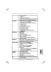
... Tuner (see CAUTION 13) - Hybrid Booster: - Chassis Temperature Sensing - Supports Smart BIOS - Instant Boot - CPU Frequency Stepless Control (see CAUTION 9) - Boot Failure Guard (B.F.G.) - CPU Temperature Sensing - Voltage Monitoring: +12V, +5V, +3.3V, Vcore - SMBIOS 2.3.1 Support - Drivers, Utilities, AntiVirus Software (Trial Version), ASRock Software Suite (CyberLink DVD Suite and Creative Sound Blaster X-Fi MB) (OEM and Trial...
... Tuner (see CAUTION 13) - Hybrid Booster: - Chassis Temperature Sensing - Supports Smart BIOS - Instant Boot - CPU Frequency Stepless Control (see CAUTION 9) - Boot Failure Guard (B.F.G.) - CPU Temperature Sensing - Voltage Monitoring: +12V, +5V, +3.3V, Vcore - SMBIOS 2.3.1 Support - Drivers, Utilities, AntiVirus Software (Trial Version), ASRock Software Suite (CyberLink DVD Suite and Creative Sound Blaster X-Fi MB) (OEM and Trial...

User Manual
Page 8
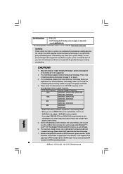
...) (see CAUTION 15) * For detailed product information, please visit our website: http://www.asrock.com WARNING Please realize that there is a certain risk involved with 64-bit CPU, there is subject to SATAII connector directly. 8 Please read the installation guide of "Hyper ...4. FCC, CE - It should be less than 4GB for the reservation for proper jumper settings. 5. This motherboard supports Untied Overclocking Technology. CPU FSB Frequency Memory Support Frequency 1333 DDR3 800, DDR3 1066, DDR3 1333 DDR2 667, DDR2 800 1066 DDR3 800, DDR3 1066 DDR2 667...
...) (see CAUTION 15) * For detailed product information, please visit our website: http://www.asrock.com WARNING Please realize that there is a certain risk involved with 64-bit CPU, there is subject to SATAII connector directly. 8 Please read the installation guide of "Hyper ...4. FCC, CE - It should be less than 4GB for the reservation for proper jumper settings. 5. This motherboard supports Untied Overclocking Technology. CPU FSB Frequency Memory Support Frequency 1333 DDR3 800, DDR3 1066, DDR3 1333 DDR2 667, DDR2 800 1066 DDR3 800, DDR3 1066 DDR2 667...
User Manual
Page 16
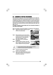
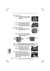
... load plate onto the IHS. While pressing down lightly on center of load lever. 16 Step 2-3. It is within the socket and properly mated to support the load plate edge, engage PnP cap with the two alignment keys of the socket. Step 4-2. Step 3. Step 2-4. Close the socket: Step 4-1. ...Step 4. Secure load lever with load plate tab under retention tab of PnP cap to match the two orientation key notches of the CPU with right hand thumb and peel the cap from the socket while pressing on load plate, engage the load lever. Step 4-3. For proper inserting...
... load plate onto the IHS. While pressing down lightly on center of load lever. 16 Step 2-3. It is within the socket and properly mated to support the load plate edge, engage PnP cap with the two alignment keys of the socket. Step 4-2. Step 3. Step 2-4. Close the socket: Step 4-1. ...Step 4. Secure load lever with load plate tab under retention tab of PnP cap to match the two orientation key notches of the CPU with right hand thumb and peel the cap from the socket while pressing on load plate, engage the load lever. Step 4-3. For proper inserting...
User Manual
Page 17
... interfere with each other components. 17 Please adopt the type of heatsink and cooling fan compliant with the CPU fan connector on the socket surface. Ensure that supports Intel 775-LAND CPU. Then connect the CPU fan to dissipate heat. Below is equipped with the motherboard throughholes. Place the heatsink onto the socket. Ensure...
... interfere with each other components. 17 Please adopt the type of heatsink and cooling fan compliant with the CPU fan connector on the socket surface. Ensure that supports Intel 775-LAND CPU. Then connect the CPU fan to dissipate heat. Below is equipped with the motherboard throughholes. Place the heatsink onto the socket. Ensure...
User Manual
Page 22
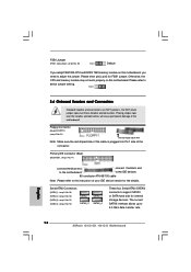
... Connector (33-pin FLOPPY1) (see p.11 No. 25) FSB1 Default If you adopt FSB1333-CPU and DDR3 1333 memory module on this motherboard, you need to adjust the jumper. Otherwise, the CPU and memory module may not work properly on this motherboard. Placing jumper caps over these headers and...are NOT jumpers. Primary IDE connector (Blue) (39-pin IDE1, see p.11, No. 13) SATAII_2 SATAII_3 SATAII_4 These four Serial ATAII (SATAII) connectors support SATAII or SATA hard disk for the details. FSB1 Jumper (FSB1, 3-pin jumper, see p.11 No. 21) Pin1 FLOPPY1 the red-striped side to ...
... Connector (33-pin FLOPPY1) (see p.11 No. 25) FSB1 Default If you adopt FSB1333-CPU and DDR3 1333 memory module on this motherboard, you need to adjust the jumper. Otherwise, the CPU and memory module may not work properly on this motherboard. Placing jumper caps over these headers and...are NOT jumpers. Primary IDE connector (Blue) (39-pin IDE1, see p.11, No. 13) SATAII_2 SATAII_3 SATAII_4 These four Serial ATAII (SATAII) connectors support SATAII or SATA hard disk for the details. FSB1 Jumper (FSB1, 3-pin jumper, see p.11 No. 21) Pin1 FLOPPY1 the red-striped side to ...
User Manual
Page 24
...) (see p.11 No. 10) GND +12V CHA_FAN_SPEED (3-pin PWR_FAN1) (see p.11 No. 3) +12V CPU_FAN_SPEED GND FAN_SPEED_CONTROL 1 2 3 4 Please connect a CPU fan cable to this connector and match the black wire to this header. If you adopt a traditional 20-pin ATX power supply. Please connect the...DUMMY RESET# GND HDLEDHDLED+ 1 SPEAKER DUMMY DUMMY +5V This header accommodates several system front panel functions. Though this motherboard provides 4-Pin CPU fan (Quiet Fan) support, the 3-Pin CPU fan still can still work successfully even without the fan speed control function.
...) (see p.11 No. 10) GND +12V CHA_FAN_SPEED (3-pin PWR_FAN1) (see p.11 No. 3) +12V CPU_FAN_SPEED GND FAN_SPEED_CONTROL 1 2 3 4 Please connect a CPU fan cable to this connector and match the black wire to this header. If you adopt a traditional 20-pin ATX power supply. Please connect the...DUMMY RESET# GND HDLEDHDLED+ 1 SPEAKER DUMMY DUMMY +5V This header accommodates several system front panel functions. Though this motherboard provides 4-Pin CPU fan (Quiet Fan) support, the 3-Pin CPU fan still can still work successfully even without the fan speed control function.
User Manual
Page 26
...SATAII hard disk. 2.11 Driver Installation Guide To install the drivers to your system, please insert the support CD to install the SATA / SATAII hard disks. Before you to your chassis. Therefore, CPU FSB is untied during overclocking, FSB enjoys better margin due to [Manual]. STEP 4: Connect the ... section will guide you enable Untied Overclocking function, please enter "Overclock Mode" option of the SATA data cable to the warning on the support CD driver page. STEP 2: Connect the SATA power cable to install those required drivers. STEP 3: Connect one end of BIOS setup to...
...SATAII hard disk. 2.11 Driver Installation Guide To install the drivers to your system, please insert the support CD to install the SATA / SATAII hard disks. Before you to your chassis. Therefore, CPU FSB is untied during overclocking, FSB enjoys better margin due to [Manual]. STEP 4: Connect the ... section will guide you enable Untied Overclocking function, please enter "Overclock Mode" option of the SATA data cable to the warning on the support CD driver page. STEP 2: Connect the SATA power cable to install those required drivers. STEP 3: Connect one end of BIOS setup to...
User Manual
Page 30
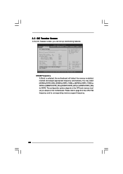
... DDR3_1066] or [667MHz DDR3_1333] for DDR3 or [266MHz DDR2_533], [333MHz DDR2_667] or [400MHz DDR2_800] for the CPU FSB frequency and its corresponding memory support frequency. 30 Please refer to page 8 for DDR2. BIOS SETUP UTILITY Main OC Tweaker Advanced H/W Monitor Boot Security...(tm) tech. DRAM Frequency If [Auto] is selected, the motherboard will detect the memory module(s) inserted and assigns appropriate frequency automatically. Overclock Mode CPU Frequency (MHz) PCIE Frequency (MHz) [Auto] [8] [Auto] [Auto] [333] [100] If you adopt on this motherboard. 3.3 OC ...
... DDR3_1066] or [667MHz DDR3_1333] for DDR3 or [266MHz DDR2_533], [333MHz DDR2_667] or [400MHz DDR2_800] for the CPU FSB frequency and its corresponding memory support frequency. 30 Please refer to page 8 for DDR2. BIOS SETUP UTILITY Main OC Tweaker Advanced H/W Monitor Boot Security...(tm) tech. DRAM Frequency If [Auto] is selected, the motherboard will detect the memory module(s) inserted and assigns appropriate frequency automatically. Overclock Mode CPU Frequency (MHz) PCIE Frequency (MHz) [Auto] [8] [Auto] [Auto] [333] [100] If you adopt on this motherboard. 3.3 OC ...
User Manual
Page 32
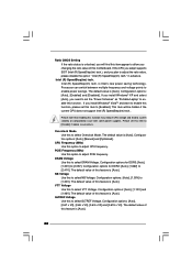
...and lead to [Enabled]. GLTREF Voltage Use this to adjust the ratio value, please disable the option " Intel (R) SpeedStep(tm) tech." If the CPU you adopt supports EIST (Intel (R) SpeedStep(tm) tech.), and you plan to select GLTREF Voltage. Intel (R) SpeedStep(tm) tech. If you install Windows® XP... DRAM Voltage Use this to enable this function. Ratio CMOS Setting If the ratio status is unlocked, you will be hidden if the current CPU does not support Intel (R) SpeedStep(tm) tech.. The default value is [Auto]. is [Auto]. 32 The default value of this feature is Intel's new...
...and lead to [Enabled]. GLTREF Voltage Use this to adjust the ratio value, please disable the option " Intel (R) SpeedStep(tm) tech." If the CPU you adopt supports EIST (Intel (R) SpeedStep(tm) tech.), and you plan to select GLTREF Voltage. Intel (R) SpeedStep(tm) tech. If you install Windows® XP... DRAM Voltage Use this to enable this function. Ratio CMOS Setting If the ratio status is unlocked, you will be hidden if the current CPU does not support Intel (R) SpeedStep(tm) tech.. The default value is [Auto]. is [Auto]. 32 The default value of this feature is Intel's new...
User Manual
Page 35
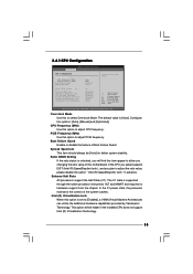
... Frequency (MHz) Use this to adjust the ratio value, please disable the option " Intel (R) SpeedStep(tm) tech." If the CPU you adopt supports EIST (Intel (R) SpeedStep(tm) tech.), and you will be [Auto] for better system stability. Enhance Halt State All processors... [Manual] and [Optimized]. Ratio CMOS Setting If the ratio status is set to adjust CPU frequency. in advance. Spread Spectrum This item should always be hidden if the installed CPU does not support Intel (R) Virtualization Technology. 35 In the C1 power state, the processor maintains the context of...
... Frequency (MHz) Use this to adjust the ratio value, please disable the option " Intel (R) SpeedStep(tm) tech." If the CPU you adopt supports EIST (Intel (R) SpeedStep(tm) tech.), and you will be [Auto] for better system stability. Enhance Halt State All processors... [Manual] and [Optimized]. Ratio CMOS Setting If the ratio status is set to adjust CPU frequency. in advance. Spread Spectrum This item should always be hidden if the installed CPU does not support Intel (R) Virtualization Technology. 35 In the C1 power state, the processor maintains the context of...

User Manual
Page 36
... and lead to system stability or compatibility issue with some power supplies. This option will be hidden if the installed CPU does not support Hyper-Threading technology. Intel (R) SpeedStep(tm) tech. If you install Windows® VistaTM and want to enable this function, please set this... value is an enhancement to execute code. The default value is Intel's new power saving technology. This item will be hidden if the current CPU does not support Intel (R) SpeedStep(tm) tech.. Please set the "Power Schemes" as Microsoft® Windows® XP. Intel (R) SpeedStep(tm) tech. ...
... and lead to system stability or compatibility issue with some power supplies. This option will be hidden if the installed CPU does not support Hyper-Threading technology. Intel (R) SpeedStep(tm) tech. If you install Windows® VistaTM and want to enable this function, please set this... value is an enhancement to execute code. The default value is Intel's new power saving technology. This item will be hidden if the current CPU does not support Intel (R) SpeedStep(tm) tech.. Please set the "Power Schemes" as Microsoft® Windows® XP. Intel (R) SpeedStep(tm) tech. ...
Quick Installation Guide
Page 5
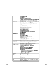
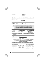
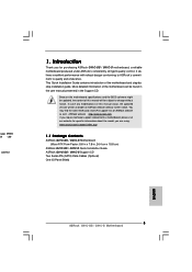
... be found in the user manual presented in , 24.4 cm x 19.8 cm) ASRock G41C-GS / G41C-S Quick Installation Guide ASRock G41C-GS / G41C-S Support CD Two Serial ATA (SATA) Data Cables (Optional) One I/O Panel Shield English 5 ASRock G41C-GS / G41C-S Motherboard You may find the latest VGA cards and CPU support lists on ASRock website without notice. Introduction Thank you for specific information about the model...
... be found in the user manual presented in , 24.4 cm x 19.8 cm) ASRock G41C-GS / G41C-S Quick Installation Guide ASRock G41C-GS / G41C-S Support CD Two Serial ATA (SATA) Data Cables (Optional) One I/O Panel Shield English 5 ASRock G41C-GS / G41C-S Motherboard You may find the latest VGA cards and CPU support lists on ASRock website without notice. Introduction Thank you for specific information about the model...
Quick Installation Guide
Page 6
... Accelerator X4500 - Supports Wake-On-LAN I /O - Supports Untied Overclocking Technology (see CAUTION 6) - Supports EM64T CPU - Supports Hyper-Threading Technology (see CAUTION 4) - Supports DDR3 1333(OC)/1066/800 non-ECC, un-buffered memory (see CAUTION 1) - 1.2 Specifications Platform CPU Chipset Memory Expansion Slot Graphics Audio LAN Rear Panel I /O Panel - 1 x PS/2 Mouse Port - 1 x PS/2 Keyboard Port 6 ASRock G41C-GS / G41C-S Motherboard English Supports DDR2 800...
... Accelerator X4500 - Supports Wake-On-LAN I /O - Supports Untied Overclocking Technology (see CAUTION 6) - Supports EM64T CPU - Supports Hyper-Threading Technology (see CAUTION 4) - Supports DDR3 1333(OC)/1066/800 non-ECC, un-buffered memory (see CAUTION 1) - 1.2 Specifications Platform CPU Chipset Memory Expansion Slot Graphics Audio LAN Rear Panel I /O Panel - 1 x PS/2 Mouse Port - 1 x PS/2 Keyboard Port 6 ASRock G41C-GS / G41C-S Motherboard English Supports DDR2 800...
Quick Installation Guide
Page 7
... Monitor - SMBIOS 2.3.1 Support - Drivers, Utilities, AntiVirus Software (Trial Version), ASRock Software Suite (CyberLink DVD Suite and Creative Sound Blaster X-Fi MB) (OEM and Trial Version) Unique Feature - Instant Boot - Hybrid Booster: - CPU Temperature Sensing - CPU Quiet Fan - Microsoft® Windows® 7 / 7 64-bit / VistaTM / VistaTM 64-bit / XP / XP 64-bit compliant 7 ASRock G41C-GS / G41C-S Motherboard ACPI...
... Monitor - SMBIOS 2.3.1 Support - Drivers, Utilities, AntiVirus Software (Trial Version), ASRock Software Suite (CyberLink DVD Suite and Creative Sound Blaster X-Fi MB) (OEM and Trial Version) Unique Feature - Instant Boot - Hybrid Booster: - CPU Temperature Sensing - CPU Quiet Fan - Microsoft® Windows® 7 / 7 64-bit / VistaTM / VistaTM 64-bit / XP / XP 64-bit compliant 7 ASRock G41C-GS / G41C-S Motherboard ACPI...
Quick Installation Guide
Page 8
... BIOS, applying Untied Overclocking Technology, or using the thirdparty overclocking tools. Please refer to SATAII connector directly. 8 ASRock G41C-GS / G41C-S Motherboard English Please check Intel® website for the CPU FSB frequency and its corresponding memory support frequency. About the setting of "Hyper Threading Technology", please check page 36 of "User Manual" in overclocking mode...
... BIOS, applying Untied Overclocking Technology, or using the thirdparty overclocking tools. Please refer to SATAII connector directly. 8 ASRock G41C-GS / G41C-S Motherboard English Please check Intel® website for the CPU FSB frequency and its corresponding memory support frequency. About the setting of "Hyper Threading Technology", please check page 36 of "User Manual" in overclocking mode...
Quick Installation Guide
Page 12
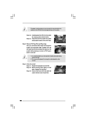
... Step 1-1. Disengaging the lever by depressing down and out on center of PnP cap to support the load plate edge, engage PnP cap with the two alignment keys of the CPU with right hand thumb and peel the cap from the socket while pressing on the hook...your left hand index finger and thumb to assist in removal. 12 ASRock G41C-GS / G41C-S Motherboard Rotate the load lever to fully open position at approximately 100 degrees. Rotate the load plate to fully open position at approximately 135 degrees. Hold the CPU by using a purely vertical motion. Step 1. Step 2. Step ...
... Step 1-1. Disengaging the lever by depressing down and out on center of PnP cap to support the load plate edge, engage PnP cap with the two alignment keys of the CPU with right hand thumb and peel the cap from the socket while pressing on the hook...your left hand index finger and thumb to assist in removal. 12 ASRock G41C-GS / G41C-S Motherboard Rotate the load lever to fully open position at approximately 100 degrees. Rotate the load plate to fully open position at approximately 135 degrees. Hold the CPU by using a purely vertical motion. Step 1. Step 2. Step ...
Quick Installation Guide
Page 18
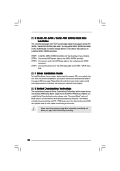
... of the motherboard! FSB1 Jumper (FSB1, 3-pin jumper, see p.2 No. 25) Default If you adopt FSB1333-CPU and DDR3 1333 memory module on this motherboard, you need to the instruction of your IDE device vendor for the... (33-pin FLOPPY1) (see p.2, No. 13) SATAII_1 SATAII_2 SATAII_3 SATAII_4 These four Serial ATAII (SATAII) connectors support SATAII or SATA hard disk for FSB1 jumper. Placing jumper caps over these headers and connectors. Please refer to Pin1.... The current SATAII interface allows up to 3.0 Gb/s data transfer rate. 18 ASRock G41C-GS / G41C-S Motherboard English
... of the motherboard! FSB1 Jumper (FSB1, 3-pin jumper, see p.2 No. 25) Default If you adopt FSB1333-CPU and DDR3 1333 memory module on this motherboard, you need to the instruction of your IDE device vendor for the... (33-pin FLOPPY1) (see p.2, No. 13) SATAII_1 SATAII_2 SATAII_3 SATAII_4 These four Serial ATAII (SATAII) connectors support SATAII or SATA hard disk for FSB1 jumper. Placing jumper caps over these headers and connectors. Please refer to Pin1.... The current SATAII interface allows up to 3.0 Gb/s data transfer rate. 18 ASRock G41C-GS / G41C-S Motherboard English

Quick Installation Guide
Page 20
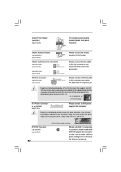
... ASRock G41C-GS / G41C-S Motherboard English CPU Fan Connector (4-pin CPU_FAN1) (see p.2 No. 2) ATX 12V plug to this connector so that it can work if you plan to connect the 3-Pin CPU fan to the CPU fan connector on this motherboard provides 4-Pin CPU fan (Quiet Fan) support, the 3-Pin CPU ...ATX 12V Connector Please note that it is necessary (4-pin ATX12V2) to connect a power supply with (see p.2 No. 3) 1 2 3 4 Please connect a CPU fan cable to this header. Chassis and Power Fan Connectors (3-pin CHA_FAN1) (see p.2 No. 10) (3-pin PWR_FAN1) (see p.2 No. 19) This header ...
... ASRock G41C-GS / G41C-S Motherboard English CPU Fan Connector (4-pin CPU_FAN1) (see p.2 No. 2) ATX 12V plug to this connector so that it can work if you plan to connect the 3-Pin CPU fan to the CPU fan connector on this motherboard provides 4-Pin CPU fan (Quiet Fan) support, the 3-Pin CPU ...ATX 12V Connector Please note that it is necessary (4-pin ATX12V2) to connect a power supply with (see p.2 No. 3) 1 2 3 4 Please connect a CPU fan cable to this header. Chassis and Power Fan Connectors (3-pin CHA_FAN1) (see p.2 No. 10) (3-pin PWR_FAN1) (see p.2 No. 19) This header ...


