
User Manual
Page 6
...2.1 Installing the CPU 11 2.2 Installing the CPU Fan and Heatsink 14 2.3 Installing Memory Modules (DIMM) 15 2.4 Expansion Slots (PCI Express Slots) 17 2.5 Jumpers Setup 18 2.6 Onboard Headers and Connectors 19 2.7 CrossFireXTM and Quad CrossFireXTM Operation Guide 24 2.7.1 Installing Two CrossFireXTM-Ready Graphics Cards 24 2.7.2 Driver Installation and Setup 26 Chapter 3 Software and Utilities Operation 27 3.1 Installing Drivers 27 3.2 Killer Network Manager 28 3.2.1 Installing Killer Network Manager 28 3.2.2 Using Killer Network Manager 28 3.3 ASRock Live Update...
...2.1 Installing the CPU 11 2.2 Installing the CPU Fan and Heatsink 14 2.3 Installing Memory Modules (DIMM) 15 2.4 Expansion Slots (PCI Express Slots) 17 2.5 Jumpers Setup 18 2.6 Onboard Headers and Connectors 19 2.7 CrossFireXTM and Quad CrossFireXTM Operation Guide 24 2.7.1 Installing Two CrossFireXTM-Ready Graphics Cards 24 2.7.2 Driver Installation and Setup 26 Chapter 3 Software and Utilities Operation 27 3.1 Installing Drivers 27 3.2 Killer Network Manager 28 3.2.1 Installing Killer Network Manager 28 3.2.2 Using Killer Network Manager 28 3.3 ASRock Live Update...

User Manual
Page 7
...37 3.4.1 Live Streaming Your Gameplay 37 3.4.2 Recording Your Gameplay 40 3.5 Enabling USB Ports for Windows® 7 Installation 41 Chapter 4 UEFI SETUP UTILITY 44 4.1 Introduction 44 4.1.1 UEFI Menu Bar 44 4.1.2 Navigation Keys 45 4.2 Main Screen 46 4.3 OC Tweaker Screen 47 4.4 Advanced Screen 57 4.4.1 CPU Configuration 58 4.4.2 Chipset Configuration 60 4.4.3 Storage Configuration 63 4.4.4 Super IO Configuration 64 4.4.5 ACPI Configuration 65 4.4.6 USB Configuration 67 4.4.7 Trusted Computing 68 4.5 Tools 69 4.6 Hardware Health Event Monitoring Screen 73
...37 3.4.1 Live Streaming Your Gameplay 37 3.4.2 Recording Your Gameplay 40 3.5 Enabling USB Ports for Windows® 7 Installation 41 Chapter 4 UEFI SETUP UTILITY 44 4.1 Introduction 44 4.1.1 UEFI Menu Bar 44 4.1.2 Navigation Keys 45 4.2 Main Screen 46 4.3 OC Tweaker Screen 47 4.4 Advanced Screen 57 4.4.1 CPU Configuration 58 4.4.2 Chipset Configuration 60 4.4.3 Storage Configuration 63 4.4.4 Super IO Configuration 64 4.4.5 ACPI Configuration 65 4.4.6 USB Configuration 67 4.4.7 Trusted Computing 68 4.5 Tools 69 4.6 Hardware Health Event Monitoring Screen 73
User Manual
Page 9
... • ASRock Fatal1ty B150 Gaming K4 Series Motherboard (ATX Form Factor) • ASRock Fatal1ty B150 Gaming K4 Series Quick Installation Guide • ASRock Fatal1ty B150 Gaming K4 Series Support CD • 2 x Serial ATA (SATA) Data Cables (Optional) • 1 x I/O Panel Shield 1 English It delivers excellent performance with robust design conforming to ASRock's commitment to change without further notice. You may find the latest VGA cards and CPU support list on ASRock's website without notice. Chapter 3 contains the operation guide of the software and utilities.
... • ASRock Fatal1ty B150 Gaming K4 Series Motherboard (ATX Form Factor) • ASRock Fatal1ty B150 Gaming K4 Series Quick Installation Guide • ASRock Fatal1ty B150 Gaming K4 Series Support CD • 2 x Serial ATA (SATA) Data Cables (Optional) • 1 x I/O Panel Shield 1 English It delivers excellent performance with robust design conforming to ASRock's commitment to change without further notice. You may find the latest VGA cards and CPU support list on ASRock's website without notice. Chapter 3 contains the operation guide of the software and utilities.
User Manual
Page 11
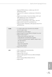
... and HBR (High Bit Rate Audio) with HDMI Port (Compliant HDMI monitor is required) • Supports Accelerated Media Codecs: HEVC, VP8, VP9 • Supports HDCP with DVI-D and HDMI Ports • Supports Full HD 1080p Blu-ray (BD) playback with DVI-D and HDMI Ports • 7.1 CH HD Audio with Differential Amplifier - Fatal1ty B150 Gaming K4 Series Audio LAN • Supports HDMI with max. Pure Power-In - PCB Isolate Shielding • Supports DTS Connect • PCIE x1 Gigabit LAN 10/100...
... and HBR (High Bit Rate Audio) with HDMI Port (Compliant HDMI monitor is required) • Supports Accelerated Media Codecs: HEVC, VP8, VP9 • Supports HDCP with DVI-D and HDMI Ports • Supports Full HD 1080p Blu-ray (BD) playback with DVI-D and HDMI Ports • 7.1 CH HD Audio with Differential Amplifier - Fatal1ty B150 Gaming K4 Series Audio LAN • Supports HDMI with max. Pure Power-In - PCB Isolate Shielding • Supports DTS Connect • PCIE x1 Gigabit LAN 10/100...
User Manual
Page 12
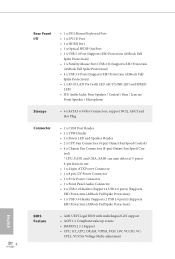
... 1 x USB 3.0 Header (Supports 2 USB 3.0 ports) (Supports ESD Protection (ASRock Full Spike Protection)) English BIOS Feature • AMI UEFI Legal BIOS with LED (ACT/LINK LED and SPEED LED) • HD Audio Jacks: Rear Speaker / Central / Bass / Line in / Front Speaker / Microphone Storage • 6 x SATA3 6.0 Gb/s Connectors, support NCQ, AHCI and Hot Plug Connector • 1 x COM Port Header • 1 x TPM Header • 1 x Power LED and Speaker Header • 2 x CPU Fan Connectors (4-pin) (Smart Fan Speed Control) • 4 x Chassis Fan Connectors (4-pin) (Smart Fan Speed Con...
... 1 x USB 3.0 Header (Supports 2 USB 3.0 ports) (Supports ESD Protection (ASRock Full Spike Protection)) English BIOS Feature • AMI UEFI Legal BIOS with LED (ACT/LINK LED and SPEED LED) • HD Audio Jacks: Rear Speaker / Central / Bass / Line in / Front Speaker / Microphone Storage • 6 x SATA3 6.0 Gb/s Connectors, support NCQ, AHCI and Hot Plug Connector • 1 x COM Port Header • 1 x TPM Header • 1 x Power LED and Speaker Header • 2 x CPU Fan Connectors (4-pin) (Smart Fan Speed Control) • 4 x Chassis Fan Connectors (4-pin) (Smart Fan Speed Con...
User Manual
Page 13
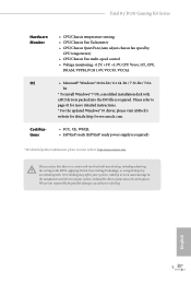
... instructions. * For the updated Windows® 10 driver, please visit ASRock's website for possible damage caused by CPU temperature) • CPU/Chassis Fan multi-speed control • Voltage monitoring: +12V, +5V, +3.3V, CPU Vcore, GT_CPU, DRAM, VPPM, PCH 1.0V, VCCIO, VCCSA OS • Microsoft® Windows® 10 64-bit / 8.1 64-bit / 7 32-bit / 7 64- We are not responsible for details: http://www.asrock.com. Fatal1ty B150 Gaming K4 Series Hardware Monitor • CPU/Chassis temperature sensing • CPU/Chassis Fan Tachometer • CPU/Chassis...
... instructions. * For the updated Windows® 10 driver, please visit ASRock's website for possible damage caused by CPU temperature) • CPU/Chassis Fan multi-speed control • Voltage monitoring: +12V, +5V, +3.3V, CPU Vcore, GT_CPU, DRAM, VPPM, PCH 1.0V, VCCIO, VCCSA OS • Microsoft® Windows® 10 64-bit / 8.1 64-bit / 7 32-bit / 7 64- We are not responsible for details: http://www.asrock.com. Fatal1ty B150 Gaming K4 Series Hardware Monitor • CPU/Chassis temperature sensing • CPU/Chassis Fan Tachometer • CPU/Chassis...
User Manual
Page 15
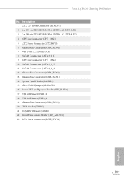
...Fatal1ty B150 Gaming K4 Series No. Description 1 ATX 12V Power Connector (ATX12V1) 2 2 x 288-pin DDR4 DIMM Slots (DDR4_A1, DDR4_B1) 3 2 x 288-pin DDR4 DIMM Slots (DDR4_A2, DDR4_B2) 4 CPU Fan Connector (CPU_FAN1) 5 ATX Power Connector (ATXPWR1) 6 Chassis Fan Connector (CHA_FAN4) 7 USB 3.0 Header (USB3_7_8) 8 SATA3 Connectors (SATA3_0_1) 9 CPU Fan Connector (CPU_FAN2) 10 SATA3 Connectors (SATA3_3_5) 11 SATA3 Connectors (SATA3_2_4) 12 Chassis Fan Connector (CHA_FAN2) 13 Chassis Fan Connector (CHA_FAN1) 14 System Panel Header (PANEL1) 15 Clear CMOS Jumper (CLRMOS1) 16 Power LED and Speaker Header...
...Fatal1ty B150 Gaming K4 Series No. Description 1 ATX 12V Power Connector (ATX12V1) 2 2 x 288-pin DDR4 DIMM Slots (DDR4_A1, DDR4_B1) 3 2 x 288-pin DDR4 DIMM Slots (DDR4_A2, DDR4_B2) 4 CPU Fan Connector (CPU_FAN1) 5 ATX Power Connector (ATXPWR1) 6 Chassis Fan Connector (CHA_FAN4) 7 USB 3.0 Header (USB3_7_8) 8 SATA3 Connectors (SATA3_0_1) 9 CPU Fan Connector (CPU_FAN2) 10 SATA3 Connectors (SATA3_3_5) 11 SATA3 Connectors (SATA3_2_4) 12 Chassis Fan Connector (CHA_FAN2) 13 Chassis Fan Connector (CHA_FAN1) 14 System Panel Header (PANEL1) 15 Clear CMOS Jumper (CLRMOS1) 16 Power LED and Speaker Header...
User Manual
Page 23
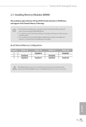
... to the motherboard and the DIMM if you always need to install a DDR, DDR2 or DDR3 memory module into the slot at incorrect orientation. Fatal1ty B150 Gaming K4 Series 2.3 Installing Memory Modules (DIMM) This motherboard provides four 288-pin DDR4 (Double Data Rate 4) DIMM slots, and supports Dual Channel Memory Technology. 1. For dual channel configuration, you force the DIMM into a DDR4 slot; It is not allowed to install identical (the same brand, speed, size and chip-type) DDR4...
... to the motherboard and the DIMM if you always need to install a DDR, DDR2 or DDR3 memory module into the slot at incorrect orientation. Fatal1ty B150 Gaming K4 Series 2.3 Installing Memory Modules (DIMM) This motherboard provides four 288-pin DDR4 (Double Data Rate 4) DIMM slots, and supports Dual Channel Memory Technology. 1. For dual channel configuration, you force the DIMM into a DDR4 slot; It is not allowed to install identical (the same brand, speed, size and chip-type) DDR4...

User Manual
Page 25
... connect a chassis fan to the motherboard's chassis fan connector (CHA_FAN1, CHA_FAN2, CHA_FAN3 or CHA_FAN4) when using multiple graphics cards. 17 English Fatal1ty B150 Gaming K4 Series 2.4 Expansion Slots (PCI Express Slots) There are 5 PCI Express slots on the motherboard. Before installing an expansion card, please make necessary hardware settings for PCI Express x1 lane width cards. PCIE5 (PCIe 3.0 x1 slot) is unplugged. Please read the documentation of the expansion card and make sure that the power supply is switched off or the power cord is used for...
... connect a chassis fan to the motherboard's chassis fan connector (CHA_FAN1, CHA_FAN2, CHA_FAN3 or CHA_FAN4) when using multiple graphics cards. 17 English Fatal1ty B150 Gaming K4 Series 2.4 Expansion Slots (PCI Express Slots) There are 5 PCI Express slots on the motherboard. Before installing an expansion card, please make necessary hardware settings for PCI Express x1 lane width cards. PCIE5 (PCIe 3.0 x1 slot) is unplugged. Please read the documentation of the expansion card and make sure that the power supply is switched off or the power cord is used for...
User Manual
Page 27
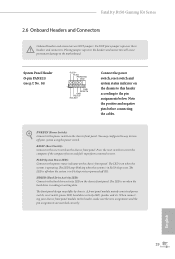
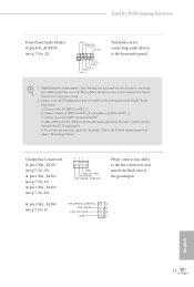
... the chassis front panel. PWRBTN (Power Switch): Connect to the pin assignments below. The LED keeps blinking when the system is in S1/S3 sleep state. The LED is on when the hard drive is operating. The LED is on when the system is reading or writing data. English 19 The front panel design may configure the way to perform a normal restart. Fatal1ty B150 Gaming K4 Series 2.6 Onboard Headers and Connectors Onboard headers and connectors...
... the chassis front panel. PWRBTN (Power Switch): Connect to the pin assignments below. The LED keeps blinking when the system is in S1/S3 sleep state. The LED is on when the hard drive is operating. The LED is on when the system is reading or writing data. English 19 The front panel design may configure the way to perform a normal restart. Fatal1ty B150 Gaming K4 Series 2.6 Onboard Headers and Connectors Onboard headers and connectors...
User Manual
Page 29
Fatal1ty B150 Gaming K4 Series Front Panel Audio Header (9-pin HD_AUDIO1) (see p.7, No. 6) FAN_SPEED_CONTROL 4 FAN_SPEED 3 FAN_VOLTAGE 2 GND 1 English 21 E. Connect Ground (GND) to OUT2_L. Connect Audio_R (RIN) to OUT2_R and Audio_L (LIN) to Ground (GND). Connect Mic_IN (MIC) to the "FrontMic" Tab in our manual and chassis manual to connect them for the AC'97 audio panel. MIC_RET and OUT_RET are for connecting audio devices to the front audio panel. 1. To activate the front...
Fatal1ty B150 Gaming K4 Series Front Panel Audio Header (9-pin HD_AUDIO1) (see p.7, No. 6) FAN_SPEED_CONTROL 4 FAN_SPEED 3 FAN_VOLTAGE 2 GND 1 English 21 E. Connect Ground (GND) to OUT2_L. Connect Audio_R (RIN) to OUT2_R and Audio_L (LIN) to Ground (GND). Connect Mic_IN (MIC) to the "FrontMic" Tab in our manual and chassis manual to connect them for the AC'97 audio panel. MIC_RET and OUT_RET are for connecting audio devices to the front audio panel. 1. To activate the front...
User Manual
Page 31
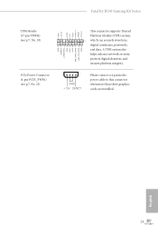
... connect a 4 pin molex power cable to this connector when more than three graphics cards are installed. English 23 A TPM system also helps enhance network security, protects digital identities, and ensures platform integrity. Fatal1ty B150 Gaming K4 Series TPM Header (17-pin TPMS1) (see p.7, No. 20) PCIe Power Connector (4-pin PCIE_PWR1) (see p.7, No. 23) GND SERIRQ # S_PWRDWN # GN D LAD1 LAD2 SMB_DATA_MAIN SMB_CLK_MAIN GN D +3VS B LAD0 +3V LAD3 PCIRST # FRAM E PCICLK This connector supports...
... connect a 4 pin molex power cable to this connector when more than three graphics cards are installed. English 23 A TPM system also helps enhance network security, protects digital identities, and ensures platform integrity. Fatal1ty B150 Gaming K4 Series TPM Header (17-pin TPMS1) (see p.7, No. 20) PCIe Power Connector (4-pin PCIE_PWR1) (see p.7, No. 23) GND SERIRQ # S_PWRDWN # GN D LAD1 LAD2 SMB_DATA_MAIN SMB_CLK_MAIN GN D +3VS B LAD0 +3V LAD3 PCIRST # FRAM E PCICLK This connector supports...

User Manual
Page 32
... the slots. Download the drivers from the AMD's website: www.amd.com 3. 2.7 CrossFireXTM and Quad CrossFireXTM Operation Guide This motherboard supports CrossFireXTM and Quad CrossFireXTM that allows you to install up to enable CrossFireXTM. Make sure that your power supply unit (PSU) can provide at least the minimum power your graphics card vendor for details. 4. Different CrossFireXTM cards may require different methods to three identical PCI Express x16 graphics cards...
... the slots. Download the drivers from the AMD's website: www.amd.com 3. 2.7 CrossFireXTM and Quad CrossFireXTM Operation Guide This motherboard supports CrossFireXTM and Quad CrossFireXTM that allows you to install up to enable CrossFireXTM. Make sure that your power supply unit (PSU) can provide at least the minimum power your graphics card vendor for details. 4. Different CrossFireXTM cards may require different methods to three identical PCI Express x16 graphics cards...
User Manual
Page 34
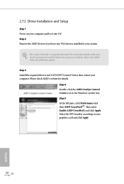
... is an optional download. Step 3 Install the required drivers and CATALYST Control Center then restart your computer and boot into OS. Step 5 In the left pane, click Performance and then AMD CrossFireXTM. Please check AMD's website for AMD driver updates. Select the GPU number according to installation. Please check AMD's website for details. Step 2 Remove the AMD drivers if you have any previously installed Catalyst drivers prior to...
... is an optional download. Step 3 Install the required drivers and CATALYST Control Center then restart your computer and boot into OS. Step 5 In the left pane, click Performance and then AMD CrossFireXTM. Please check AMD's website for AMD driver updates. Select the GPU number according to installation. Please check AMD's website for details. Step 2 Remove the AMD drivers if you have any previously installed Catalyst drivers prior to...
User Manual
Page 35
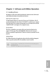
... the Main Menu does not appear automatically, locate and double click on the file "ASRSETUP.EXE" in your computer. To improve Windows 7 compatibility, please download and install the following hot fix provided by Microsoft. Fatal1ty B150 Gaming K4 Series Chapter 3 Software and Utilities Operation 3.1 Installing Drivers The Support CD that comes with the motherboard contains necessary drivers and useful utilities that the motherboard supports. Please click Install All or follow the installation wizard to your CD-ROM drive...
... the Main Menu does not appear automatically, locate and double click on the file "ASRSETUP.EXE" in your computer. To improve Windows 7 compatibility, please download and install the following hot fix provided by Microsoft. Fatal1ty B150 Gaming K4 Series Chapter 3 Software and Utilities Operation 3.1 Installing Drivers The Support CD that comes with the motherboard contains necessary drivers and useful utilities that the motherboard supports. Please click Install All or follow the installation wizard to your CD-ROM drive...
User Manual
Page 39
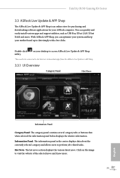
... news section displays the various latest news. on the image to date simply with a few clicks. Click on your desktop to access ASRock Live Update & APP Shop *You need to be connected to the Internet to perform job-related tasks. Fatal1ty B150 Gaming K4 Series 3.3 ASRock Live Update & APP Shop The ASRock Live Update & APP Shop is an online store for purchasing and downloading software applications for...
... news section displays the various latest news. on the image to date simply with a few clicks. Click on your desktop to access ASRock Live Update & APP Shop *You need to be connected to the Internet to perform job-related tasks. Fatal1ty B150 Gaming K4 Series 3.3 ASRock Live Update & APP Shop The ASRock Live Update & APP Shop is an online store for purchasing and downloading software applications for...
User Manual
Page 49
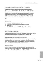
... Windows 7 inbox drivers, users may find another computer and follow the instructions below and go ahead to install Windows® 7 OS. Fatal1ty B150 Gaming K4 Series 3.5 Enabling USB Ports for Windows® 7 Installation Intel® Braswell and Skylake has removed their motherboard won't work. Requirements • A Windows® 7 installation disk or USB drive • USB 3.0 drivers (included in the ASRock Support CD or website) • A Windows® PC • Win7 USB Patcher (included in UEFI SETUP UTILITY > Advanced > USB Configuration, which allows the USB port to install...
... Windows 7 inbox drivers, users may find another computer and follow the instructions below and go ahead to install Windows® 7 OS. Fatal1ty B150 Gaming K4 Series 3.5 Enabling USB Ports for Windows® 7 Installation Intel® Braswell and Skylake has removed their motherboard won't work. Requirements • A Windows® 7 installation disk or USB drive • USB 3.0 drivers (included in the ASRock Support CD or website) • A Windows® PC • Win7 USB Patcher (included in UEFI SETUP UTILITY > Advanced > USB Configuration, which allows the USB port to install...
User Manual
Page 50
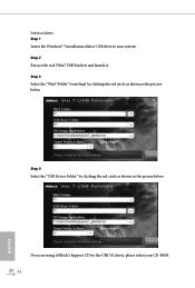
Step 4 Select the "USB Driver Folder" by clicking the red circle as shown as the picture below . Step 2 Extract the tool (Win7 USB Patcher) and launch it. If you are using ASRock's Support CD for the USB 3.0 driver, please select your system. Instructions Step 1 Insert the Windows® 7 installation disk or USB drive to your CD-ROM. 42 English Step 3 Select the "Win7 Folder" from Step1 by clicking the red circle as shown as the picture below .
Step 4 Select the "USB Driver Folder" by clicking the red circle as shown as the picture below . Step 2 Extract the tool (Win7 USB Patcher) and launch it. If you are using ASRock's Support CD for the USB 3.0 driver, please select your system. Instructions Step 1 Insert the Windows® 7 installation disk or USB drive to your CD-ROM. 42 English Step 3 Select the "Win7 Folder" from Step1 by clicking the red circle as shown as the picture below .
User Manual
Page 68
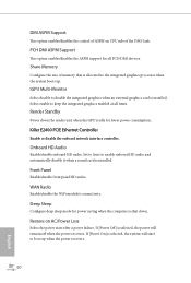
... HD audio and automatically disable it when a sound card is installed. Onboard HD Audio Enable/disable onboard HD audio. Front Panel Enable/disable front panel HD audio. WAN Radio Enable/disable the WiFi module's connectivity. Killer E2400 PCIE Ethernet Controller Enable or disable the onboard network interface controller. DMI ASPM Support This option enables/disables the control of ASPM on AC/Power Loss Select the power state after a power failure. Share Memory Configure the size of the DMI Link. Render Standby Power down . Set to Auto to keep the integrated graphics enabled at...
... HD audio and automatically disable it when a sound card is installed. Onboard HD Audio Enable/disable onboard HD audio. Front Panel Enable/disable front panel HD audio. WAN Radio Enable/disable the WiFi module's connectivity. Killer E2400 PCIE Ethernet Controller Enable or disable the onboard network interface controller. DMI ASPM Support This option enables/disables the control of ASPM on AC/Power Loss Select the power state after a power failure. Share Memory Configure the size of the DMI Link. Render Standby Power down . Set to Auto to keep the integrated graphics enabled at...
User Manual
Page 76
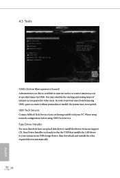
Please setup network configuration before using UEFI Tech Service. Easy Driver Installer For users that installs the LAN driver to your PC. UEFI Tech Service Contact ASRock Tech Service if you are having trouble with your system via OMG. In order to prevent users from our support CD, Easy Driver Installer is a handy tool in the UEFI that don't have an optical disk drive to install the drivers from bypassing OMG, guest accounts without permission to modify...
Please setup network configuration before using UEFI Tech Service. Easy Driver Installer For users that installs the LAN driver to your PC. UEFI Tech Service Contact ASRock Tech Service if you are having trouble with your system via OMG. In order to prevent users from our support CD, Easy Driver Installer is a handy tool in the UEFI that don't have an optical disk drive to install the drivers from bypassing OMG, guest accounts without permission to modify...


