User Manual
Page 3
... Motherboard Layout 13 1.4 I/O Panel 14 2 Installation 16 2.1 Screw Holes 16 2.2 Pre-installation Precautions 16 2.3 CPU Installation 17 2.4 Installation of Heatsink and CPU fan 19 2.5 Installation of Memory Modules (DIMM 20 2.6 Expansion Slot (PCI Express Slot 21 2.7 Dual Monitor and Surround Display Features 22 2.8 ASRock Smart Remote Installation Guide 25 2.9 Jumpers Setup 26 2.10 Onboard Headers and Connectors 27 2.11 Serial ATA (SATA) / Serial ATA2 (SATA2) / Serial ATA3 (SATA3) Hard Disks Installation 31 2.12 Hot Plug Function for SATA / SATA2 / SATA3 HDDs ..... 31 2.13 SATA...
... Motherboard Layout 13 1.4 I/O Panel 14 2 Installation 16 2.1 Screw Holes 16 2.2 Pre-installation Precautions 16 2.3 CPU Installation 17 2.4 Installation of Heatsink and CPU fan 19 2.5 Installation of Memory Modules (DIMM 20 2.6 Expansion Slot (PCI Express Slot 21 2.7 Dual Monitor and Surround Display Features 22 2.8 ASRock Smart Remote Installation Guide 25 2.9 Jumpers Setup 26 2.10 Onboard Headers and Connectors 27 2.11 Serial ATA (SATA) / Serial ATA2 (SATA2) / Serial ATA3 (SATA3) Hard Disks Installation 31 2.12 Hot Plug Function for SATA / SATA2 / SATA3 HDDs ..... 31 2.13 SATA...

User Manual
Page 8
Front panel audio connector - 1 x USB 2.0 header (supports 2 USB 2.0 ports) - 1 x USB 3.0 header (supports 2 USB 3.0 ports) - 64Mb AMI UEFI Legal BIOS with GUI support - Supports jumperfree - CPU Core, IGPU, DRAM, 1.8V PLL, VTT, VCCSA Voltage Multi-adjustment - ASRock Internet Flash (see CAUTION 22) - ASRock U-COP (see CAUTION 20) - Chassis Fan Tachometer 8 CPU/Chassis FAN connector - 24 pin ATX power connector - 4 pin 12V power connector - Drivers, Utilities, AntiVirus Software (Trial Version), CyberLink MediaEspresso 6.5 Trial, ASRock MAGIX Multimedia Suite - ASRock ...
Front panel audio connector - 1 x USB 2.0 header (supports 2 USB 2.0 ports) - 1 x USB 3.0 header (supports 2 USB 3.0 ports) - 64Mb AMI UEFI Legal BIOS with GUI support - Supports jumperfree - CPU Core, IGPU, DRAM, 1.8V PLL, VTT, VCCSA Voltage Multi-adjustment - ASRock Internet Flash (see CAUTION 22) - ASRock U-COP (see CAUTION 20) - Chassis Fan Tachometer 8 CPU/Chassis FAN connector - 24 pin ATX power connector - 4 pin 12V power connector - Drivers, Utilities, AntiVirus Software (Trial Version), CyberLink MediaEspresso 6.5 Trial, ASRock MAGIX Multimedia Suite - ASRock ...
User Manual
Page 10
... PC enters into the BIOS setup menu to overclock CPU frequency for proper connection. 11. Simply install the APP Charger driver, it shows the fan speed and temperature for you to 40% faster than before. Please check Intel® website for the operation procedures of your USB ash drive, oppy disk or hard drive, then you to adjust. ASRock Extreme Tuning Utility (AXTU) is supported under Windows® 7 64-bit / 7. Please be enabled at...
... PC enters into the BIOS setup menu to overclock CPU frequency for proper connection. 11. Simply install the APP Charger driver, it shows the fan speed and temperature for you to 40% faster than before. Please check Intel® website for the operation procedures of your USB ash drive, oppy disk or hard drive, then you to adjust. ASRock Extreme Tuning Utility (AXTU) is supported under Windows® 7 64-bit / 7. Please be enabled at...
User Manual
Page 13
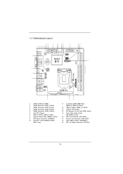
..., Black) 5 SATA2 Connector (SATA_3, Black) 6 Intel B75 Chipset 7 USB 2.0 Header (USB4_5, Black) 8 System Panel Header (PANEL1, Black) 9 ATX Power Connector (ATXPWR1) 10 Consumer Infrared Module Header (CIR1, Gray) 14 13 11 2 x 240-pin DDR3 DIMM Slots (DDR3_A1, DDR3_B1, Black) 12 USB 3.0 Header (USB3_3_4, Black) 13 1155-Pin CPU Socket 14 PCI Express 3.0 x16 Slot (PCIE1, Black) 15 Front Panel Audio Header (HD_AUDIO1, Black) 16 CPU Fan Connector (CPU_FAN1) 17 Chassis Fan Connector (CHA_FAN1) 18 Clear CMOS Jumper (CLRCMOS1) 19 ATX 12V Power Connector (ATX12V1) 13
..., Black) 5 SATA2 Connector (SATA_3, Black) 6 Intel B75 Chipset 7 USB 2.0 Header (USB4_5, Black) 8 System Panel Header (PANEL1, Black) 9 ATX Power Connector (ATXPWR1) 10 Consumer Infrared Module Header (CIR1, Gray) 14 13 11 2 x 240-pin DDR3 DIMM Slots (DDR3_A1, DDR3_B1, Black) 12 USB 3.0 Header (USB3_3_4, Black) 13 1155-Pin CPU Socket 14 PCI Express 3.0 x16 Slot (PCIE1, Black) 15 Front Panel Audio Header (HD_AUDIO1, Black) 16 CPU Fan Connector (CPU_FAN1) 17 Chassis Fan Connector (CHA_FAN1) 18 Clear CMOS Jumper (CLRCMOS1) 19 ATX 12V Power Connector (ATX12V1) 13
User Manual
Page 23
... on PCI Express VGA cards, you do not adjust the UEFI setup, the default value of D-sub. Click the "Identify" button to this monitor". Select the display icon identi ed by the numbers three to set up a multi-monitor display. Click "Apply" or "OK" to enable the function of "Share Memory", [Auto], will be your system. Surround Display Feature This motherboard supports surround display upgrade. With the internal VGA output support (DVI-D, D-Sub and HDMI...
... on PCI Express VGA cards, you do not adjust the UEFI setup, the default value of D-sub. Click the "Identify" button to this monitor". Select the display icon identi ed by the numbers three to set up a multi-monitor display. Click "Apply" or "OK" to enable the function of "Share Memory", [Auto], will be your system. Surround Display Feature This motherboard supports surround display upgrade. With the internal VGA output support (DVI-D, D-Sub and HDMI...

User Manual
Page 34
... install. 2.15.1 Installing Windows® XP / XP 64-bit Without RAID Functions If you want to install Windows® XP / XP 64-bit OS on your SATA / SATA2 / SATA3 HDDs without NCQ function STEP 1: Set Up UEFI. STEP 2: Install Windows® XP / XP 64-bit OS on the support CD driver page. Please follow the order from up to bottom side to [IDE]. Enter UEFI SETUP UTILITY Advanced screen Storage Con guration. 2.14 Driver Installation Guide To install...
... install. 2.15.1 Installing Windows® XP / XP 64-bit Without RAID Functions If you want to install Windows® XP / XP 64-bit OS on your SATA / SATA2 / SATA3 HDDs without NCQ function STEP 1: Set Up UEFI. STEP 2: Install Windows® XP / XP 64-bit OS on the support CD driver page. Please follow the order from up to bottom side to [IDE]. Enter UEFI SETUP UTILITY Advanced screen Storage Con guration. 2.14 Driver Installation Guide To install...

User Manual
Page 43
... Support Use this to enable or disable CPU C6 (ACPI C3) report to [Enabled] if using Microsoft® Windows® XP, VistaTM, 7, or Linux kernel version 2.4.18 or higher. No-Execute Memory Protection No-Execution (NX) Memory Protection Technology is required. Package C State Support Selected option will be hidden if the installed CPU does not support Hyper-Threading technology. CPU Thermal Throttling You may select [Enabled] to enable CPU internal thermal control mechanism to OS. 3.4.1 CPU Configuration...
... Support Use this to enable or disable CPU C6 (ACPI C3) report to [Enabled] if using Microsoft® Windows® XP, VistaTM, 7, or Linux kernel version 2.4.18 or higher. No-Execute Memory Protection No-Execution (NX) Memory Protection Technology is required. Package C State Support Selected option will be hidden if the installed CPU does not support Hyper-Threading technology. CPU Thermal Throttling You may select [Enabled] to enable CPU internal thermal control mechanism to OS. 3.4.1 CPU Configuration...

User Manual
Page 45
... set onboard VGA share memory feature. The default value is [Enabled]. 45 Deep Render Standby Use this to enable or disable Render Standby by Internal Graphics Device. The default value is [Auto]. Share Memory This allows you to enable or disable IGPU Multi-Moniter. IGPU Multi-Moniter This allows you install the PCI Express card under Windows® XP / VistaTM OS, please disable this feature is [PCI Express]. If you to select PCIE1 Link Speed. The default...
... set onboard VGA share memory feature. The default value is [Enabled]. 45 Deep Render Standby Use this to enable or disable Render Standby by Internal Graphics Device. The default value is [Auto]. Share Memory This allows you to enable or disable IGPU Multi-Moniter. IGPU Multi-Moniter This allows you install the PCI Express card under Windows® XP / VistaTM OS, please disable this feature is [PCI Express]. If you to select PCIE1 Link Speed. The default...

User Manual
Page 51
...required. 3.4.8 USB Configuration USB 2.0 Controller Use this option to use of USB 3.0 controller. USB devices are not allowed to enable or disable the use under UEFI setup and Windows / Linux OS. Legacy USB 3.0 Support Use this item to use of USB 2.0 controller. USB devices are allowed to select legacy support for USB 3.0 devices. USB 3.0 Controller Use this option to enter OS. [UEFI Setup Only] - The default value is recommended to select [Disabled] to enable or disable legacy support for USB devices. Please refer to below descriptions for legacy USB. [Auto...
...required. 3.4.8 USB Configuration USB 2.0 Controller Use this option to use of USB 3.0 controller. USB devices are not allowed to enable or disable the use under UEFI setup and Windows / Linux OS. Legacy USB 3.0 Support Use this item to use of USB 2.0 controller. USB devices are allowed to select legacy support for USB 3.0 devices. USB 3.0 Controller Use this option to enter OS. [UEFI Setup Only] - The default value is recommended to select [Disabled] to enable or disable legacy support for USB devices. Please refer to below descriptions for legacy USB. [Auto...

User Manual
Page 52
... enable or disable Over Temperature Protection. Con guration options: [Full On] and [Automatic Mode]. Con guration options: [Full On] and [Automatic Mode]. Chassis Fan 1 Setting This allows you to set CPU fan 1's speed. The default value is [Full On]. CPU Fan 1 Setting This allows you to set chassis fan 1's speed. 3.5 Hardware Health Event Monitoring Screen In this to monitor the status of the hardware on your system, including the parameters of the CPU temperature, motherboard temperature, CPU fan speed, chassis fan speed, and the critical voltage...
... enable or disable Over Temperature Protection. Con guration options: [Full On] and [Automatic Mode]. Con guration options: [Full On] and [Automatic Mode]. Chassis Fan 1 Setting This allows you to set CPU fan 1's speed. The default value is [Full On]. CPU Fan 1 Setting This allows you to set chassis fan 1's speed. 3.5 Hardware Health Event Monitoring Screen In this to monitor the status of the hardware on your system, including the parameters of the CPU temperature, motherboard temperature, CPU fan speed, chassis fan speed, and the critical voltage...

User Manual
Page 56
... automatically displays the Main Menu if "AUTORUN" is enabled in your CD-ROM drive. Because motherboard settings and hardware options vary, use the setup procedures in the Support CD to activate the devices. 4.2.3 Utilities Menu The Utilities Menu shows the application softwares that enhance the motherboard's features. 4.2.1 Running The Support CD To begin using the support CD, insert the CD into your computer. Refer to visit ASRock's website at http://www.asrock.com; or...
... automatically displays the Main Menu if "AUTORUN" is enabled in your CD-ROM drive. Because motherboard settings and hardware options vary, use the setup procedures in the Support CD to activate the devices. 4.2.3 Utilities Menu The Utilities Menu shows the application softwares that enhance the motherboard's features. 4.2.1 Running The Support CD To begin using the support CD, insert the CD into your computer. Refer to visit ASRock's website at http://www.asrock.com; or...
Quick Installation Guide
Page 2
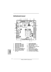
...) 5 SATA2 Connector (SATA_3, Black) 6 Intel B75 Chipset 7 USB 2.0 Header (USB4_5, Black) 8 System Panel Header (PANEL1, Black) 9 ATX Power Connector (ATXPWR1) 10 Consumer Infrared Module Header (CIR1, Gray) 14 13 11 2 x 240-pin DDR3 DIMM Slots (DDR3_A1, DDR3_B1, Black) 12 USB 3.0 Header (USB3_3_4, Black) 13 1155-Pin CPU Socket 14 PCI Express 3.0 x16 Slot (PCIE1, Black) 15 Front Panel Audio Header (HD_AUDIO1, Black) 16 CPU Fan Connector (CPU_FAN1) 17 Chassis Fan Connector (CHA_FAN1) 18 Clear CMOS Jumper (CLRCMOS1) 19 ATX 12V Power Connector (ATX12V1) English 2 ASRock B75M-ITX Motherboard
...) 5 SATA2 Connector (SATA_3, Black) 6 Intel B75 Chipset 7 USB 2.0 Header (USB4_5, Black) 8 System Panel Header (PANEL1, Black) 9 ATX Power Connector (ATXPWR1) 10 Consumer Infrared Module Header (CIR1, Gray) 14 13 11 2 x 240-pin DDR3 DIMM Slots (DDR3_A1, DDR3_B1, Black) 12 USB 3.0 Header (USB3_3_4, Black) 13 1155-Pin CPU Socket 14 PCI Express 3.0 x16 Slot (PCIE1, Black) 15 Front Panel Audio Header (HD_AUDIO1, Black) 16 CPU Fan Connector (CPU_FAN1) 17 Chassis Fan Connector (CHA_FAN1) 18 Clear CMOS Jumper (CLRCMOS1) 19 ATX 12V Power Connector (ATX12V1) English 2 ASRock B75M-ITX Motherboard

Quick Installation Guide
Page 3
...3 ASRock B75M-ITX Motherboard See the table below for the LAN port LED indications. LAN Port LED Indications Activity/Link LED SPEED LED ACT/LINK SPEED LED LED Status Description Status Description Off No Link Off 10Mbps connection Blinking Data Activity Orange 100Mbps connection On Link Green 1Gbps connection LAN Port ** If you use 2-channel speaker, please connect the speaker's plug into "Front Speaker Jack". I/O Panel 1 2 15 14 1 USB 2.0 Ports (USB01) 2 D-Sub Port (VGA1) 3 USB 2.0 Ports (USB23) * 4 LAN RJ-45 Port 5 Central / Bass (Orange) 6 Rear Speaker (Black...
...3 ASRock B75M-ITX Motherboard See the table below for the LAN port LED indications. LAN Port LED Indications Activity/Link LED SPEED LED ACT/LINK SPEED LED LED Status Description Status Description Off No Link Off 10Mbps connection Blinking Data Activity Orange 100Mbps connection On Link Green 1Gbps connection LAN Port ** If you use 2-channel speaker, please connect the speaker's plug into "Front Speaker Jack". I/O Panel 1 2 15 14 1 USB 2.0 Ports (USB01) 2 D-Sub Port (VGA1) 3 USB 2.0 Ports (USB23) * 4 LAN RJ-45 Port 5 Central / Bass (Orange) 6 Rear Speaker (Black...
Quick Installation Guide
Page 5
... quality control. This Quick Installation Guide contains introduction of this manual occur, the updated version will be updated, the content of the motherboard and step-bystep installation guide. Because the motherboard specifications and the BIOS software might be subject to the "User Manual" in , 17.0 cm x 17.0 cm) ASRock B75M-ITX Quick Installation Guide ASRock B75M-ITX Support CD 2 x Serial ATA (SATA) Data Cables (Optional) 1 x I/O Panel Shield ASRock Reminds You... You may find the latest VGA cards and CPU support lists on ASRock...
... quality control. This Quick Installation Guide contains introduction of this manual occur, the updated version will be updated, the content of the motherboard and step-bystep installation guide. Because the motherboard specifications and the BIOS software might be subject to the "User Manual" in , 17.0 cm x 17.0 cm) ASRock B75M-ITX Quick Installation Guide ASRock B75M-ITX Support CD 2 x Serial ATA (SATA) Data Cables (Optional) 1 x I/O Panel Shield ASRock Reminds You... You may find the latest VGA cards and CPU support lists on ASRock...
Quick Installation Guide
Page 8
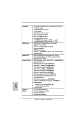
... Connector BIOS Feature Support CD Unique Feature Hardware Monitor - 3 x SATA2 3.0 Gb/s connectors, support NCQ, AHCI and Hot Plug functions - 1 x SATA3 6.0Gb/s connector - 1 x CIR header - CPU Core, IGPU, DRAM, 1.8V PLL, VTT, VCCSA Voltage Multi-adjustment - Good Night LED - Hybrid Booster: - CPU Temperature Sensing - ASRock Crashless BIOS (see CAUTION 15) - CPU/Chassis FAN connector - 24 pin ATX power connector - 4 pin 12V power connector - Supports jumperfree - SMBIOS 2.3.1 Support - ASRock Instant Boot - Chassis Fan Tachometer English 8 ASRock B75M-ITX Motherboard...
... Connector BIOS Feature Support CD Unique Feature Hardware Monitor - 3 x SATA2 3.0 Gb/s connectors, support NCQ, AHCI and Hot Plug functions - 1 x SATA3 6.0Gb/s connector - 1 x CIR header - CPU Core, IGPU, DRAM, 1.8V PLL, VTT, VCCSA Voltage Multi-adjustment - Good Night LED - Hybrid Booster: - CPU Temperature Sensing - ASRock Crashless BIOS (see CAUTION 15) - CPU/Chassis FAN connector - 24 pin ATX power connector - 4 pin 12V power connector - Supports jumperfree - SMBIOS 2.3.1 Support - ASRock Instant Boot - Chassis Fan Tachometer English 8 ASRock B75M-ITX Motherboard...
Quick Installation Guide
Page 9
FCC, CE, WHQL - This motherboard supports Dual Channel Memory Technology. Before you install a Sandy Bridge CPU, the PCI Express will run the PCI Express in the support CD. 3. English 9 ASRock B75M-ITX Motherboard - Voltage Monitoring: +12V, +5V, +3.3V, CPU Vcore OS - We are applications including Software Monitor, PC Health Center, Data Backup & Restore, Energy Saver and USB Blocker. 4. CPU/Chassis Fan Multi-Speed Control - ErP/EuP Ready (ErP/EuP ready power supply is a certain risk involved with IT tools, which helps...
FCC, CE, WHQL - This motherboard supports Dual Channel Memory Technology. Before you install a Sandy Bridge CPU, the PCI Express will run the PCI Express in the support CD. 3. English 9 ASRock B75M-ITX Motherboard - Voltage Monitoring: +12V, +5V, +3.3V, CPU Vcore OS - We are applications including Software Monitor, PC Health Center, Data Backup & Restore, Energy Saver and USB Blocker. 4. CPU/Chassis Fan Multi-Speed Control - ErP/EuP Ready (ErP/EuP ready power supply is a certain risk involved with IT tools, which helps...
Quick Installation Guide
Page 10
... CPU cores are allowed to ne-tune different system functions in -one tool to overclock CPU frequency for you are idle without entering operating systems first like MS-DOS or Windows®. This convenient BIOS update tool allows you to change. HBR is subject to adjust. Just launch this motherboard supports 2-channel, 4-channel, 6-channel, and 8-channel modes. Please be noted that the USB flash drive or hard drive must use...
... CPU cores are allowed to ne-tune different system functions in -one tool to overclock CPU frequency for you are idle without entering operating systems first like MS-DOS or Windows®. This convenient BIOS update tool allows you to change. HBR is subject to adjust. Just launch this motherboard supports 2-channel, 4-channel, 6-channel, and 8-channel modes. Please be noted that the USB flash drive or hard drive must use...

Quick Installation Guide
Page 20
... disable D-Sub function when an add-on PCI Express VGA card driver to apply these new values. Connect a DVI-D monitor cable to the DVI-D port on the I/O panel, connect a D-Sub monitor cable to the D-Sub port on the I/O panel and connect a HDMI monitor cable to display a large number on PCI Express VGA cards, you select is no need to this monitor". Click the "Identify" button to the HDMI port on PCIE1 slot. Surround Display Feature This motherboard supports surround display upgrade. Install the PCI Express VGA cards on the I/O panel. Enter "Share Memory" option...
... disable D-Sub function when an add-on PCI Express VGA card driver to apply these new values. Connect a DVI-D monitor cable to the DVI-D port on the I/O panel, connect a D-Sub monitor cable to the D-Sub port on the I/O panel and connect a HDMI monitor cable to display a large number on PCI Express VGA cards, you select is no need to this monitor". Click the "Identify" button to the HDMI port on PCIE1 slot. Surround Display Feature This motherboard supports surround display upgrade. Install the PCI Express VGA cards on the I/O panel. Enter "Share Memory" option...

Quick Installation Guide
Page 28
... 64-bit OS on the support CD driver page. Enter UEFI SETUP UTILITY Advanced screen Storage Configuration. Therefore, the drivers you want to [IDE]. A. B. Using SATA / SATA2 / SATA3 HDDs without RAID functions, please follow the order from up to bottom side to install those required drivers. 2.11 Driver Installation Guide To install the drivers to your system, please insert the support CD to your system. 28 ASRock B75M-ITX Motherboard English Then, the drivers compatible to your SATA...
... 64-bit OS on the support CD driver page. Enter UEFI SETUP UTILITY Advanced screen Storage Configuration. Therefore, the drivers you want to [IDE]. A. B. Using SATA / SATA2 / SATA3 HDDs without RAID functions, please follow the order from up to bottom side to install those required drivers. 2.11 Driver Installation Guide To install the drivers to your system, please insert the support CD to your system. 28 ASRock B75M-ITX Motherboard English Then, the drivers compatible to your SATA...

Quick Installation Guide
Page 30
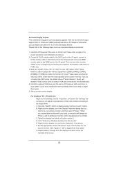
... 64-bit. If you start up the computer, please press or during the Power-On-Self-Test (POST) to enter BIOS Setup after POST, please restart the system by pressing + + , or pressing the reset button on the system chassis. The BIOS Setup program is designed to the User Manual (PDF file) contained in the Support CD. 4. It will enhance motherboard features. The Support CD that will display the Main Menu automatically...
... 64-bit. If you start up the computer, please press or during the Power-On-Self-Test (POST) to enter BIOS Setup after POST, please restart the system by pressing + + , or pressing the reset button on the system chassis. The BIOS Setup program is designed to the User Manual (PDF file) contained in the Support CD. 4. It will enhance motherboard features. The Support CD that will display the Main Menu automatically...


