
User Manual
Page 10
... the USB flash drive or hard drive must use SmartView feature, please make sure your OS version is Windows® 7 / 7 64 bit / VistaTM / VistaTM 64 bit, and your PC and apple devices via Bluetooth or WiFi networks, then you can start page for you can press key during the POST or press key to BIOS setup menu to RAM (S3), hibernation mode (S4) or power off (S5). Connecting your browser version is the smart start experiencing...
... the USB flash drive or hard drive must use SmartView feature, please make sure your OS version is Windows® 7 / 7 64 bit / VistaTM / VistaTM 64 bit, and your PC and apple devices via Bluetooth or WiFi networks, then you can start page for you can press key during the POST or press key to BIOS setup menu to RAM (S3), hibernation mode (S4) or power off (S5). Connecting your browser version is the smart start experiencing...
User Manual
Page 12
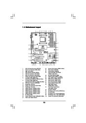
... 23 22 21 20 10 11 12 13 14 15 16 17 18 19 1 ATX 12V Power Connector (ATX12V1) 22 System Panel Header (PANEL1, White) 2 Power Fan Connector (PWR_FAN1) 23 Reset Switch (RSTBTN) 3 AM3+ CPU Socket 24 Power Switch (PWRBTN) 4 CPU Heatsink Retention Module 25 Front Panel IEEE 1394 Header 5 CPU Fan Connector (CPU_FAN2) (FRONT_1394, White) 6 CPU Fan Connector (CPU_FAN1) 26 SPI Flash Memory (32Mb) 7 Chassis Fan Connector (CHA_FAN2) 27 USB 2.0 Header (USB10_11, Blue) 8 2 x 240-pin DDR3 DIMM Slots 28 Clear CMOS Jumper (CLRCMOS1) (Dual Channel A: DDR3_A1, DDR3_B1;
... 23 22 21 20 10 11 12 13 14 15 16 17 18 19 1 ATX 12V Power Connector (ATX12V1) 22 System Panel Header (PANEL1, White) 2 Power Fan Connector (PWR_FAN1) 23 Reset Switch (RSTBTN) 3 AM3+ CPU Socket 24 Power Switch (PWRBTN) 4 CPU Heatsink Retention Module 25 Front Panel IEEE 1394 Header 5 CPU Fan Connector (CPU_FAN2) (FRONT_1394, White) 6 CPU Fan Connector (CPU_FAN1) 26 SPI Flash Memory (32Mb) 7 Chassis Fan Connector (CHA_FAN2) 27 USB 2.0 Header (USB10_11, Blue) 8 2 x 240-pin DDR3 DIMM Slots 28 Clear CMOS Jumper (CLRCMOS1) (Dual Channel A: DDR3_A1, DDR3_B1;

User Manual
Page 20
... the internal VGA output support (DVI-D, D-Sub and HDMI), you can easily enjoy the benefits of dual monitor feature without installing any add-on VGA card to use dual monitor function on the I/O panel. Then you can start to this motherboard. 1. If you can drive same or different display contents. To enable dual monitor feature, please follow the below steps: 1. 2.5 Dual Monitor and Surround Display Features Dual Monitor Feature This motherboard supports dual monitor feature. This motherboard also provides independent display controllers...
... the internal VGA output support (DVI-D, D-Sub and HDMI), you can easily enjoy the benefits of dual monitor feature without installing any add-on VGA card to use dual monitor function on the I/O panel. Then you can start to this motherboard. 1. If you can drive same or different display contents. To enable dual monitor feature, please follow the below steps: 1. 2.5 Dual Monitor and Surround Display Features Dual Monitor Feature This motherboard supports dual monitor feature. This motherboard also provides independent display controllers...

User Manual
Page 21
...-click the display icon in the Display Properties dialog that you have installed the drivers already, there is inserted to your system. Set up a surround display environment: 1. E. With the internal VGA output support (DVI-D, D-Sub and HDMI) and external add-on PCIE2 and PCIE3 slots. 3. Click "Extend my Windows desktop onto this motherboard. 4. Surround Display Feature This motherboard supports surround display upgrade. Install the ATITM PCI Express VGA cards on PCI Express VGA card driver to this monitor". Install the onboard VGA driver and...
...-click the display icon in the Display Properties dialog that you have installed the drivers already, there is inserted to your system. Set up a surround display environment: 1. E. With the internal VGA output support (DVI-D, D-Sub and HDMI) and external add-on PCIE2 and PCIE3 slots. 3. Click "Extend my Windows desktop onto this motherboard. 4. Surround Display Feature This motherboard supports surround display upgrade. Install the ATITM PCI Express VGA cards on PCI Express VGA card driver to this monitor". Install the onboard VGA driver and...

User Manual
Page 23
... series graphics processor and a motherboard based on an AMD 880G integrated chipset, all operating in your system. Step 2. Connect the monitor cable to [Enabled]. Then set the option "Surround View" to the correspondent connector on the PCI Express graphics card on your system for ATITM Hybrid CrossFireXTM. Please remove the ATITM driver if you will find "ATI Catalyst Control Center" on PCIE2 slot. Restart your system. Press to section "Expansion Slots". Enter "Advanced" screen, and enter...
... series graphics processor and a motherboard based on an AMD 880G integrated chipset, all operating in your system. Step 2. Connect the monitor cable to [Enabled]. Then set the option "Surround View" to the correspondent connector on the PCI Express graphics card on your system for ATITM Hybrid CrossFireXTM. Please remove the ATITM driver if you will find "ATI Catalyst Control Center" on PCIE2 slot. Restart your system. Press to section "Expansion Slots". Enter "Advanced" screen, and enter...
User Manual
Page 27
... optional download. The Catalyst Uninstaller is no need to installation. Step 4. Then you have Microsoft .NET Framework installed prior to uninstall any VGA driver installed in your system. Click "View", select "CrossFireXTM", and then check the item "Enable CrossFireXTM". 2.7.2 Driver Installation and Setup Step 1. Step 5. Install the VGA card drivers to your Windows® taskbar. Power on your system. Step 2. We recommend using this utility to downloading and installing the CATALYST Control...
... optional download. The Catalyst Uninstaller is no need to installation. Step 4. Then you have Microsoft .NET Framework installed prior to uninstall any VGA driver installed in your system. Click "View", select "CrossFireXTM", and then check the item "Enable CrossFireXTM". 2.7.2 Driver Installation and Setup Step 1. Step 5. Install the VGA card drivers to your Windows® taskbar. Power on your system. Step 2. We recommend using this utility to downloading and installing the CATALYST Control...

User Manual
Page 36
...used to provide code information, which makes troubleshooting even easier. Boot Strap Processor (BSP) selection CPU post-memory initialization. Memory presence detection Memory initialization. Configuring memory Memory initialization (other) Reserved for future AMI SEC error codes Microcode not found Microcode not loaded PEI Core is started Pre-memory CPU initialization is started Pre-memory CPU initialization (CPU module specific) Pre-memory CPU initialization (CPU module specific) Pre-memory CPU initialization (CPU module specific) Pre-memory North Bridge initialization is started CPU...
...used to provide code information, which makes troubleshooting even easier. Boot Strap Processor (BSP) selection CPU post-memory initialization. Memory presence detection Memory initialization. Configuring memory Memory initialization (other) Reserved for future AMI SEC error codes Microcode not found Microcode not loaded PEI Core is started Pre-memory CPU initialization is started Pre-memory CPU initialization (CPU module specific) Pre-memory CPU initialization (CPU module specific) Pre-memory CPU initialization (CPU module specific) Pre-memory North Bridge initialization is started CPU...
User Manual
Page 41
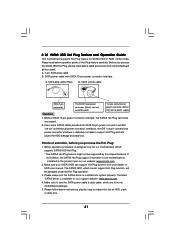
... not able to use the SATA power cable & data cable, which are from our motherboard package. 5. Below operation procedure is indicated in RAID / AHCI mode. SATA power cable with SATA 15-pin power connector interface A. A. 7-pin SATA data cable B. Without SATA 15-pin power connector interface, the SATA3 Hot Plug cannot be supported by step to power supply Caution 1. The latest SATA3 driver is installed into system properly. Make sure your dealer or HDD user manual. Please read below operation guide of attention...
... not able to use the SATA power cable & data cable, which are from our motherboard package. 5. Below operation procedure is indicated in RAID / AHCI mode. SATA power cable with SATA 15-pin power connector interface A. A. 7-pin SATA data cable B. Without SATA 15-pin power connector interface, the SATA3 Hot Plug cannot be supported by step to power supply Caution 1. The latest SATA3 driver is installed into system properly. Make sure your dealer or HDD user manual. Please read below operation guide of attention...
User Manual
Page 43
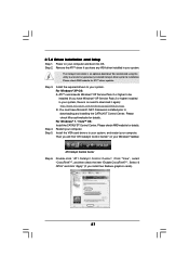
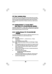
A. Enter UEFI SETUP UTILITY Advanced screen Storage Configuration. ROM as the boot device. Insert the ASRock Support CD into the floppy drive, and press any key. Please follow the order from up , press key, and then a window for boot devices selection appears. Set the "SATA Mode" option to your optical drive first. STEP 2: Make a SATA3 Driver Diskette. (Please use USB floppy or floppy disk.) A. B. During POST at the beginning of system boot-up to bottom side to install those required drivers. D. Then you will see...
A. Enter UEFI SETUP UTILITY Advanced screen Storage Configuration. ROM as the boot device. Insert the ASRock Support CD into the floppy drive, and press any key. Please follow the order from up , press key, and then a window for boot devices selection appears. Set the "SATA Mode" option to your optical drive first. STEP 2: Make a SATA3 Driver Diskette. (Please use USB floppy or floppy disk.) A. B. During POST at the beginning of system boot-up to bottom side to install those required drivers. D. Then you will see...
User Manual
Page 57
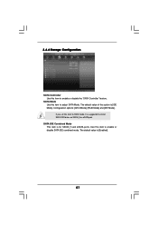
Use this item to enable or disable the "SATA Controller" feature. The default value is for SATA3_5 and eSATA ports. 3.4.4 Storage Configuration SATA Controller Use this item to enable or disable SATA IDE combined mode. Configuration options: [AHCI Mode], [RAID Mode] and [IDE Mode]. SATA IDE Combined Mode This item is [Enabled]. 57 SATA Mode Use this item to RAID mode, it is [IDE Mode]. If you set this item to install SATA ODD driver on SATA3_5 or eSATA port. The default value of this option is suggested to adjust SATA Mode.
Use this item to enable or disable the "SATA Controller" feature. The default value is for SATA3_5 and eSATA ports. 3.4.4 Storage Configuration SATA Controller Use this item to enable or disable SATA IDE combined mode. Configuration options: [AHCI Mode], [RAID Mode] and [IDE Mode]. SATA IDE Combined Mode This item is [Enabled]. 57 SATA Mode Use this item to RAID mode, it is [IDE Mode]. If you set this item to install SATA ODD driver on SATA3_5 or eSATA port. The default value of this option is suggested to adjust SATA Mode.

User Manual
Page 60
... USB compatibility issue, it is recommended to select [Disabled] to enable or disable legacy support for USB devices. Legacy USB 3.0 Support Use this option to enter OS. [UEFI Setup Only] - Enables legacy support if USB devices are four confi guration options: [Enabled], [Auto], [Disabled] and [UEFI Setup Only]. The default value is [Enabled]. Please refer to select legacy support for USB 3.0 devices. USB devices are allowed to use of these four options: [Enabled] - There are connected. [Disabled] - Enables support for the details of USB 2.0 controller. USB devices...
... USB compatibility issue, it is recommended to select [Disabled] to enable or disable legacy support for USB devices. Legacy USB 3.0 Support Use this option to enter OS. [UEFI Setup Only] - Enables legacy support if USB devices are four confi guration options: [Enabled], [Auto], [Disabled] and [UEFI Setup Only]. The default value is [Enabled]. Please refer to select legacy support for USB 3.0 devices. USB devices are allowed to use of these four options: [Enabled] - There are connected. [Disabled] - Enables support for the details of USB 2.0 controller. USB devices...
User Manual
Page 65
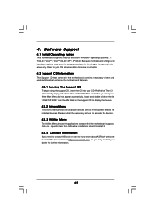
... for further information. 65 Because motherboard settings and hardware options vary, use the setup procedures in your CD-ROM drive. If the Main Menu did not appear automatically, locate and double click on a specific item then follow the installation wizard to activate the devices. 4.2.3 Utilities Menu The Utilities Menu shows the applications software that enhance the motherboard features. 4.2.1 Running The Support CD To begin using the support CD, insert the CD into...
... for further information. 65 Because motherboard settings and hardware options vary, use the setup procedures in your CD-ROM drive. If the Main Menu did not appear automatically, locate and double click on a specific item then follow the installation wizard to activate the devices. 4.2.3 Utilities Menu The Utilities Menu shows the applications software that enhance the motherboard features. 4.2.1 Running The Support CD To begin using the support CD, insert the CD into...
Quick Installation Guide
Page 2
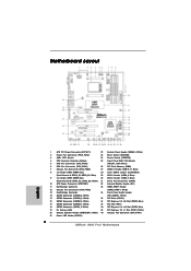
...21 Power LED Header (PLED1) 2 ASRock 880G Pro3 Motherboard Motherboard Layout English 1 ATX 12V Power Connector (ATX12V1) 22 System Panel Header (PANEL1, White) 2 Power Fan Connector (PWR_FAN1) 23 Reset Switch (RSTBTN) 3 AM3+ CPU Socket 24 Power Switch (PWRBTN) 4 CPU Heatsink Retention Module 25 Front Panel IEEE 1394 Header 5 CPU Fan Connector (CPU_FAN2) (FRONT_1394, White) 6 CPU Fan Connector (CPU_FAN1) 26 SPI Flash Memory (32Mb) 7 Chassis Fan Connector (CHA_FAN2) 27 USB 2.0 Header (USB10_11, Blue) 8 2 x 240-pin DDR3 DIMM Slots 28 Clear CMOS Jumper (CLRCMOS1) (Dual Channel...
...21 Power LED Header (PLED1) 2 ASRock 880G Pro3 Motherboard Motherboard Layout English 1 ATX 12V Power Connector (ATX12V1) 22 System Panel Header (PANEL1, White) 2 Power Fan Connector (PWR_FAN1) 23 Reset Switch (RSTBTN) 3 AM3+ CPU Socket 24 Power Switch (PWRBTN) 4 CPU Heatsink Retention Module 25 Front Panel IEEE 1394 Header 5 CPU Fan Connector (CPU_FAN2) (FRONT_1394, White) 6 CPU Fan Connector (CPU_FAN1) 26 SPI Flash Memory (32Mb) 7 Chassis Fan Connector (CHA_FAN2) 27 USB 2.0 Header (USB10_11, Blue) 8 2 x 240-pin DDR3 DIMM Slots 28 Clear CMOS Jumper (CLRCMOS1) (Dual Channel...

Quick Installation Guide
Page 17
... installed onboard VGA driver from Blu-ray (BD) or HD-DVD disc, the content will be displayed only in one of the two monitors instead of them is enabled, the other one will be disabled. 2. When one of both monitors. 17 ASRock 880G Pro3 Motherboard English DVI-D and HDMI ports cannot function at the same time. 2.5 Dual Monitor and Surround Display Features Dual Monitor Feature This motherboard supports dual monitor feature. This motherboard also provides independent display controllers...
... installed onboard VGA driver from Blu-ray (BD) or HD-DVD disc, the content will be displayed only in one of the two monitors instead of them is enabled, the other one will be disabled. 2. When one of both monitors. 17 ASRock 880G Pro3 Motherboard English DVI-D and HDMI ports cannot function at the same time. 2.5 Dual Monitor and Surround Display Features Dual Monitor Feature This motherboard supports dual monitor feature. This motherboard also provides independent display controllers...

Quick Installation Guide
Page 18
... the display icon and select "Attached", if necessary. If you can adjust the parameters of the system memory. G. Install the ATITM PCI Express VGA cards on VGA card is no need to enter UEFI setup. Boot your primary monitor, and then select "Primary". D. Click the "Identify" button to your card, one , two, three, four, five and six. 18 ASRock 880G Pro3 Motherboard English C. F. With the internal VGA output support (DVI-D, D-Sub and HDMI) and...
... the display icon and select "Attached", if necessary. If you can adjust the parameters of the system memory. G. Install the ATITM PCI Express VGA cards on VGA card is no need to enter UEFI setup. Boot your primary monitor, and then select "Primary". D. Click the "Identify" button to your card, one , two, three, four, five and six. 18 ASRock 880G Pro3 Motherboard English C. F. With the internal VGA output support (DVI-D, D-Sub and HDMI) and...
Quick Installation Guide
Page 24
... required drivers to downloading and installing the CATALYST Control Center. Click "View", select "CrossFireXTM", and then check the item "Enable CrossFireXTM". English 24 ASRock 880G Pro3 Motherboard Step 3. Install the VGA card drivers to installation. You must have Windows® XP Service Pack 2 or higher installed in your system. Step 5. Restart your computer and boot into OS. ATI Catalyst Control Center Step 6. Please check AMD website for ATITM driver updates. ATITM recommends Windows...
... required drivers to downloading and installing the CATALYST Control Center. Click "View", select "CrossFireXTM", and then check the item "Enable CrossFireXTM". English 24 ASRock 880G Pro3 Motherboard Step 3. Install the VGA card drivers to installation. You must have Windows® XP Service Pack 2 or higher installed in your system. Step 5. Restart your computer and boot into OS. ATI Catalyst Control Center Step 6. Please check AMD website for ATITM driver updates. ATITM recommends Windows...

Quick Installation Guide
Page 33
... is used Power on. System Management Mode (SMM) initialization 33 ASRock 880G Pro3 Motherboard English Serial Presence Detect (SPD) data reading Memory initialization. 2.11 Dr. Debug Dr. Debug is started Pre-memory South Bridge initialization (South Bridge module specific) Pre-memory South Bridge initialization (South Bridge module specific) Pre-memory South Bridge initialization (South Bridge module specific) OEM pre-memory initialization codes Memory initialization. Application Processor(s) (AP) initialization CPU post-memory initialization. Boot Strap Processor...
... is used Power on. System Management Mode (SMM) initialization 33 ASRock 880G Pro3 Motherboard English Serial Presence Detect (SPD) data reading Memory initialization. 2.11 Dr. Debug Dr. Debug is started Pre-memory South Bridge initialization (South Bridge module specific) Pre-memory South Bridge initialization (South Bridge module specific) Pre-memory South Bridge initialization (South Bridge module specific) OEM pre-memory initialization codes Memory initialization. Application Processor(s) (AP) initialization CPU post-memory initialization. Boot Strap Processor...
RAID Installation Guide
Page 4
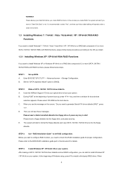
... part in this RAID installation guide for boot devices selection appears. D. WARNING!! Enter BIOS SETUP UTILITY → Advanced screen →Storage Configuration. Set the "SATA Operation Mode" option to set RAID configuration, you can start to format the floppy diskette and copy SATA / SATAII / SATA3 drivers into your optical drive to generate Serial ATA driver diskette [YN]?", press . At the beginning of 2 or more SATA / SATAII / SATA3 HDDs with RAID functions, please follow below steps. STEP 3: Use "RAID Installation Guide" to [RAID]. Insert the ASRock Support...
... part in this RAID installation guide for boot devices selection appears. D. WARNING!! Enter BIOS SETUP UTILITY → Advanced screen →Storage Configuration. Set the "SATA Operation Mode" option to set RAID configuration, you can start to format the floppy diskette and copy SATA / SATAII / SATA3 drivers into your optical drive to generate Serial ATA driver diskette [YN]?", press . At the beginning of 2 or more SATA / SATAII / SATA3 HDDs with RAID functions, please follow below steps. STEP 3: Use "RAID Installation Guide" to [RAID]. Insert the ASRock Support...
RAID Installation Guide
Page 5
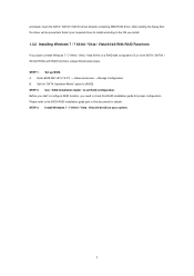
... After reading the floppy disk, the driver will be presented. B. STEP 3: Install Windows 7 / 7 64-bit / Vista / Vista 64-bit OS on a RAID disk composed of 2 or more SATA / SATAII / SATA3 HDDs with RAID functions, please follow below steps. STEP 2: Use "RAID Installation Guide" to [RAID]. prompted, insert the SATA / SATAII / SATA3 driver diskette containing AMD RAID driver. Enter BIOS SETUP UTILITY → Advanced screen →Storage Configuration. A. Please refer to check this document for proper configuration. Set the "SATA Operation Mode" option to set RAID configuration.
... After reading the floppy disk, the driver will be presented. B. STEP 3: Install Windows 7 / 7 64-bit / Vista / Vista 64-bit OS on a RAID disk composed of 2 or more SATA / SATAII / SATA3 HDDs with RAID functions, please follow below steps. STEP 2: Use "RAID Installation Guide" to [RAID]. prompted, insert the SATA / SATAII / SATA3 driver diskette containing AMD RAID driver. Enter BIOS SETUP UTILITY → Advanced screen →Storage Configuration. A. Please refer to check this document for proper configuration. Set the "SATA Operation Mode" option to set RAID configuration.
RAID Installation Guide
Page 10
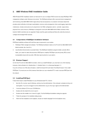
... first installation screen appears, choose an installer language from the dropdown menu. 10 RAIDXpert RAID management software: The RAIDXpert software installs on your system. 2.2 Browser Support On the Host PC with AMD SB850 SATA RAID controllers. You must have one of the above on your CD-ROM drive. 3. Double-click the Installer icon to configure RAID functions by using RAIDXpert RAID management software under the same directory where RAIDXpert is an instruction...
... first installation screen appears, choose an installer language from the dropdown menu. 10 RAIDXpert RAID management software: The RAIDXpert software installs on your system. 2.2 Browser Support On the Host PC with AMD SB850 SATA RAID controllers. You must have one of the above on your CD-ROM drive. 3. Double-click the Installer icon to configure RAID functions by using RAIDXpert RAID management software under the same directory where RAIDXpert is an instruction...

