MCXSP10 Manual
Page 3
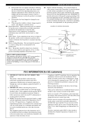
... cable. This product, when installed as an improper adjustment of interference, which can not locate the appropriate retailer, please contact Yamaha Electronics Corp., U.S.A. 6660 Orangethorpe Ave, Buena Park, CA 90620. This equipment generates/uses radio frequencies and, if not installed... the problem by the manufacturer. 23 Heat - IMPORTANT SAFETY INSTRUCTIONS 24 Outdoor Antenna Grounding - NATIONAL ELECTRICAL CODE ANTENNA LEAD IN WIRE ANTENNA DISCHARGE UNIT (NEC SECTION 810-20) GROUNDING CONDUCTORS (NEC SECTION 810-21) GROUND CLAMPS POWER SERVICE GROUNDING ELECTRODE SYSTEM (...
... cable. This product, when installed as an improper adjustment of interference, which can not locate the appropriate retailer, please contact Yamaha Electronics Corp., U.S.A. 6660 Orangethorpe Ave, Buena Park, CA 90620. This equipment generates/uses radio frequencies and, if not installed... the problem by the manufacturer. 23 Heat - IMPORTANT SAFETY INSTRUCTIONS 24 Outdoor Antenna Grounding - NATIONAL ELECTRICAL CODE ANTENNA LEAD IN WIRE ANTENNA DISCHARGE UNIT (NEC SECTION 810-20) GROUNDING CONDUCTORS (NEC SECTION 810-21) GROUND CLAMPS POWER SERVICE GROUNDING ELECTRODE SYSTEM (...
MCXSP10 Manual
Page 17
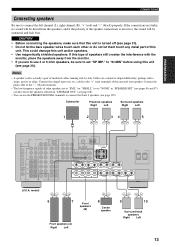
... the monitor. • If you are directed to the speakers selected in "LFE/BASS OUT" (see page 31). • Do not let the bare speaker wires touch each other speakers set "SP IMP." This could damage this unit (see page 105). Cables are colored or shaped differently, perhaps with the monitor...
... the monitor. • If you are directed to the speakers selected in "LFE/BASS OUT" (see page 31). • Do not let the bare speaker wires touch each other speakers set "SP IMP." This could damage this unit (see page 105). Cables are colored or shaped differently, perhaps with the monitor...
MCXSP10 Manual
Page 19
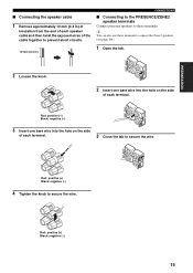
... ■ Connecting the speaker cable 1 Remove approximately 10 mm (0.4 in) of insulation from the end of each speaker cable and then twist the exposed wires of the cable together to prevent short circuits. 10 mm (0.4 in) CONNECTIONS ■ Connecting to the PRESENCE/ZONE2 speaker terminals Connect presence speakers to these ...terminals to connect the Zone 2 speakers (see page 104). 1 Open the tab. 2 Loosen the knob. 2 Insert one bare wire into the hole on the side of each terminal. 3 Close the tab to secure the...
... ■ Connecting the speaker cable 1 Remove approximately 10 mm (0.4 in) of insulation from the end of each speaker cable and then twist the exposed wires of the cable together to prevent short circuits. 10 mm (0.4 in) CONNECTIONS ■ Connecting to the PRESENCE/ZONE2 speaker terminals Connect presence speakers to these ...terminals to connect the Zone 2 speakers (see page 104). 1 Open the tab. 2 Loosen the knob. 2 Insert one bare wire into the hole on the side of each terminal. 3 Close the tab to secure the...
MCXSP10 Manual
Page 21
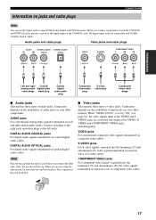
... audio cables. COMPONENT VIDEO jacks For component video signals, separated into the luminance (Y) and chrominance (C) video signals transmitted on separate wires of input jacks on the availability of S-video cables. PREPARATION Information on jacks and cable plugs CONNECTIONS Note You can use the ... components. S VIDEO jacks For S-video signals, separated into the luminance (Y) and chrominance (PB, PR) video signals transmitted on separate wires of audio jacks. Connection depends on your video monitor. This cap protects the jack from the optical jack before you are not using ...
... audio cables. COMPONENT VIDEO jacks For component video signals, separated into the luminance (Y) and chrominance (C) video signals transmitted on separate wires of input jacks on the availability of S-video cables. PREPARATION Information on jacks and cable plugs CONNECTIONS Note You can use the ... components. S VIDEO jacks For S-video signals, separated into the luminance (Y) and chrominance (PB, PR) video signals transmitted on separate wires of audio jacks. Connection depends on your video monitor. This cap protects the jack from the optical jack before you are not using ...
MCXSP10 Manual
Page 32
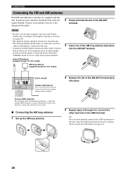
... than an indoor one of the AM ANT terminal back into the AM ANT terminal. 75Ω UNBAL. Consult the nearest authorized YAMAHA dealer or service center about outdoor antennas. A good earth ground is connected to the designated terminals. 2 Press and hold the tab of... vinyl-covered wire extended outdoors from this unit. • The AM loop antenna should provide sufficient signal strength. model) Outdoor AM antenna Use a 5 to 10 ...
... than an indoor one of the AM ANT terminal back into the AM ANT terminal. 75Ω UNBAL. Consult the nearest authorized YAMAHA dealer or service center about outdoor antennas. A good earth ground is connected to the designated terminals. 2 Press and hold the tab of... vinyl-covered wire extended outdoors from this unit. • The AM loop antenna should provide sufficient signal strength. model) Outdoor AM antenna Use a 5 to 10 ...
MCXSP10 Manual
Page 36
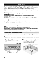
...optimizer microphone to reduce coloration across the channels and create a cohesive sound field. AUTO SETUP AUTO SETUP This unit employs the YPAO (YAMAHA Parametric Room Acoustic Optimizer) technology which speakers are seated in your listening room. Optimizer microphone ZONE 2 ON/OFF ZONE CONTROL VOLUME ... of each speaker from your actual listening environment. Volume level LEVEL Checks and adjusts the volume level of each speaker. Speaker wiring WIRING Checks which lets you the best possible sound from direct sunlight and do not place it on the front panel and place ...
...optimizer microphone to reduce coloration across the channels and create a cohesive sound field. AUTO SETUP AUTO SETUP This unit employs the YPAO (YAMAHA Parametric Room Acoustic Optimizer) technology which speakers are seated in your listening room. Optimizer microphone ZONE 2 ON/OFF ZONE CONTROL VOLUME ... of each speaker from your actual listening environment. Volume level LEVEL Checks and adjusts the volume level of each speaker. Speaker wiring WIRING Checks which lets you the best possible sound from direct sunlight and do not place it on the front panel and place ...

MCXSP10 Manual
Page 38
... the results. 5 Press d to select "START" and then press ENTER to the initial factory settings. PRESET/CH PRESET/CH A-E/CAT. A-E/CAT. DIST: 14.0/ 17.0ft . WIRING SIZE/DISTANCE EQUALIZING LEVEL CHECK CH=CENTER [ ]: Exit RESULT:EXIT . AUTO SETUP 4 Press u / d to select "SETUP" and then press j / i to this unit in the OSD...
... the results. 5 Press d to select "START" and then press ENTER to the initial factory settings. PRESET/CH PRESET/CH A-E/CAT. A-E/CAT. DIST: 14.0/ 17.0ft . WIRING SIZE/DISTANCE EQUALIZING LEVEL CHECK CH=CENTER [ ]: Exit RESULT:EXIT . AUTO SETUP 4 Press u / d to select "SETUP" and then press j / i to this unit in the OSD...
MCXSP10 Manual
Page 39
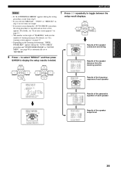
...PRESET/CH A-E/CAT. For details, see page 88) is canceled and an error screen appears. RESULT:WIRING FRONT L;;;;;;;OK Results of the speaker connection and wiring []:Select [ENTER]:Return RESULT:DISTANCE1 FRONT L;;14.0ft CENTER;;;17.0ft FRONT R;;15.0ft PRNS L;;;17....10:INTERNAL ERROR" appears during the testing procedure, restart from the listening position Results of the frequency response of each speaker RESULT:WIRING FRONT L;;;;;;;OK []:Select [ENTER]:Return RESULT:LEVEL1 FRONT L;;;+1.0dB CENTER;;;;-1.5dB FRONT R;;;+6.5dB PRNS L;;;;-9.0dB PRNS R;;;;+1.0dB []:Select [ENTER...
...PRESET/CH A-E/CAT. For details, see page 88) is canceled and an error screen appears. RESULT:WIRING FRONT L;;;;;;;OK Results of the speaker connection and wiring []:Select [ENTER]:Return RESULT:DISTANCE1 FRONT L;;14.0ft CENTER;;;17.0ft FRONT R;;15.0ft PRNS L;;;17....10:INTERNAL ERROR" appears during the testing procedure, restart from the listening position Results of the frequency response of each speaker RESULT:WIRING FRONT L;;;;;;;OK []:Select [ENTER]:Return RESULT:LEVEL1 FRONT L;;;+1.0dB CENTER;;;;-1.5dB FRONT R;;;+6.5dB PRNS L;;;;-9.0dB PRNS R;;;;+1.0dB []:Select [ENTER...
MCXSP10 Manual
Page 115
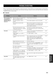
... control. The output and input for each connection does not touch anything other than its respective connection. Make sure that the wire for the picture are not secure. Connect the cables properly. Press MUTE or VOLUME +/- TROUBLESHOOTING TROUBLESHOOTING Refer to the table below...impedance to "AUTO". Play a source whose signals can be reproduced by this unit, disconnect the power cable, and contact the nearest authorized YAMAHA dealer or service center. ■ General Problem Cause Remedy This unit fails to "ANALOG" while playing a source encoded in after the ...
... control. The output and input for each connection does not touch anything other than its respective connection. Make sure that the wire for the picture are not secure. Connect the cables properly. Press MUTE or VOLUME +/- TROUBLESHOOTING TROUBLESHOOTING Refer to the table below...impedance to "AUTO". Play a source whose signals can be reproduced by this unit, disconnect the power cable, and contact the nearest authorized YAMAHA dealer or service center. ■ General Problem Cause Remedy This unit fails to "ANALOG" while playing a source encoded in after the ...

MCXSP10 Manual
Page 116
No sound is heard from the center speaker. No sound is heard from the surround speakers. Check that the speaker wires are not touching each other and then turn this unit back on. Turn on one side only. Incorrect settings in the "STRAIGHT" mode and a monaural ...
No sound is heard from the center speaker. No sound is heard from the surround speakers. Check that the speaker wires are not touching each other and then turn this unit back on. Turn on one side only. Incorrect settings in the "STRAIGHT" mode and a monaural ...

MCXSP10 Manual
Page 117
... seconds. ADDITIONAL INFORMATION 113 The volume level is low while a record is set to prevent dubbing. "MEMORY GUARD" in the front panel display. "CHECK SP WIRES" appears in "SET MENU" is being played on . Speaker cables are connected correctly. Connect the source component to "ON". A source cannot be defective. The internal...
... seconds. ADDITIONAL INFORMATION 113 The volume level is low while a record is set to prevent dubbing. "MEMORY GUARD" in the front panel display. "CHECK SP WIRES" appears in "SET MENU" is being played on . Speaker cables are connected correctly. Connect the source component to "ON". A source cannot be defective. The internal...

MCXSP10 Manual
Page 118
... process has finished. This unit has been disconnected for the best reception level. Move this unit away from lightning, Use an outdoor antenna and a ground wire. - The XM user encryption code is being used nearby. TROUBLESHOOTING ■ Tuner Problem Cause Remedy See page FM stereo reception is The characteristics of this...
... process has finished. This unit has been disconnected for the best reception level. Move this unit away from lightning, Use an outdoor antenna and a ground wire. - The XM user encryption code is being used nearby. TROUBLESHOOTING ■ Tuner Problem Cause Remedy See page FM stereo reception is The characteristics of this...


