
Owners Manual
Page 3
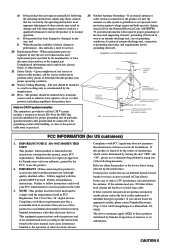
...FCC, to use the product. 2. The product should be the source of interference, which can not locate the appropriate retailer, please contact Yamaha Electronics Corp., U.S.A. 6660 Orangethorpe Ave, Buena Park, CA 90620. Article 810 of the National Electrical Code, ANSI/NFPA 70, provides ...information with the requirements listed in wire to a wall or ceiling only as recommended by the manufacturer or have the same characteristics as the original part. Modifications not expressly approved by Yamaha may cause interference harmful to the operation of antenna discharge...
...FCC, to use the product. 2. The product should be the source of interference, which can not locate the appropriate retailer, please contact Yamaha Electronics Corp., U.S.A. 6660 Orangethorpe Ave, Buena Park, CA 90620. Article 810 of the National Electrical Code, ANSI/NFPA 70, provides ...information with the requirements listed in wire to a wall or ceiling only as recommended by the manufacturer or have the same characteristics as the original part. Modifications not expressly approved by Yamaha may cause interference harmful to the operation of antenna discharge...
Owners Manual
Page 17
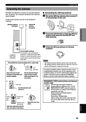
...(1/14) mm (inch) Open the cover of the 75-ohm coaxial cable and prepare it for the best reception. Insert the wire into moist earth. 75-ohm/300-ohm antenna adapter (U.K. PREPARATION Connecting the antennas Both AM and FM indoor antennas are included with ...this unit. 2 Press and hold the tab to insert the AM loop antenna lead wires into the AM ANT and GND terminals. Cut the external sleeve of the included 75-ohm/300-ohm ... the AM loop antenna, then connect it with pliers. Consult the nearest authorized YAMAHA dealer or service center about the outdoor antennas.
...(1/14) mm (inch) Open the cover of the 75-ohm coaxial cable and prepare it for the best reception. Insert the wire into moist earth. 75-ohm/300-ohm antenna adapter (U.K. PREPARATION Connecting the antennas Both AM and FM indoor antennas are included with ...this unit. 2 Press and hold the tab to insert the AM loop antenna lead wires into the AM ANT and GND terminals. Cut the external sleeve of the included 75-ohm/300-ohm ... the AM loop antenna, then connect it with pliers. Consult the nearest authorized YAMAHA dealer or service center about the outdoor antennas.
Owners Manual
Page 20
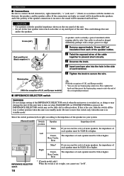
... y (With the exception of U.K. If this unit fails to turn on the rear panel of this unit. • Do not let the bare speaker wires touch each speaker must be 6 Ω or higher. Be sure to either position when this unit is in standby mode. CONNECTIONS I IMPEDANCE SELECTOR switch ... lack bass. This could damage this unit. One cable is incorrect, the sound will be heard from each of the speaker cables. 2 Twist the exposed wires of the cable together to prevent short circuits. 3 Unscrew the knob. 4 Insert one /two set (s) of main speakers, the impedance of each speaker ...
... y (With the exception of U.K. If this unit fails to turn on the rear panel of this unit. • Do not let the bare speaker wires touch each speaker must be 6 Ω or higher. Be sure to either position when this unit is in standby mode. CONNECTIONS I IMPEDANCE SELECTOR switch ... lack bass. This could damage this unit. One cable is incorrect, the sound will be heard from each of the speaker cables. 2 Twist the exposed wires of the cable together to prevent short circuits. 3 Unscrew the knob. 4 Insert one /two set (s) of main speakers, the impedance of each speaker ...
Owners Manual
Page 57
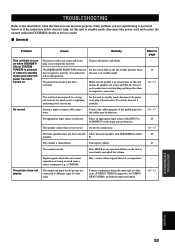
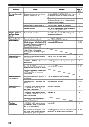
...signals which this unit cannot Play a source whose signals this unit to standby mode, disconnect the power cord, and contact the nearest authorized YAMAHA dealer or service center. The output and input for the picture are being received from a source component e.g; The power cord is not ...buttons on the unit to - external electric shock (such as lightning cord, plug it and strong static electricity). normally. Make sure all speaker wire connections on this unit and on all speakers are not secure. a CD-ROM. B. TROUBLESHOOTING Refer to the chart below does not help, ...
...signals which this unit cannot Play a source whose signals this unit to standby mode, disconnect the power cord, and contact the nearest authorized YAMAHA dealer or service center. The output and input for the picture are being received from a source component e.g; The power cord is not ...buttons on the unit to - external electric shock (such as lightning cord, plug it and strong static electricity). normally. Make sure all speaker wire connections on this unit and on all speakers are not secure. a CD-ROM. B. TROUBLESHOOTING Refer to the chart below does not help, ...
Owners Manual
Page 58
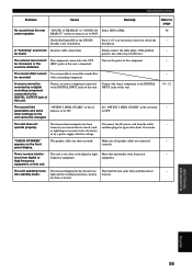
... decoding DSP program is Raise the level of the center speaker is being played with a Dolby Digital - One of a short circuit, etc. Check the speaker wires are not touching each speaker based on one side can be defective. Connect the cables properly. TROUBLESHOOTING Problem The sound suddenly goes off . No sound...
... decoding DSP program is Raise the level of the center speaker is being played with a Dolby Digital - One of a short circuit, etc. Check the speaker wires are not touching each speaker based on one side can be defective. Connect the cables properly. TROUBLESHOOTING Problem The sound suddenly goes off . No sound...
Owners Manual
Page 59
... "SOUND 1C REAR LR" or "SOUND 1D Select LRG or SML. 40 center speaker. There is too close to the digital or high- "CHECK SP WIRES" The speaker cables are connected - persists, the cables may be recorded. TROUBLESHOOTING Problem Cause Remedy Refer to page No sound from digital or frequency equipment...
... "SOUND 1C REAR LR" or "SOUND 1D Select LRG or SML. 40 center speaker. There is too close to the digital or high- "CHECK SP WIRES" The speaker cables are connected - persists, the cables may be recorded. TROUBLESHOOTING Problem Cause Remedy Refer to page No sound from digital or frequency equipment...
Owners Manual
Page 60
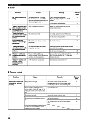
... that do not respond to noises. There are buzzing and A TV set , there are continuous Noises result from lightning, Use an outdoor antenna and a ground wire. 13 AM crackling and hissing fluorescent lamps, motors, thermostats This will function within a maximum range of FM stereo Check the antenna connections. 13 noisy. Try...
... that do not respond to noises. There are buzzing and A TV set , there are continuous Noises result from lightning, Use an outdoor antenna and a ground wire. 13 AM crackling and hissing fluorescent lamps, motors, thermostats This will function within a maximum range of FM stereo Check the antenna connections. 13 noisy. Try...

