
Owners Manual
Page 20
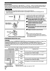
... shaped differently, perhaps with the markers on when STANDBY/ON (or SYSTEM POWER) is pressed, the IMPEDANCE SELECTOR switch may damage the unit. Center, The impedance of each speaker must be fully slid to turn on this unit is in the side of each speaker... positive (+) 3 Black: negative (-) 2 4 5 A speaker cord is actually a pair of insulated cables running side by side. CONNECTIONS I IMPEDANCE SELECTOR switch WARNING Do not change setting of the IMPEDANCE SELECTOR switch when the unit power is switched on the rear panel of this unit. • Do not let the bare speaker...
... shaped differently, perhaps with the markers on when STANDBY/ON (or SYSTEM POWER) is pressed, the IMPEDANCE SELECTOR switch may damage the unit. Center, The impedance of each speaker must be fully slid to turn on this unit is in the side of each speaker... positive (+) 3 Black: negative (-) 2 4 5 A speaker cord is actually a pair of insulated cables running side by side. CONNECTIONS I IMPEDANCE SELECTOR switch WARNING Do not change setting of the IMPEDANCE SELECTOR switch when the unit power is switched on the rear panel of this unit. • Do not let the bare speaker...
Owners Manual
Page 21
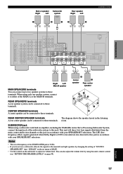
... SET selections. FM ANT S VIDEO OUTPUT L CENTER R MAIN REAR (SURROUND) REAR CENTER SUB WOOFER SPEAKERS A R REAR L (SURROUND) B R MAIN L CENTER REAR CENTER IMPEDANCE SELECTOR SET BEFORE POWER ON MAIN A OR B : 4ΩMIN. /SPEAKER MAIN A OR B : 8ΩMIN. /SPEAKER A+B : 8ΩMIN. /SPEAKER A+B : 16Ω..." on the subwoofer to these terminals. REAR CENTER SPEAKER terminals The diagram shows the speaker layout in amplifier, including the YAMAHA Active Servo Processing Subwoofer System, connect the input jack of "SOUND 1 SPEAKER SET" item "1E BASS" on the set...
... SET selections. FM ANT S VIDEO OUTPUT L CENTER R MAIN REAR (SURROUND) REAR CENTER SUB WOOFER SPEAKERS A R REAR L (SURROUND) B R MAIN L CENTER REAR CENTER IMPEDANCE SELECTOR SET BEFORE POWER ON MAIN A OR B : 4ΩMIN. /SPEAKER MAIN A OR B : 8ΩMIN. /SPEAKER A+B : 8ΩMIN. /SPEAKER A+B : 16Ω..." on the subwoofer to these terminals. REAR CENTER SPEAKER terminals The diagram shows the speaker layout in amplifier, including the YAMAHA Active Servo Processing Subwoofer System, connect the input jack of "SOUND 1 SPEAKER SET" item "1E BASS" on the set...
Owners Manual
Page 22
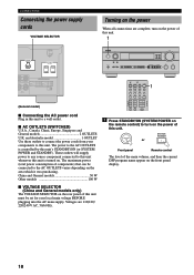
... PRESET/TUNING FM/AM EDIT TUNING MODE MEMORY AUTO/MANUAL MONO MAN`L/AUTO FM VOLUME VIDEO AUX S VIDEO VIDEO L AUDIO R OPTICAL BASS TREBLE L REAR CENTER IMPEDANCE SELECTOR SET BEFORE POWER ON MAIN A OR B : 4ΩMIN. /SPEAKER A+B : 8ΩMIN. /SPEAKER CENTER : 6ΩMIN. /SPEAKER REAR CENTER: 6ΩMIN. /... volume, and then the current DSP program name appear on the area which it was purchasing. CONNECTIONS Connecting the power supply cords VOLTAGE SELECTOR Turning on the power When all connections are 110/120/ 220/240 V AC, 50/60 Hz. and Australia model 1 OUTLET Use...
... PRESET/TUNING FM/AM EDIT TUNING MODE MEMORY AUTO/MANUAL MONO MAN`L/AUTO FM VOLUME VIDEO AUX S VIDEO VIDEO L AUDIO R OPTICAL BASS TREBLE L REAR CENTER IMPEDANCE SELECTOR SET BEFORE POWER ON MAIN A OR B : 4ΩMIN. /SPEAKER A+B : 8ΩMIN. /SPEAKER CENTER : 6ΩMIN. /SPEAKER REAR CENTER: 6ΩMIN. /... volume, and then the current DSP program name appear on the area which it was purchasing. CONNECTIONS Connecting the power supply cords VOLTAGE SELECTOR Turning on the power When all connections are 110/120/ 220/240 V AC, 50/60 Hz. and Australia model 1 OUTLET Use...
Owners Manual
Page 57
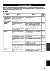
...or right position when the rear panel is not fully set this unit to standby mode, disconnect the power cord, and contact the nearest authorized YAMAHA dealer or service center. The speaker connections are secure and that the wire for the picture are being received from a source component e.g; Press ... . I General Problem Cause Remedy Refer to page This unit fails to turn on Set the switch fully to the left or right position. The IMPEDANCE SELECTOR switch on when STANDBY/ ON (or SYSTEM POWER) is pressed, or enters in standby mode soon after 30 seconds, then use it and strong ...
...or right position when the rear panel is not fully set this unit to standby mode, disconnect the power cord, and contact the nearest authorized YAMAHA dealer or service center. The speaker connections are secure and that the wire for the picture are being received from a source component e.g; Press ... . I General Problem Cause Remedy Refer to page This unit fails to turn on Set the switch fully to the left or right position. The IMPEDANCE SELECTOR switch on when STANDBY/ ON (or SYSTEM POWER) is pressed, or enters in standby mode soon after 30 seconds, then use it and strong ...
Owners Manual
Page 58
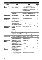
... turn the unit back on the set menu Select the appropriate mode for your system does not include a subwoofer. Remedy Refer to page Check the IMPEDANCE SELECTOR switch is set to 4) Select another DSP program. 25 - 30 A digital signal with Dolby Surround, Dolby Digital or DTS. Check the speaker wires are not...
... turn the unit back on the set menu Select the appropriate mode for your system does not include a subwoofer. Remedy Refer to page Check the IMPEDANCE SELECTOR switch is set to 4) Select another DSP program. 25 - 30 A digital signal with Dolby Surround, Dolby Digital or DTS. Check the speaker wires are not...


