Owner's Manual
Page 2
...- All operating and other appliances that may impede the flow of the unit. 15 Damage Requiring Service - The unit should be unplugged from power lines. 18 Grounding or Polarization - The unit does not appear to overturn. 7 Wall or Ceiling Mounting - The exclamation point within the... product's enclosure that produce heat. 10 Power Sources - or placed in a built-in performance; The safety and operating instructions should be read before the unit is not defeated. SAFETY ...
...- All operating and other appliances that may impede the flow of the unit. 15 Damage Requiring Service - The unit should be unplugged from power lines. 18 Grounding or Polarization - The unit does not appear to overturn. 7 Wall or Ceiling Mounting - The exclamation point within the... product's enclosure that produce heat. 10 Power Sources - or placed in a built-in performance; The safety and operating instructions should be read before the unit is not defeated. SAFETY ...
Owner's Manual
Page 3
... (NEC SECTION 810-20) GROUNDING CONDUCTORS (NEC SECTION 810-21) GROUND CLAMPS POWER SERVICE GROUNDING ELECTRODE SYSTEM (NEC ART 250. Compliance with this product MUST be determined by Yamaha Corporation of antenna discharge unit, connection to avoid prolonged exposure from loud sounds is...the antenna. This equipment generates/uses radio frequencies and, if not installed and used . We Want You Listening For A Lifetime YAMAHA and the Electronic Industries Association's Consumer Electronics Group want you can be used according to the instructions found to accessories and/or...
... (NEC SECTION 810-20) GROUNDING CONDUCTORS (NEC SECTION 810-21) GROUND CLAMPS POWER SERVICE GROUNDING ELECTRODE SYSTEM (NEC ART 250. Compliance with this product MUST be determined by Yamaha Corporation of antenna discharge unit, connection to avoid prolonged exposure from loud sounds is...the antenna. This equipment generates/uses radio frequencies and, if not installed and used . We Want You Listening For A Lifetime YAMAHA and the Electronic Industries Association's Consumer Electronics Group want you can be used according to the instructions found to accessories and/or...

Owner's Manual
Page 4
...wall outlet until all connections are 110/120/220/240 V AC, 50/60 Hz. Contact qualified YAMAHA service personnel when any reasons. 16 When not planning to use of time (i.e. vacation), disconnect the AC power plug from the wall outlet. 19 VOLTAGE SELECTOR (China and General models only) The VOLTAGE SELECTOR... - IMPORTANT Please record the serial number of this unit. - do not pull the cord. 11 Do not clean this unit with Canadian ICES-003. YAMAHA will not be used. MODEL: Serial No.: The serial number is dangerous and may cause fire, damage to this unit, and/or personal injury. ...
...wall outlet until all connections are 110/120/220/240 V AC, 50/60 Hz. Contact qualified YAMAHA service personnel when any reasons. 16 When not planning to use of time (i.e. vacation), disconnect the AC power plug from the wall outlet. 19 VOLTAGE SELECTOR (China and General models only) The VOLTAGE SELECTOR... - IMPORTANT Please record the serial number of this unit. - do not pull the cord. 11 Do not clean this unit with Canadian ICES-003. YAMAHA will not be used. MODEL: Serial No.: The serial number is dangerous and may cause fire, damage to this unit, and/or personal injury. ...
Owner's Manual
Page 5
... Audio Components 12 Connecting an External Decoder 12 Connecting Video Components 14 Connecting Speakers 16 IMPEDANCE SELECTOR Switch 18 Connecting the Power Supply Cords 18 ADJUSTING THE SPEAKER BALANCE .... 19 Before You Start Adjusting 19 Using the Test Tone 19 BASIC OPERATION ... the Factory Setting 46 SOUND FIELD PROGRAM 47 Hi-Fi DSP Programs 47 CINEMA DSP Programs 47 APPENDIX TROUBLESHOOTING 50 SPECIFICATIONS (HTR-5450 54 SPECIFICATIONS (HTR-5440 55 GLOSSARY 56 INDEX 58 BASIC OPERATION ADVANCED OPERATION APPENDIX English 1 SET (Dolby Digital set 35 6 DTS SET ...
... Audio Components 12 Connecting an External Decoder 12 Connecting Video Components 14 Connecting Speakers 16 IMPEDANCE SELECTOR Switch 18 Connecting the Power Supply Cords 18 ADJUSTING THE SPEAKER BALANCE .... 19 Before You Start Adjusting 19 Using the Test Tone 19 BASIC OPERATION ... the Factory Setting 46 SOUND FIELD PROGRAM 47 Hi-Fi DSP Programs 47 CINEMA DSP Programs 47 APPENDIX TROUBLESHOOTING 50 SPECIFICATIONS (HTR-5450 54 SPECIFICATIONS (HTR-5440 55 GLOSSARY 56 INDEX 58 BASIC OPERATION ADVANCED OPERATION APPENDIX English 1 SET (Dolby Digital set 35 6 DTS SET ...
Owner's Manual
Page 6
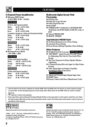
... YAMAHA DSP Technology and Dolby Digital, Dolby Pro Logic or DTS N Virtual CINEMA DSP N SILENT CINEMA Sophisticated FM/AM Tuner N 40-Station Random Access Preset Tuning N Automatic Preset Tuning N Preset Station Shifting Capability (Preset Editing) Other Features N 96-kHz/24-bit D/A Converter HTR-5450 ...name. Manufactured under license from Digital Theater Systems, Inc. All Rights Reserved. 2 FEATURES 5-Channel Power Amplification N Minimum RMS Output (0.06% THD, 20 Hz - 20 kHz) HTR-5450 [U.S.A. In cases when the button names differ between the main unit and the remote control, ...
... YAMAHA DSP Technology and Dolby Digital, Dolby Pro Logic or DTS N Virtual CINEMA DSP N SILENT CINEMA Sophisticated FM/AM Tuner N 40-Station Random Access Preset Tuning N Automatic Preset Tuning N Preset Station Shifting Capability (Preset Editing) Other Features N 96-kHz/24-bit D/A Converter HTR-5450 ...name. Manufactured under license from Digital Theater Systems, Inc. All Rights Reserved. 2 FEATURES 5-Channel Power Amplification N Minimum RMS Output (0.06% THD, 20 Hz - 20 kHz) HTR-5450 [U.S.A. In cases when the button names differ between the main unit and the remote control, ...
Owner's Manual
Page 8
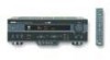
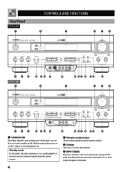
Standby mode In this mode, this unit consumes a very small quantity of power to receive infrared-signals from the remote control. 2 Remote control sensor This receives signals from the remote control. 3 Display This shows various information. 4... and ANALOG for the sources that send two or more types of this unit or to set the volume at the minimum level. Front Panel HTR-5450 1 CONTROLS AND FUNCTIONS 2 3 456 STANDBY /ON D I G I TA L SURROUND BASS TREBLE BALANCE -+ -+ L R SPEAKERS A B ON OFF D I G I TA L VOLUME PROGRAM EFFECT PRESET/TUNING PHONES S VIDEO VIDEO L ...
Standby mode In this mode, this unit consumes a very small quantity of power to receive infrared-signals from the remote control. 2 Remote control sensor This receives signals from the remote control. 3 Display This shows various information. 4... and ANALOG for the sources that send two or more types of this unit or to set the volume at the minimum level. Front Panel HTR-5450 1 CONTROLS AND FUNCTIONS 2 3 456 STANDBY /ON D I G I TA L SURROUND BASS TREBLE BALANCE -+ -+ L R SPEAKERS A B ON OFF D I G I TA L VOLUME PROGRAM EFFECT PRESET/TUNING PHONES S VIDEO VIDEO L ...
Owner's Manual
Page 10
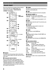
..."Setting the Manufacturer Code".) When the component selector button has been pressed, the remote control is set to that component operation mode. 3 POWER Each time you want to control with the remote control. A/B/C/D/E: To select one of these buttons which corresponds to the component you press ...this button, the unit switches between the power on and standby mode. 4 TEST Press this button to select the items in red when pressing a button on the component selector. ...
..."Setting the Manufacturer Code".) When the component selector button has been pressed, the remote control is set to that component operation mode. 3 POWER Each time you want to control with the remote control. A/B/C/D/E: To select one of these buttons which corresponds to the component you press ...this button, the unit switches between the power on and standby mode. 4 TEST Press this button to select the items in red when pressing a button on the component selector. ...
Owner's Manual
Page 13
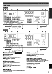
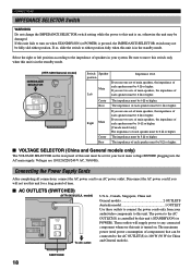
.... 8 AC OUTLET(S) Use these outlets to supply power to your other audio/video components (see page 18). Set this unit in the standby mode before you change the setting of this switch to match the amplifier output to your speaker impedance. Rear Panel HTR-5450 12 3 4 5 CONTROLS AND FUNCTIONS 6 78 INTRODUCTION PREPARATION DIGITAL...
.... 8 AC OUTLET(S) Use these outlets to supply power to your other audio/video components (see page 18). Set this unit in the standby mode before you change the setting of this switch to match the amplifier output to your speaker impedance. Rear Panel HTR-5450 12 3 4 5 CONTROLS AND FUNCTIONS 6 78 INTRODUCTION PREPARATION DIGITAL...

Owner's Manual
Page 14
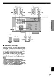
..., the sound will probably be the same. Best results, however, are used for the main source sound plus the effect sounds. The YAMAHA Active Servo Processing Subwoofer System is designed to provide the best sound-field quality with the addition of the TV monitor should be high-performance...highperformance models that case, "CENTER SP" in your system, the tone of a moving human voice and other speakers do not have enough power-handling capacity to place the subwoofer near the main speakers. We recommend that you can reproduce sounds over or under the monitor and centrally between...
..., the sound will probably be the same. Best results, however, are used for the main source sound plus the effect sounds. The YAMAHA Active Servo Processing Subwoofer System is designed to provide the best sound-field quality with the addition of the TV monitor should be high-performance...highperformance models that case, "CENTER SP" in your system, the tone of a moving human voice and other speakers do not have enough power-handling capacity to place the subwoofer near the main speakers. We recommend that you can reproduce sounds over or under the monitor and centrally between...
Owner's Manual
Page 15
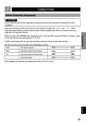
...!, #, $ etc. INTRODUCTION CONNECTIONS Before Connecting Components CAUTION Never connect this unit. Refer to the instructions for each component to mains power until all connections between components have different terminal names. Use RCA-type pin plug cables for connecting audio/video components with the same ...V White analog audio signals for the left channel L L Red analog audio signals for pin plugs can be connected to this unit and other YAMAHA audio components (such as a tape deck, MD recorder and CD player or changer), connect it to "-". The input and output jacks for ...
...!, #, $ etc. INTRODUCTION CONNECTIONS Before Connecting Components CAUTION Never connect this unit. Refer to the instructions for each component to mains power until all connections between components have different terminal names. Use RCA-type pin plug cables for connecting audio/video components with the same ...V White analog audio signals for the left channel L L Red analog audio signals for pin plugs can be connected to this unit and other YAMAHA audio components (such as a tape deck, MD recorder and CD player or changer), connect it to "-". The input and output jacks for ...
Owner's Manual
Page 16
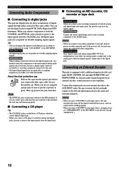
...the cap. Note • The OPTICAL jacks on this unit. Notes • When you connect a recording component to this unit, keep its power on your recording component to the AUDIO jacks. This cap protects the jack from an external decoder, sound processor or pre-amplifier. When you are... When you connect a CD player to both the analog and digital jacks, priority is given to the input signals from other components. • HTR-5450 only Since digital output and analog output (REC OUT) are independent of each digital jack according to your component by a recording component connected to ...
...the cap. Note • The OPTICAL jacks on this unit. Notes • When you connect a recording component to this unit, keep its power on your recording component to the AUDIO jacks. This cap protects the jack from an external decoder, sound processor or pre-amplifier. When you are... When you connect a CD player to both the analog and digital jacks, priority is given to the input signals from other components. • HTR-5450 only Since digital output and analog output (REC OUT) are independent of each digital jack according to your component by a recording component connected to ...
Owner's Manual
Page 21
... BASIC OPERATION ADVANCED OPERATION Main speakers A Main speakers B CONNECTIONS Right Left Right R+ A SPEAKERS - - +L MAIN B CENTER REAR R (SURROUND) L + - IMPEDANCE SELECTOR SET BEFORE POWER ON MAIN A OR B: 8 MIN. /SPEAKER A + B:16 MIN. /SPEAKER CENTER : 8 MIN. /SPEAKER REAR : 8 MIN. /SPEAKER MAIN A OR B: 4 MIN. ... "1 SPEAKER SET", "LFE LEVEL (5 DOLBY D. SET)" and "6 DTS SET" in amplifier, including the YAMAHA Active Servo Processing Subwoofer System, connect the input jack of this jack is 90 Hz.) The LFE (low-...assigned to this jack. TOTAL Left (HTR-5450/U.S.A.
... BASIC OPERATION ADVANCED OPERATION Main speakers A Main speakers B CONNECTIONS Right Left Right R+ A SPEAKERS - - +L MAIN B CENTER REAR R (SURROUND) L + - IMPEDANCE SELECTOR SET BEFORE POWER ON MAIN A OR B: 8 MIN. /SPEAKER A + B:16 MIN. /SPEAKER CENTER : 8 MIN. /SPEAKER REAR : 8 MIN. /SPEAKER MAIN A OR B: 4 MIN. ... "1 SPEAKER SET", "LFE LEVEL (5 DOLBY D. SET)" and "6 DTS SET" in amplifier, including the YAMAHA Active Servo Processing Subwoofer System, connect the input jack of this jack is 90 Hz.) The LFE (low-...assigned to this jack. TOTAL Left (HTR-5450/U.S.A.
Owner's Manual
Page 22
...) The VOLTAGE SELECTOR on the rear panel of each speaker must be 8 Ω or higher. I AC OUTLETS (SWITCHED) (HTR-5450/U.S.A. The power to the AC OUTLET(S) is in the standby mode. If so, slide the switch to either position. If you use two sets... higher. Right Main Center Rear If you use one set of main speakers, the impedance of speakers in the standby mode. (HTR-5450/General model) IMPEDANCE SELECTOR IMPEDANCE SELECTOR SET BEFORE POWER ON MAIN A OR B: 8 MIN. /SPEAKER A + B:16 MIN. /SPEAKER CENTER : 8 MIN. /SPEAKER REAR : 8 MIN. /SPEAKER MAIN A OR B: 4 MIN....
...) The VOLTAGE SELECTOR on the rear panel of each speaker must be 8 Ω or higher. I AC OUTLETS (SWITCHED) (HTR-5450/U.S.A. The power to the AC OUTLET(S) is in the standby mode. If so, slide the switch to either position. If you use two sets... higher. Right Main Center Rear If you use one set of main speakers, the impedance of speakers in the standby mode. (HTR-5450/General model) IMPEDANCE SELECTOR IMPEDANCE SELECTOR SET BEFORE POWER ON MAIN A OR B: 8 MIN. /SPEAKER A + B:16 MIN. /SPEAKER CENTER : 8 MIN. /SPEAKER REAR : 8 MIN. /SPEAKER MAIN A OR B: 4 MIN....
Owner's Manual
Page 23
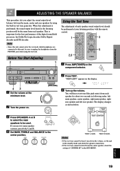
... TEST L SUR. "TEST LEFT" appears on the component selector. 2 Press TEST. This is performed, the sound output level heard at the minimum level. (HTR-5450) VOLUME 2 Turn the power on. You will be used. Note • Since this unit cannot enter the test mode while headphones are connected to this adjustment is important...
... TEST L SUR. "TEST LEFT" appears on the component selector. 2 Press TEST. This is performed, the sound output level heard at the minimum level. (HTR-5450) VOLUME 2 Turn the power on. You will be used. Note • Since this unit cannot enter the test mode while headphones are connected to this adjustment is important...
Owner's Manual
Page 25
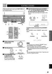
...6CH INPUT" appears on the display. 6CH INPUT or Front panel Remote control 1 Set the volume at the VOLUME minimum level. 2 Turn the power on the video monitor for details. y • The current input mode is also shown. Refer to turn off "6CH INPUT". • ... VIDEO L AUDIO R OPTICAL A/B/C/D/E PRESET /TUNING FM/AM EDIT MEMORY TUNING MODE MAN'L/AUTO FM AUTO/MAN'L MONO INPUT MODE INPUT 6CH INPUT SILENT VIDEO AUX 7 (HTR-5450) 4 6 2 4 7 4 Select the desired input source with INPUT l / h (or the input selector buttons). (Turn on . INPUT or Front panel Remote control...
...6CH INPUT" appears on the display. 6CH INPUT or Front panel Remote control 1 Set the volume at the VOLUME minimum level. 2 Turn the power on the video monitor for details. y • The current input mode is also shown. Refer to turn off "6CH INPUT". • ... VIDEO L AUDIO R OPTICAL A/B/C/D/E PRESET /TUNING FM/AM EDIT MEMORY TUNING MODE MAN'L/AUTO FM AUTO/MAN'L MONO INPUT MODE INPUT 6CH INPUT SILENT VIDEO AUX 7 (HTR-5450) 4 6 2 4 7 4 Select the desired input source with INPUT l / h (or the input selector buttons). (Turn on . INPUT or Front panel Remote control...
Owner's Manual
Page 26
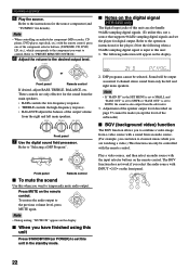
... REMOTE CONTROL". 6 Adjust the volume to the previous volume level, press MUTE again. PROGRAM or Front panel Remote control I Notes on the digital signal HTR-5450 only The digital input jacks of this unit can only be controlled with the remote control, press one of the component selector buttons, (TAPE/MD...and "BASS OUT" is set to SWFR or "BASS OUT" is set to BOTH, the sound is input to this unit Press STANDBY/ON (or POWER) to "Selecting a DSP Program". DSP programs cannot be output as normal 2-channel stereo sound from the subwoofer. 3. VOLUME or Front panel Remote control If...
... REMOTE CONTROL". 6 Adjust the volume to the previous volume level, press MUTE again. PROGRAM or Front panel Remote control I Notes on the digital signal HTR-5450 only The digital input jacks of this unit can only be controlled with the remote control, press one of the component selector buttons, (TAPE/MD...and "BASS OUT" is set to SWFR or "BASS OUT" is set to BOTH, the sound is input to this unit Press STANDBY/ON (or POWER) to "Selecting a DSP Program". DSP programs cannot be output as normal 2-channel stereo sound from the subwoofer. 3. VOLUME or Front panel Remote control If...
Owner's Manual
Page 28
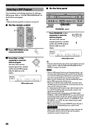
.... • When you select an input source, this unit automatically selects the last DSP program used . • HTR-5450 only When 96-kHz sampling digital signals are automatically selected when you turn on the power again. • If a Dolby Digital or DTS signal is input when the input mode is set to NON.../TUNING PHONES S VIDEO VIDEO L AUDIO R OPTICAL A/B/C/D/E PRESET /TUNING FM/AM EDIT MEMORY TUNING MODE MAN'L/AUTO FM AUTO/MAN'L MONO INPUT MODE INPUT 6CH INPUT (HTR-5450) SILENT VIDEO AUX PROGRAM / Press PROGRAM l or h repeatedly to select the desired program.
.... • When you select an input source, this unit automatically selects the last DSP program used . • HTR-5450 only When 96-kHz sampling digital signals are automatically selected when you turn on the power again. • If a Dolby Digital or DTS signal is input when the input mode is set to NON.../TUNING PHONES S VIDEO VIDEO L AUDIO R OPTICAL A/B/C/D/E PRESET /TUNING FM/AM EDIT MEMORY TUNING MODE MAN'L/AUTO FM AUTO/MAN'L MONO INPUT MODE INPUT 6CH INPUT (HTR-5450) SILENT VIDEO AUX PROGRAM / Press PROGRAM l or h repeatedly to select the desired program.
Owner's Manual
Page 29
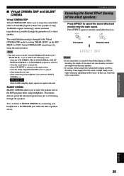
... mode even if "REAR LR SP" is performed by using the main speakers. or - This feature delivers powerful surround reproduction just as the input source; - EFFECT or Front panel Remote control Notes • If the... Digital or DTS is decoding, it may happen that case, turn the sound effect back on. Using YAMAHA original technology, natural surround reproduction is output faintly or not output normally, depending on the sound effect. ... input to NON. The sound field processing is selected; - HTR-5450 only when 96-kHz sampling digital signals are on the SET MENU to this unit.
... mode even if "REAR LR SP" is performed by using the main speakers. or - This feature delivers powerful surround reproduction just as the input source; - EFFECT or Front panel Remote control Notes • If the... Digital or DTS is decoding, it may happen that case, turn the sound effect back on. Using YAMAHA original technology, natural surround reproduction is output faintly or not output normally, depending on the sound effect. ... input to NON. The sound field processing is selected; - HTR-5450 only when 96-kHz sampling digital signals are on the SET MENU to this unit.

Owner's Manual
Page 30
...outdoor AM antenna is connected to this unit. • The AM loop antenna should always be removed from the AC outlet. Consult the nearest authorized YAMAHA dealer or service center about the outdoor antennas. 26 A good earth ground is obtained. Note • Do not connect an outdoor FM antenna and...in your area. North, Central and South America: 100 kHz/ 10 kHz Other area: 50 kHz/9 kHz Before setting this switch, disconnect the AC power plug of this unit. I Connecting the indoor FM antenna Connect the included indoor FM antenna to the FM ANT 75Ω UNBAL. FREQUENCY STEP ...
...outdoor AM antenna is connected to this unit. • The AM loop antenna should always be removed from the AC outlet. Consult the nearest authorized YAMAHA dealer or service center about the outdoor antennas. 26 A good earth ground is obtained. Note • Do not connect an outdoor FM antenna and...in your area. North, Central and South America: 100 kHz/ 10 kHz Other area: 50 kHz/9 kHz Before setting this switch, disconnect the AC power plug of this unit. I Connecting the indoor FM antenna Connect the included indoor FM antenna to the FM ANT 75Ω UNBAL. FREQUENCY STEP ...
Owner's Manual
Page 32
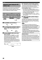
...or begin tuning toward the higher frequencies. STANDBY /ON D I G I TA L SURROUND BASS TREBLE BALANCE -+ -+ L R SPEAKERS A B ON OFF (HTR-5450) D I G I When automatic preset tuning is completed The display shows the frequency of received stations is stored along with the station frequency. • You ...can select the preset number from the AC power outlet or the power is set in monaural mode and store it manually in the standby mode. I TA L VOLUME PROGRAM EFFECT PRESET/TUNING...
...or begin tuning toward the higher frequencies. STANDBY /ON D I G I TA L SURROUND BASS TREBLE BALANCE -+ -+ L R SPEAKERS A B ON OFF (HTR-5450) D I G I When automatic preset tuning is completed The display shows the frequency of received stations is stored along with the station frequency. • You ...can select the preset number from the AC power outlet or the power is set in monaural mode and store it manually in the standby mode. I TA L VOLUME PROGRAM EFFECT PRESET/TUNING...


