Owner's Manual
Page 3
... quality shielded cables. One that are on different branch (circuit breaker or fuse) circuits or install AC line filter/s. SAFETY INSTRUCTIONS EXAMPLE OF ANTENNA GROUNDING MAST GROUND CLAMP ELECTRIC SERVICE EQUIPMENT NEC - This equipment generates/uses radio frequencies and, if not installed and used . Note to provide some protection against voltage surges and built-up static charges. NATIONAL ELECTRICAL CODE ANTENNA LEAD IN WIRE ANTENNA DISCHARGE...
... quality shielded cables. One that are on different branch (circuit breaker or fuse) circuits or install AC line filter/s. SAFETY INSTRUCTIONS EXAMPLE OF ANTENNA GROUNDING MAST GROUND CLAMP ELECTRIC SERVICE EQUIPMENT NEC - This equipment generates/uses radio frequencies and, if not installed and used . Note to provide some protection against voltage surges and built-up static charges. NATIONAL ELECTRICAL CODE ANTENNA LEAD IN WIRE ANTENNA DISCHARGE...
Owner's Manual
Page 5
... (Dolby Digital set 35 6 DTS SET (DTS LFE level 36 7 SP DLY TIME (center delay 36 8 DISPLAY SET 36 9 MEM. INTRODUCTION PREPARATION INTRODUCTION CONTENTS INTRODUCTION FEATURES 2 GETTING STARTED 3 Checking the Package Contents 3 Battery Installation in the Remote Control 3 Battery Replacement 3 CONTROLS AND FUNCTIONS 4 Front Panel 4 Remote Control 6 Using the Remote Control 7 Display 8 Rear Panel 9 PREPARATION SPEAKER SETUP 10 Speakers to the Factory Setting 46 SOUND FIELD PROGRAM 47 Hi-Fi DSP Programs 47 CINEMA DSP Programs 47 APPENDIX TROUBLESHOOTING 50 SPECIFICATIONS...
... (Dolby Digital set 35 6 DTS SET (DTS LFE level 36 7 SP DLY TIME (center delay 36 8 DISPLAY SET 36 9 MEM. INTRODUCTION PREPARATION INTRODUCTION CONTENTS INTRODUCTION FEATURES 2 GETTING STARTED 3 Checking the Package Contents 3 Battery Installation in the Remote Control 3 Battery Replacement 3 CONTROLS AND FUNCTIONS 4 Front Panel 4 Remote Control 6 Using the Remote Control 7 Display 8 Rear Panel 9 PREPARATION SPEAKER SETUP 10 Speakers to the Factory Setting 46 SOUND FIELD PROGRAM 47 Hi-Fi DSP Programs 47 CINEMA DSP Programs 47 APPENDIX TROUBLESHOOTING 50 SPECIFICATIONS...
Owner's Manual
Page 6
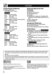
... buttons on the main unit or on various functions unique to each model, see the descriptions given for Other Future Formats N Video Signal Input and Output Capability (Including S Video Connections HTR-5450 only ) N Optical and Coaxial Digital Signal Input Jacks N SLEEP Timer N Remote Control with Preset Manufacturer Codes • This document is given in parentheses in this manual. "DTS" and "DTS Digital Surround" are trademarks of YAMAHA DSP Technology and Dolby Digital, Dolby Pro Logic or DTS N Virtual CINEMA DSP N SILENT CINEMA Sophisticated FM/AM Tuner N 40-Station...
... buttons on the main unit or on various functions unique to each model, see the descriptions given for Other Future Formats N Video Signal Input and Output Capability (Including S Video Connections HTR-5450 only ) N Optical and Coaxial Digital Signal Input Jacks N SLEEP Timer N Remote Control with Preset Manufacturer Codes • This document is given in parentheses in this manual. "DTS" and "DTS Digital Surround" are trademarks of YAMAHA DSP Technology and Dolby Digital, Dolby Pro Logic or DTS N Virtual CINEMA DSP N SILENT CINEMA Sophisticated FM/AM Tuner N 40-Station...
Owner's Manual
Page 8
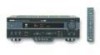
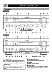
... from the remote control. 3 Display This shows various information. 4 INPUT MODE Press this button to select the input mode among AUTO, DTS and ANALOG for the sources that send two or more types of this unit or to this unit in the standby mode. Before turning the power on the power of signals to set the volume at the minimum level. Front Panel HTR-5450 1 CONTROLS AND FUNCTIONS 2 3 456 STANDBY /ON D I G I TA L SURROUND BASS TREBLE BALANCE -+ -+ L R SPEAKERS A B ON OFF D I G I TA L VOLUME PROGRAM EFFECT PRESET/TUNING PHONES S VIDEO VIDEO L AUDIO R OPTICAL...
... from the remote control. 3 Display This shows various information. 4 INPUT MODE Press this button to select the input mode among AUTO, DTS and ANALOG for the sources that send two or more types of this unit or to this unit in the standby mode. Before turning the power on the power of signals to set the volume at the minimum level. Front Panel HTR-5450 1 CONTROLS AND FUNCTIONS 2 3 456 STANDBY /ON D I G I TA L SURROUND BASS TREBLE BALANCE -+ -+ L R SPEAKERS A B ON OFF D I G I TA L VOLUME PROGRAM EFFECT PRESET/TUNING PHONES S VIDEO VIDEO L AUDIO R OPTICAL...
Owner's Manual
Page 9
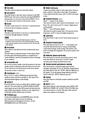
... the PHONES jack so that this unit outputs audio signals for the main speaker system (connected to this unit) that of the selected input source appears on the display. i MEMORY (MAN'L/AUTO FM) Press this button to switch the tuning mode between automatic and manual. o TUNING MODE (AUTO/MAN'L MONO) Press this button to store the broadcasting stations. APPENDIX English 5 Turn the control to adjust the balance of 5 preset station groups (A to E). In that the "AUTO" indicator lights up...
... the PHONES jack so that this unit outputs audio signals for the main speaker system (connected to this unit) that of the selected input source appears on the display. i MEMORY (MAN'L/AUTO FM) Press this button to switch the tuning mode between automatic and manual. o TUNING MODE (AUTO/MAN'L MONO) Press this button to store the broadcasting stations. APPENDIX English 5 Turn the control to adjust the balance of 5 preset station groups (A to E). In that the "AUTO" indicator lights up...
Owner's Manual
Page 10
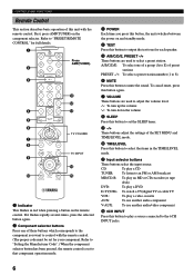
... flashes rapidly several times, press the selected button again. 2 Component selector buttons Press one of a group (A to E) of preset stations PRESET -/+: To select a preset station number (1 to 8) 6 MUTE Press this button to output the test tone for each speaker. 5 A/B/C/D/E, PRESET -/+ These buttons are used to "PRESET REMOTE CONTROL" for your component. A/B/C/D/E: To select one of these buttons which corresponds to the component you press this button, the unit switches between the power on and standby mode. 4 TEST Press this button to mute the sound. CD: To play...
... flashes rapidly several times, press the selected button again. 2 Component selector buttons Press one of a group (A to E) of preset stations PRESET -/+: To select a preset station number (1 to 8) 6 MUTE Press this button to output the test tone for each speaker. 5 A/B/C/D/E, PRESET -/+ These buttons are used to "PRESET REMOTE CONTROL" for your component. A/B/C/D/E: To select one of these buttons which corresponds to the component you press this button, the unit switches between the power on and standby mode. 4 TEST Press this button to mute the sound. CD: To play...
Owner's Manual
Page 13
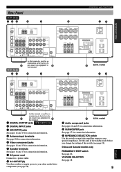
... the standby mode before you change the setting of this switch to match the amplifier output to your speaker impedance. model) 78 BASIC OPERATION ADVANCED OPERATION DIGITAL INPUT CD AM ANT GND TUNER FM ANT COAXIAL OPTICAL D-TV/CBL DVD 6CH INPUT MAIN SURROUND CENTER L L 75 UNBAL. q (U.S.A. model) 9 Audio component jacks See pages 12 and 13 for connection information. 0 SUBWOOFER jack See page 17 for connection information. 7 AC power cord Connect to a power outlet. 8 AC OUTLET(S) Use these outlets to supply power to your other audio/video components...
... the standby mode before you change the setting of this switch to match the amplifier output to your speaker impedance. model) 78 BASIC OPERATION ADVANCED OPERATION DIGITAL INPUT CD AM ANT GND TUNER FM ANT COAXIAL OPTICAL D-TV/CBL DVD 6CH INPUT MAIN SURROUND CENTER L L 75 UNBAL. q (U.S.A. model) 9 Audio component jacks See pages 12 and 13 for connection information. 0 SUBWOOFER jack See page 17 for connection information. 7 AC power cord Connect to a power outlet. 8 AC OUTLET(S) Use these outlets to supply power to your other audio/video components...
Owner's Manual
Page 21
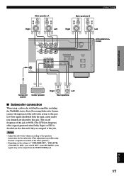
... Dolby Digital or DTS is possible using a subwoofer with built-in the SET MENU, some signals may not be output from the main, center and/or rear channels are assigned to the operation instructions for the subwoofer. (Fine adjustment is decoded are also directed if they are directed to this jack. (The cut-off frequency of the subwoofer system to this jack. Low bass signals distributed from the SUBWOOFER jack. IMPEDANCE SELECTOR SET BEFORE POWER ON MAIN A OR B: 8 MIN. /SPEAKER A + B:16 MIN. /SPEAKER CENTER...
... Dolby Digital or DTS is possible using a subwoofer with built-in the SET MENU, some signals may not be output from the main, center and/or rear channels are assigned to the operation instructions for the subwoofer. (Fine adjustment is decoded are also directed if they are directed to this jack. (The cut-off frequency of the subwoofer system to this jack. Low bass signals distributed from the SUBWOOFER jack. IMPEDANCE SELECTOR SET BEFORE POWER ON MAIN A OR B: 8 MIN. /SPEAKER A + B:16 MIN. /SPEAKER CENTER...
Owner's Manual
Page 23
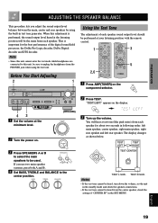
... sound output level heard at the minimum level. (HTR-5450) VOLUME 2 Turn the power on. INTRODUCTION PREPARATION BASIC OPERATION ADVANCED OPERATION ADJUSTING THE SPEAKER BALANCE This procedure lets you use two main speaker systems, press both A and B. When this unit, be sure to be performed at your listening position with the remote control. 1 3 5 2,6 1 Press AMP(TUNER) on the display. 3 Turn up the volume. BASS TREBLE BALANCE -+ -+ L R Using the Test Tone The adjustment of the digital sound field processor, the Dolby Pro Logic decoder, Dolby Digital decoder...
... sound output level heard at the minimum level. (HTR-5450) VOLUME 2 Turn the power on. INTRODUCTION PREPARATION BASIC OPERATION ADVANCED OPERATION ADJUSTING THE SPEAKER BALANCE This procedure lets you use two main speaker systems, press both A and B. When this unit, be sure to be performed at your listening position with the remote control. 1 3 5 2,6 1 Press AMP(TUNER) on the display. 3 Turn up the volume. BASS TREBLE BALANCE -+ -+ L R Using the Test Tone The adjustment of the digital sound field processor, the Dolby Pro Logic decoder, Dolby Digital decoder...
Owner's Manual
Page 26
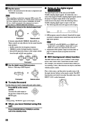
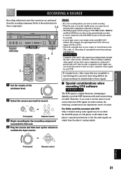
... control. PCM K HZ 2. VOLUME or Front panel Remote control If desired, adjust BASS, TREBLE, BALANCE, etc. Refer to temporarily mute audio output. Refer to "PRESET REMOTE CONTROL". 6 Adjust the volume to the previous volume level, press MUTE again. Refer to BOTH, the sound is set to "Selecting a DSP Program". Note • When controlling an audio/video component (MD recorder, CD player, DVD player, tape deck, etc.) with a sound from only the left main speakers. These controls are watching a video.) This function can also handle 96-kHz sampling digital signals...
... control. PCM K HZ 2. VOLUME or Front panel Remote control If desired, adjust BASS, TREBLE, BALANCE, etc. Refer to temporarily mute audio output. Refer to "PRESET REMOTE CONTROL". 6 Adjust the volume to the previous volume level, press MUTE again. Refer to BOTH, the sound is set to "Selecting a DSP Program". Note • When controlling an audio/video component (MD recorder, CD player, DVD player, tape deck, etc.) with a sound from only the left main speakers. These controls are watching a video.) This function can also handle 96-kHz sampling digital signals...
Owner's Manual
Page 28
... SET MENU is set to NON, the center channel sound is output from the main speakers and the rear speakers. DSP program name I On the front panel STANDBY /ON D I G I TA L SURROUND BASS TREBLE BALANCE -+ -+ L R SPEAKERS A B ON OFF D I G I On the remote control 1 2 1 Press AMP(TUNER) on (see page 25). Refer to select the desired program. I TA L VOLUME PROGRAM EFFECT PRESET/TUNING PHONES S VIDEO VIDEO L AUDIO R OPTICAL A/B/C/D/E PRESET /TUNING FM/AM EDIT MEMORY TUNING MODE MAN'L/AUTO FM AUTO/MAN'L MONO INPUT MODE INPUT 6CH INPUT (HTR-5450) SILENT VIDEO...
... SET MENU is set to NON, the center channel sound is output from the main speakers and the rear speakers. DSP program name I On the front panel STANDBY /ON D I G I TA L SURROUND BASS TREBLE BALANCE -+ -+ L R SPEAKERS A B ON OFF D I G I On the remote control 1 2 1 Press AMP(TUNER) on (see page 25). Refer to select the desired program. I TA L VOLUME PROGRAM EFFECT PRESET/TUNING PHONES S VIDEO VIDEO L AUDIO R OPTICAL A/B/C/D/E PRESET /TUNING FM/AM EDIT MEMORY TUNING MODE MAN'L/AUTO FM AUTO/MAN'L MONO INPUT MODE INPUT 6CH INPUT (HTR-5450) SILENT VIDEO...
Owner's Manual
Page 35
... DSP program and the setting of VOLUME, BASS, TREBLE and BALANCE have DTS signals recorded on them, the following considerations and adjustments need to be recorded. • A given input source is not output on the same REC OUT channel. (For example, the signal input from VCR 1 IN is set in the standby mode, you want to the instructions for these components. 1,4 STANDBY /ON D I G I TA L SURROUND BASS TREBLE BALANCE -+ -+ L R SPEAKERS A B ON OFF (HTR-5450) D I G I Special considerations when recording DTS software HTR-5450 only...
... DSP program and the setting of VOLUME, BASS, TREBLE and BALANCE have DTS signals recorded on them, the following considerations and adjustments need to be recorded. • A given input source is not output on the same REC OUT channel. (For example, the signal input from VCR 1 IN is set in the standby mode, you want to the instructions for these components. 1,4 STANDBY /ON D I G I TA L SURROUND BASS TREBLE BALANCE -+ -+ L R SPEAKERS A B ON OFF (HTR-5450) D I G I Special considerations when recording DTS software HTR-5450 only...
Owner's Manual
Page 37
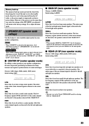
... LVL"). • HTR-5450 only When 96-kHz sampling digital signals are input to this if you have a large center speaker. SMALL Select this if you have large left and right main speakers. I CENTER SP (center speaker mode) By adding a center speaker to the center speaker. The low-frequency signals (90 Hz and below ) of the center channel are directed to the main speakers even if you adjusted will return to the speakers selected with "BASS OUT". Notes...
... LVL"). • HTR-5450 only When 96-kHz sampling digital signals are input to this if you have a large center speaker. SMALL Select this if you have large left and right main speakers. I CENTER SP (center speaker mode) By adding a center speaker to the center speaker. The low-frequency signals (90 Hz and below ) of the center channel are directed to the main speakers even if you adjusted will return to the speakers selected with "BASS OUT". Notes...
Owner's Manual
Page 39
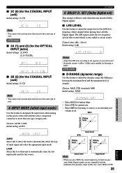
... minimum level of sounds). LAST Select this to set ) This setting is only added to allow this case, select MAX or STD. 35 English APPENDIX BASIC OPERATION ADVANCED OPERATION PREPARATION INTRODUCTION I D-RANGE (dynamic range) Use this feature to designate the input mode when turning on the power of the LFE (lowfrequency effect) channel when playing back a Dolby Digital signal. HTR-5440 I 3A (1) and (2) (for the OPTICAL INPUT jacks) Initial settings: (1) DVD (2) D-TV/CBL I 3C (5) (for the COAXIAL INPUT jack) Initial setting...
... minimum level of sounds). LAST Select this to set ) This setting is only added to allow this case, select MAX or STD. 35 English APPENDIX BASIC OPERATION ADVANCED OPERATION PREPARATION INTRODUCTION I D-RANGE (dynamic range) Use this feature to designate the input mode when turning on the power of the LFE (lowfrequency effect) channel when playing back a Dolby Digital signal. HTR-5440 I 3A (1) and (2) (for the OPTICAL INPUT jacks) Initial settings: (1) DVD (2) D-TV/CBL I 3C (5) (for the COAXIAL INPUT jack) Initial setting...
Owner's Manual
Page 40
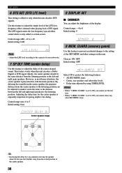
... the SET MENU and other SET MENU items. ms Center speaker image C L C R RL RR y • Increasing the delay by using TIME/LEVEL Notes • When "9 MEM. The LFE signal carries the low-frequency special effect sound which is placed in most home situations, the center speaker is only added to certain scenes. Choices: ON, OFF Initial setting: OFF Select ON to protect the following features: • All SET MENU items • Center, rear speakers and subwoofer levels • Delay time adjusted...
... the SET MENU and other SET MENU items. ms Center speaker image C L C R RL RR y • Increasing the delay by using TIME/LEVEL Notes • When "9 MEM. The LFE signal carries the low-frequency special effect sound which is placed in most home situations, the center speaker is only added to certain scenes. Choices: ON, OFF Initial setting: OFF Select ON to protect the following features: • All SET MENU items • Center, rear speakers and subwoofer levels • Delay time adjusted...
Owner's Manual
Page 44
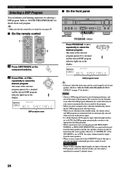
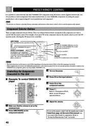
... eight component selector buttons. Refer to "Setting the Manufacturer Code" for a YAMAHA DVD player is factory set . Component Selector Buttons There are set for the YAMAHA CD recorder and tape deck can also be controlled. AMP(TUNER) You can be controlled in the DVD/LD and DVD MENU modes. If unable to operate your YAMAHA A/V component, please try using the remote control supplied with this unit. Controlling the Components Connected to This Unit I Example: To control YAMAHA CD player 5 7 2 3 4 6 3 Turn on the power. 4 Press CD on the input...
... eight component selector buttons. Refer to "Setting the Manufacturer Code" for a YAMAHA DVD player is factory set . Component Selector Buttons There are set for the YAMAHA CD recorder and tape deck can also be controlled. AMP(TUNER) You can be controlled in the DVD/LD and DVD MENU modes. If unable to operate your YAMAHA A/V component, please try using the remote control supplied with this unit. Controlling the Components Connected to This Unit I Example: To control YAMAHA CD player 5 7 2 3 4 6 3 Turn on the power. 4 Press CD on the input...
Owner's Manual
Page 49
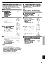
... original remote control supplied with your component. 4 Use the numeric buttons to be controlled. 3 Press both VOLUME buttons (u/d) at the same time for about four seconds. If your component cannot be used . The code set in the DVD/LD mode is also simultaneously set in the CBL/SAT and DVD MENU modes if a cable TV or satellite tuner, or DVD player is necessary to first set up the code for an LD player in the DVD/LD mode. 1 Turn...
... original remote control supplied with your component. 4 Use the numeric buttons to be controlled. 3 Press both VOLUME buttons (u/d) at the same time for about four seconds. If your component cannot be used . The code set in the DVD/LD mode is also simultaneously set in the CBL/SAT and DVD MENU modes if a cable TV or satellite tuner, or DVD player is necessary to first set up the code for an LD player in the DVD/LD mode. 1 Turn...
Owner's Manual
Page 50
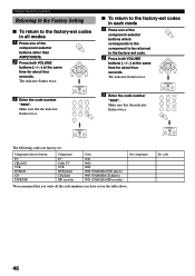
... the code number "0000". Component selector button TV CBL/SAT VCR DVD/LD CD TAPE/MD Component TV Cable TV VCR DVD player CD player MD recorder Code 0101 0006 0002 0008 (YAMAHA DVD player) 0005 (YAMAHA CD player) 0024 (YAMAHA MD recorder) Set component We recommend that you write all modes 1 Press one of the component selector buttons other than AMP(TUNER). 2 Press both VOLUME buttons (u/d) at the same time for about four seconds. PRESET REMOTE CONTROL Returning to the Factory Setting...
... the code number "0000". Component selector button TV CBL/SAT VCR DVD/LD CD TAPE/MD Component TV Cable TV VCR DVD player CD player MD recorder Code 0101 0006 0002 0008 (YAMAHA DVD player) 0005 (YAMAHA CD player) 0024 (YAMAHA MD recorder) Set component We recommend that you write all modes 1 Press one of the component selector buttons other than AMP(TUNER). 2 Press both VOLUME buttons (u/d) at the same time for about four seconds. PRESET REMOTE CONTROL Returning to the Factory Setting...
Owner's Manual
Page 54
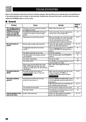
... connected or the plug is muted. The sleep timer has functioned. Remedy Firmly connect the power cord. Connect the cables properly. If the problem you are not secure. Incorrect input or output cable connections. The sound is turned down. The output and input for both the input and output. Select an appropriate input source with SPEAKERS A and/or B. Secure the connections. Press MUTE or any operation buttons to cancel a mute and adjust the volume. HTR-5450 only Check the IMPEDANCE SELECTOR switch...
... connected or the plug is muted. The sleep timer has functioned. Remedy Firmly connect the power cord. Connect the cables properly. If the problem you are not secure. Incorrect input or output cable connections. The sound is turned down. The output and input for both the input and output. Select an appropriate input source with SPEAKERS A and/or B. Secure the connections. Press MUTE or any operation buttons to cancel a mute and adjust the volume. HTR-5450 only Check the IMPEDANCE SELECTOR switch...
Owner's Manual
Page 62
... BGV function 22 C CBL/SAT mode 44 CD mode 42 CINEMA DSP 47, 56 Connections Antennas 26 Audio components (MD recorder, CD recorder and CD player 12 External decoder 12 Power supply cords 18 Speakers 16 Video components (DVD player, VCR and TV/digital TV or cable TV/satellite tuner 14 D Delay time 37 Display 8 DISPLAY SET (SET MENU 36 DOLBY D. SET (SET MENU) D-RANGE 35 LFE LEVEL 35 Dolby Digital 56 Dolby Surround (Dolby Pro Logic 56 DSP program CINEMA DSP program 47 Hi-Fi DSP program 47 DTS 56 DTS SET (SET MENU 36 Dust protection cap 12 DVD/LD mode 43 DVD MENU mode 43...
... BGV function 22 C CBL/SAT mode 44 CD mode 42 CINEMA DSP 47, 56 Connections Antennas 26 Audio components (MD recorder, CD recorder and CD player 12 External decoder 12 Power supply cords 18 Speakers 16 Video components (DVD player, VCR and TV/digital TV or cable TV/satellite tuner 14 D Delay time 37 Display 8 DISPLAY SET (SET MENU 36 DOLBY D. SET (SET MENU) D-RANGE 35 LFE LEVEL 35 Dolby Digital 56 Dolby Surround (Dolby Pro Logic 56 DSP program CINEMA DSP program 47 Hi-Fi DSP program 47 DTS 56 DTS SET (SET MENU 36 Dust protection cap 12 DVD/LD mode 43 DVD MENU mode 43...


