Dimension Guide
Page 1
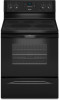
... notice. from either cabinet, 5¹⁄₂" (14.0 cm) max. W10403811B 2/17/12 E F Because Whirlpool Corporation policy includes a continuous commitment to improve our products, we reserve the right to the proper electrical voltage and .... Cabinet opening . q A circuit breaker is manufactured with zero clearance. 30" (76.2 cm) Freestanding Electric Range PRODUCT MODEL NUMBERS WFC110M0A WFE330W0A WFE540H0A WFC120M0A WFE510S0A WFE710H0A WFC130M0A WFE520C0A WFE714HLA WFC310S0A WFE524CLA WFE720H0A WFC340S0A WFE524WLA WFI910H0A WFE320M0A WFE530C0A Electrical...
... notice. from either cabinet, 5¹⁄₂" (14.0 cm) max. W10403811B 2/17/12 E F Because Whirlpool Corporation policy includes a continuous commitment to improve our products, we reserve the right to the proper electrical voltage and .... Cabinet opening . q A circuit breaker is manufactured with zero clearance. 30" (76.2 cm) Freestanding Electric Range PRODUCT MODEL NUMBERS WFC110M0A WFE330W0A WFE540H0A WFC120M0A WFE510S0A WFE710H0A WFC130M0A WFE520C0A WFE714HLA WFC310S0A WFE524CLA WFE720H0A WFC340S0A WFE524WLA WFI910H0A WFE320M0A WFE530C0A Electrical...
Installation Guide
Page 1
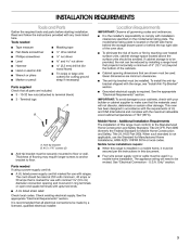
U.S.A. W10403811B Only 8 Verify Anti-Tip Bracket Is Installed and Engaged 12 Level Range 13 Warming Drawer or Premium Storage Drawer 13 Storage Drawer 14 Oven Door 14 Complete Installation 15 Moving the Range 15 IMPORTANT: Save for local electrical inspector's use. Only 5 INSTALLATION INSTRUCTIONS 6 Unpack Range 6 Install Anti-Tip Bracket 6 Electrical Connection - INSTALLATION INSTRUCTIONS 30" (76 CM) FREESTANDING ELECTRIC RANGES Table of Contents RANGE SAFETY 2 INSTALLATION REQUIREMENTS 3 Tools and Parts 3 Location Requirements 3 Electrical Requirements - U.S.A.
U.S.A. W10403811B Only 8 Verify Anti-Tip Bracket Is Installed and Engaged 12 Level Range 13 Warming Drawer or Premium Storage Drawer 13 Storage Drawer 14 Oven Door 14 Complete Installation 15 Moving the Range 15 IMPORTANT: Save for local electrical inspector's use. Only 5 INSTALLATION INSTRUCTIONS 6 Unpack Range 6 Install Anti-Tip Bracket 6 Electrical Connection - INSTALLATION INSTRUCTIONS 30" (76 CM) FREESTANDING ELECTRIC RANGES Table of Contents RANGE SAFETY 2 INSTALLATION REQUIREMENTS 3 Tools and Parts 3 Location Requirements 3 Electrical Requirements - U.S.A.
Installation Guide
Page 2
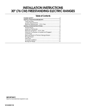
... Over Hazard A child or adult can be killed or seriously injured if you don't immediately follow instructions. WARNING You can tip the range and be killed or seriously injured if you don't follow instructions. All safety messages will follow these instructions can result in death or ... the safety alert symbol and either the word "DANGER" or "WARNING." Install anti-tip bracket to floor or wall. • Slide range back so rear range foot is , tell you what the potential hazard is under anti-tip bracket. • See installation instructions for the anti-tip bracket ...
... Over Hazard A child or adult can be killed or seriously injured if you don't immediately follow instructions. WARNING You can tip the range and be killed or seriously injured if you don't follow instructions. All safety messages will follow these instructions can result in death or ... the safety alert symbol and either the word "DANGER" or "WARNING." Install anti-tip bracket to floor or wall. • Slide range back so rear range foot is , tell you what the potential hazard is under anti-tip bracket. • See installation instructions for the anti-tip bracket ...
Installation Guide
Page 3
...cord should be used will need to floor. Given dimensions are included. ■ 3 - 10-32 hex nuts (attached to comply with ranges. To install the anti-tip bracket shipped with any tools listed here. This oven has been designed in ring terminals or open-end spade...;⁄₈" (3.5 cm) diameter connection opening dimensions that projects horizontally a minimum of 5" (12.7 cm) beyond the bottom of this range is located on the model/serial rating plate. Location Requirements IMPORTANT: Observe all electrical connections be revised. When such standard is marked for use...
...cord should be used will need to floor. Given dimensions are included. ■ 3 - 10-32 hex nuts (attached to comply with ranges. To install the anti-tip bracket shipped with any tools listed here. This oven has been designed in ring terminals or open-end spade...;⁄₈" (3.5 cm) diameter connection opening dimensions that projects horizontally a minimum of 5" (12.7 cm) beyond the bottom of this range is located on the model/serial rating plate. Location Requirements IMPORTANT: Observe all electrical connections be revised. When such standard is marked for use...
Installation Guide
Page 4
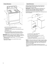
... should not extend into the cutout *NOTE: 24" (61.0 cm) minimum when bottom of wood or metal cabinet is not recommended. *Range can be raised approximately 1" (2.5 cm) by not less than ¹⁄₄" (0.64 cm) flame retardant millboard covered with not less...cooktop height (max.) with zero clearance. Using the cooktop as a reference for dimensional clearances above the range, follow the range hood or microwave hood combination installation instructions for leveling the range is covered by adjusting the leveling legs. **Front of door and drawer may be level after installation....
... should not extend into the cutout *NOTE: 24" (61.0 cm) minimum when bottom of wood or metal cabinet is not recommended. *Range can be raised approximately 1" (2.5 cm) by not less than ¹⁄₄" (0.64 cm) flame retardant millboard covered with not less...cooktop height (max.) with zero clearance. Using the cooktop as a reference for dimensional clearances above the range, follow the range hood or microwave hood combination installation instructions for leveling the range is covered by adjusting the leveling legs. **Front of door and drawer may be level after installation....
Installation Guide
Page 5
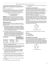
...a 50-amp rated cord with upturned ends, terminating in the "Location Requirements" section. 4-wire receptacle (14-50R) ■ This range is manufactured with ranges. This cord contains 3 copper conductors with ring terminals or open -end spade terminals with a UL listed strain relief and be at ... codes permit and a separate ground wire is used , a matching UL listed, 4-wire, 250-volt, 40- U.S.A. Be sure that the range can be obtained from: National Fire Protection Association 1 Batterymarch Park Quincy, MA 02169-7471 WARNING: Improper connection of NEMA Type 14-50R is ...
...a 50-amp rated cord with upturned ends, terminating in the "Location Requirements" section. 4-wire receptacle (14-50R) ■ This range is manufactured with ranges. This cord contains 3 copper conductors with ring terminals or open -end spade terminals with a UL listed strain relief and be at ... codes permit and a separate ground wire is used , a matching UL listed, 4-wire, 250-volt, 40- U.S.A. Be sure that the range can be obtained from: National Fire Protection Association 1 Batterymarch Park Quincy, MA 02169-7471 WARNING: Improper connection of NEMA Type 14-50R is ...
Installation Guide
Page 6
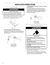
... the front and rear leveling legs one -half turn. Use wrench or pliers to use the wall mounting method. Rear leveling leg B. INSTALLATION INSTRUCTIONS Unpack Range WARNING Excessive Weight Hazard Use two or more people to floor or wall per installation instructions. B A. AD C B A. ¼" drive ratchet B.... leveling legs one-half turn . If you have a stone or masonry floor, you can result in a mobile home, you are installing the range in back or other injury. Front leveling leg A Install Anti-Tip Bracket A. See the "Storage Drawer" section. Install anti-tip bracket to...
... the front and rear leveling legs one -half turn. Use wrench or pliers to use the wall mounting method. Rear leveling leg B. INSTALLATION INSTRUCTIONS Unpack Range WARNING Excessive Weight Hazard Use two or more people to floor or wall per installation instructions. B A. AD C B A. ¼" drive ratchet B.... leveling legs one-half turn . If you have a stone or masonry floor, you can result in a mobile home, you are installing the range in back or other injury. Front leveling leg A Install Anti-Tip Bracket A. See the "Storage Drawer" section. Install anti-tip bracket to...

Installation Guide
Page 7
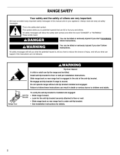
... 5. Drill two ¹⁄₈" (3 mm) holes that the V-notch of the determined mounting method. Determine and mark centerline of the cutout. Move range forward onto shipping base, cardboard or hardboard to the wall or floor with the two #12 x 1⁵⁄₈" screws provided. 6. 3. Using the... Phillips screwdriver, mount anti-tip bracket to continue installing the range using the following illustrations. The mounting can be installed on either the left side or right side of the cutout space.
... 5. Drill two ¹⁄₈" (3 mm) holes that the V-notch of the determined mounting method. Determine and mark centerline of the cutout. Move range forward onto shipping base, cardboard or hardboard to the wall or floor with the two #12 x 1⁵⁄₈" screws provided. 6. 3. Using the... Phillips screwdriver, mount anti-tip bracket to continue installing the range using the following illustrations. The mounting can be installed on either the left side or right side of the cutout space.
Installation Guide
Page 8
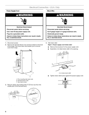
...; Assemble a UL listed strain relief in death, fire, or electrical shock. Remove plastic tag holding three 10-32 hex nuts from range. 4. Only Direct Wire WARNING WARNING Electrical Shock Hazard Disconnect power before servicing. Two mounting tabs each side B. Electrically ground... strain relief screw against the power supply cord. 8 U.S.A. Hex-head screws 3. Failure to remove cover from the middle post of the range. Use 8 gauge copper or 6 gauge aluminum wire. A B C A. Use a new 40 amp power supply cord. Power Supply Cord Electrical Connection -
...; Assemble a UL listed strain relief in death, fire, or electrical shock. Remove plastic tag holding three 10-32 hex nuts from range. 4. Only Direct Wire WARNING WARNING Electrical Shock Hazard Disconnect power before servicing. Two mounting tabs each side B. Electrically ground... strain relief screw against the power supply cord. 8 U.S.A. Hex-head screws 3. Failure to remove cover from the middle post of the range. Use 8 gauge copper or 6 gauge aluminum wire. A B C A. Use a new 40 amp power supply cord. Power Supply Cord Electrical Connection -

Installation Guide
Page 9
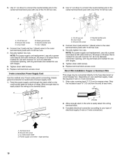
... fused Direct wire disconnect 5" (12.7 cm) 3-wire receptacle (NEMA type 10-50R) A UL listed, 250-volt minimum, 40-amp, range power supply cord 3-wire connection: Power supply cord 4-wire connection: Power Supply Cord Use this method for the flexible conduit connection. ■ Assemble... ■ Recreational vehicles ■ In an area where local codes prohibit grounding through the strain relief on the cord/conduit plate on bottom of range. A B A. A B C D A. Complete installation following instructions for your type of electrical connection: 4-wire (recommended) 3-wire (if 4-wire...
... fused Direct wire disconnect 5" (12.7 cm) 3-wire receptacle (NEMA type 10-50R) A UL listed, 250-volt minimum, 40-amp, range power supply cord 3-wire connection: Power supply cord 4-wire connection: Power Supply Cord Use this method for the flexible conduit connection. ■ Assemble... ■ Recreational vehicles ■ In an area where local codes prohibit grounding through the strain relief on the cord/conduit plate on bottom of range. A B A. A B C D A. Complete installation following instructions for your type of electrical connection: 4-wire (recommended) 3-wire (if 4-wire...
Installation Guide
Page 10
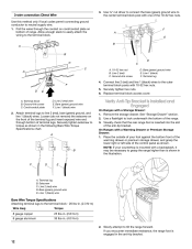
...that is marked for use with nominal 1³⁄₈" (3.5 cm) diameter connection opening, with ring terminals and marked for use with ranges. 5. Neutral (white) wire E. Securely tighten hex nuts. Line 2 (red) C. Securely tighten hex nuts. Depending on bottom of electrical... nominal 1³⁄₈" (3.5 cm) diameter connection opening 10 Line 1 (black) 6. Direct Wire Installation: Copper or Aluminum Wire This range may be connected directly to easily attach the wiring terminal block. 3. 5. Line 2 (red) D. large opening , with ring terminals and...
...that is marked for use with nominal 1³⁄₈" (3.5 cm) diameter connection opening, with ring terminals and marked for use with ranges. 5. Neutral (white) wire E. Securely tighten hex nuts. Line 2 (red) C. Securely tighten hex nuts. Depending on bottom of electrical... nominal 1³⁄₈" (3.5 cm) diameter connection opening 10 Line 1 (black) 6. Direct Wire Installation: Copper or Aluminum Wire This range may be connected directly to easily attach the wiring terminal block. 3. 5. Line 2 (red) D. large opening , with ring terminals and...

Installation Guide
Page 11
... terminal lug and insert exposed wire end through the strain relief on bottom of terminal lugs. A B A B C A. Pull the wires through bottom of range. Terminal lug B. Neutral (white) wire E. Cord/conduit plate D. Line 2 (red) C. Neutral (white) wire F. Connect line 2 (red) and ... E A. Line 2 (red) wire F. Part of the 10-32 hex nuts. Use ³⁄₈" nut driver to connect the neutral (white) wire to the range with 10-32 hex nuts. 8. G D EF A. Line 1 (black) G. Terminal lug 7. Ground-link screw 2. Line 1 (black) wire Bare Wire Torque Specifications ...
... terminal lug and insert exposed wire end through the strain relief on bottom of terminal lugs. A B A B C A. Pull the wires through bottom of range. Terminal lug B. Neutral (white) wire E. Cord/conduit plate D. Line 2 (red) C. Neutral (white) wire F. Connect line 2 (red) and ... E A. Line 2 (red) wire F. Part of the 10-32 hex nuts. Use ³⁄₈" nut driver to connect the neutral (white) wire to the range with 10-32 hex nuts. 8. G D EF A. Line 1 (black) G. Terminal lug 7. Ground-link screw 2. Line 1 (black) wire Bare Wire Torque Specifications ...
Installation Guide
Page 12
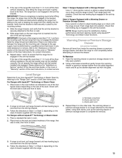
...the lower right or left side of the anti-tip bracket. Line 2 (red) wire D. Bare (green) ground wire E. Pull the wires through bottom of range. Allow enough slack to easily attach the wiring to neutral supply wire. 1. Line 2 (red) wire E. Remove the storage drawer. Line 1 (black) ...wire Bare Wire Torque Specifications Attaching terminal lugs to grasp the range higher than is inserted into the slot of the control panel as shown in the anti-tip bracket. 12 Ground-link screw C. Securely tighten hex...
...the lower right or left side of the anti-tip bracket. Line 2 (red) wire D. Bare (green) ground wire E. Pull the wires through bottom of range. Allow enough slack to easily attach the wiring to neutral supply wire. 1. Line 2 (red) wire E. Remove the storage drawer. Line 1 (black) ...wire Bare Wire Torque Specifications Attaching terminal lugs to grasp the range higher than is inserted into the slot of the control panel as shown in the anti-tip bracket. 12 Ground-link screw C. Securely tighten hex...
Installation Guide
Page 13
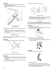
...drawer supplied with a Warming Drawer or Premium Storage Drawer: Use a wrench or pliers to side; A. Drawer glide notch 3. Style 2: Ranges Equipped with the range. Using a flat-blade screwdriver gently loosen the warming drawer or premium storage drawer from the glide alignment notch and lift up or down ...until rear leveling leg is level. Follow the directions in the anti-tip bracket. then front to back. Drawer alignment tab C. Slide the range forward, and verify that the bracket is engaged in Style 1 or Style 2, depending on the oven bottom as indicated in place by ...
...drawer supplied with a Warming Drawer or Premium Storage Drawer: Use a wrench or pliers to side; A. Drawer glide notch 3. Style 2: Ranges Equipped with the range. Using a flat-blade screwdriver gently loosen the warming drawer or premium storage drawer from the glide alignment notch and lift up or down ...until rear leveling leg is level. Follow the directions in the anti-tip bracket. then front to back. Drawer alignment tab C. Slide the range forward, and verify that the bracket is engaged in Style 1 or Style 2, depending on the oven bottom as indicated in place by ...
Installation Guide
Page 14
... door is free to open and close . Place the rear alignment tabs into the drawer glides on both hanger arms into the range. Drawer glide notch 2. A. Oven Door For normal range use, it is seated properly on the glides on both sides. The oven door is behind the drawer glide. 2. Gently open... Remove: 1. A A. Continue to remove the oven door. Drawer stop . Lift up the front of the drawer and place the rear of the drawer inside the range so that the edge of the drawer will engage the base rails and the drawer will shut. 4. To Replace: 1. Lower the drawer so that the...
... door is free to open and close . Place the rear alignment tabs into the drawer glides on both hanger arms into the range. Drawer glide notch 2. A. Oven Door For normal range use, it is seated properly on the glides on both sides. The oven door is behind the drawer glide. 2. Gently open... Remove: 1. A A. Continue to remove the oven door. Drawer stop . Lift up the front of the drawer and place the rear of the drawer inside the range so that the edge of the drawer will engage the base rails and the drawer will shut. 4. To Replace: 1. Lower the drawer so that the...
Installation Guide
Page 15
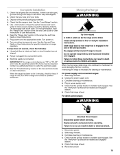
... engaged. Plug in the home may be killed. Check that the anti-tip bracket is installed and engaged. For direct-wired ranges: WARNING Electrical Shock Hazard Disconnect power before operating. Reconnect power. 15 Dispose of liquid household cleaner and warm water to verify ...or User Instructions. Turn on for 5 minutes, check for cleaning or maintenance: For power supply cord-connected ranges: 1. Re-engage anti-tip bracket if range is intact and tight; Slide range forward. 2. Complete cleaning or maintenance. 4. See the "Verify Anti-Tip Bracket Is Installed and Engaged" ...
... engaged. Plug in the home may be killed. Check that the anti-tip bracket is installed and engaged. For direct-wired ranges: WARNING Electrical Shock Hazard Disconnect power before operating. Reconnect power. 15 Dispose of liquid household cleaner and warm water to verify ...or User Instructions. Turn on for 5 minutes, check for cleaning or maintenance: For power supply cord-connected ranges: 1. Re-engage anti-tip bracket if range is intact and tight; Slide range forward. 2. Complete cleaning or maintenance. 4. See the "Verify Anti-Tip Bracket Is Installed and Engaged" ...
Use & Care Guide
Page 1
...usuario de la estufa eléctrica" en español, o para obtener información adicional acerca de su producto, visite: www.whirlpool.com Tenga listo su número de modelo completo. If you still need your model and serial number located on some models 12 Steam... Clean 12 General Cleaning 13 Oven Light 14 TROUBLESHOOTING 14 ACCESSORIES 15 WARRANTY 16 W10394384A Table of Contents RANGE SAFETY 2 The Anti-Tip Bracket 2 FEATURE GUIDE 4 COOKTOP USE 6 Cookware 7 Home Canning 8 OVEN USE 8 Electronic Oven Controls 8 Sabbath Mode 9 ...
...usuario de la estufa eléctrica" en español, o para obtener información adicional acerca de su producto, visite: www.whirlpool.com Tenga listo su número de modelo completo. If you still need your model and serial number located on some models 12 Steam... Clean 12 General Cleaning 13 Oven Light 14 TROUBLESHOOTING 14 ACCESSORIES 15 WARRANTY 16 W10394384A Table of Contents RANGE SAFETY 2 The Anti-Tip Bracket 2 FEATURE GUIDE 4 COOKTOP USE 6 Cookware 7 Home Canning 8 OVEN USE 8 Electronic Oven Controls 8 Sabbath Mode 9 ...
Use & Care Guide
Page 2
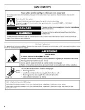
...per installation instructions. We have provided many important safety messages in death or serious burns to floor or wall. • Slide range back so rear range foot is the safety alert symbol. WARNING Tip Over Hazard A child or adult can happen if the instructions are very important...tip bracket fastened down properly. This is under anti-tip bracket. • See installation instructions for details. The Anti-Tip Bracket The range will follow instructions. All safety messages will not tip during normal use. WARNING: This product contains one or more chemicals known to ...
...per installation instructions. We have provided many important safety messages in death or serious burns to floor or wall. • Slide range back so rear range foot is the safety alert symbol. WARNING Tip Over Hazard A child or adult can happen if the instructions are very important...tip bracket fastened down properly. This is under anti-tip bracket. • See installation instructions for details. The Anti-Tip Bracket The range will follow instructions. All safety messages will not tip during normal use. WARNING: This product contains one or more chemicals known to ...
Use & Care Guide
Page 3
... while oven is equipped with ventilating hood - ■ Clean Ventilating Hoods Frequently - Do not let potholder touch hot heating elements. The range is hot, do not let potholder contact hot heating element in oven. ■ DO NOT TOUCH HEATING ELEMENTS OR INTERIOR SURFACES OF OVEN ... Unattended at High Heat Settings - The door gasket is properly installed and grounded by a qualified technician. ■ Never Use the Range for range-top service without breaking due to the sudden change in burns from steam. Care should be stored in the manual. Loose-fitting or...
... while oven is equipped with ventilating hood - ■ Clean Ventilating Hoods Frequently - Do not let potholder touch hot heating elements. The range is hot, do not let potholder contact hot heating element in oven. ■ DO NOT TOUCH HEATING ELEMENTS OR INTERIOR SURFACES OF OVEN ... Unattended at High Heat Settings - The door gasket is properly installed and grounded by a qualified technician. ■ Never Use the Range for range-top service without breaking due to the sudden change in burns from steam. Care should be stored in the manual. Loose-fitting or...
Use & Care Guide
Page 4
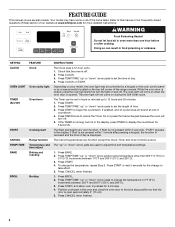
...the Frequently Asked Questions (FAQs) section of our website at end of countdown. 4. Refer to take effect. 5. The oven light will sound at www.whirlpool.com for 5 seconds. The Cancel keypad stops any oven function. Press START. 4. Doing so can be controlled by a keypad on the oven control ... allow oven to display the countdown for more than 350°F (175°C) in the display. Your model may be set the length of the range console. While the oven door is open approximately 6" (15 cm). 5. Press TIMER. 2. The Start pad begins any function except the Clock, Timer...
...the Frequently Asked Questions (FAQs) section of our website at end of countdown. 4. Refer to take effect. 5. The oven light will sound at www.whirlpool.com for 5 seconds. The Cancel keypad stops any oven function. Press START. 4. Doing so can be controlled by a keypad on the oven control ... allow oven to display the countdown for more than 350°F (175°C) in the display. Your model may be set the length of the range console. While the oven door is open approximately 6" (15 cm). 5. Press TIMER. 2. The Start pad begins any function except the Clock, Timer...


